1
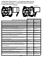
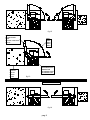
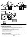
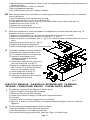
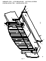
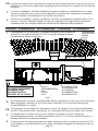
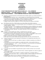
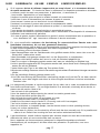
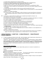
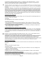
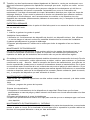
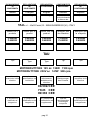
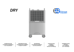
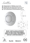
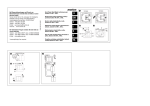
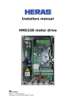
AUTOMAZIONE PER CANCELLO A BATTENTE
AUTOMATISIERUNG VON GITTERTOREN
AUTOMATIONS FOR GATES
AUTOMATISATIONS POUR PORTAIL A BATTANT
AUTOMATIZACION PARA VERJAS CON PUERTAS BATENTES
R40 12V d.c.
R30 230V a.c.
MANUALE DI USO E MANUTENZIONE
BEDIENUNGS UND WARTUNGSANLEITUNG
OPERATING AND MAINTENANCE MANUAL
MODE D’EMPLOI ET D’ ENTRETIEN
MANUAL DE USO Y MANTENIMIENTO
I
La Casa costruttrice si riserva il diritto di apportare modifiche o miglioramenti al prodotto senza alcun
preavviso. Eventuali imprecisioni o errori riscontrabili nella presente edizione, saranno corretti nella
prossima edizione. All’apertura dell’imballo verificare che il prodotto sia integro. Riciclare i materiali
secondo la normativa vigente.
D
Die Herstellerfirma behält sich das Recht vor, Änderungen o der Verbesserungen des Produktes
ohne irgendeine Vorankündigung vorzunehmen. Eventuelle in diesem Handbuch feststellbar
Ungenauigkeiten oder Fehler werden in der ächsten Ausgabe berichtigt werden. Überprüfen Sie
beim Öffnen der Verpackung, ob das Produkt unversehrt ist. Recyclen Sie das Material gemäß der
gültigen Vorschriften.
GB
The manufacturer reserves the right to modify or improve them without prior notice. Any
inaccuracies or errors found in this manual will be corrected in the next edition. When opening
the packing please check that the product is in excellent condition.
Please recycle materials in
compliance with current regulations.
F
Le Constructeur se réserve le droit d’apporter des modifications ou des améliorations au produit sans
aucun préavis. Les éventuelles imprécisions ou erreurs trouvées dans cette édition seront corrigées
dans la prochaine édition. A l’ouverture de l’emballage, vérifier que le produit est intact.
Recycler
les matériaux selon la réglementation en vigueur.
E
Este manual no dispone de la garantía que la empresa fabricante otorga a sus productos. La
empresa fabricante se reserva el derecho a aportar modificaciones o mejoras en el producto sin aviso
previo. Posibles errores o imprecisiones que se detecten en este manual se corregirán en el próximo.
Cuando abra el embalaje, compruebe la integridad del producto. Reciclar los materiales según las
normativas vigentes.
INSTALLAZIONE - MONTAGE - INSTALLATION - INSTALLATION - INSTALACION
I
La posa del prodotto dovrà essere effettuata da personale qualificato. La Ditta Costruttrice Tau declina
ogni responsabilità per danni derivanti a cose e/o persone dovuti ad una eventuale errata installazione
dell’impianto o la non messa a Norma dello stesso secondo le vigenti Leggi (vedi Direttiva Macchine).
D
Diese Arbeiten sind von Fachpersonal auszuführen. Die Herstellerfirma lehnt jede Haftung für
Personen- und/oder Sachschäden aufgrund einer falschen Installation der Anlage oder der nicht
normgerechten Gestaltung der Anlage gemäß der gültigen Vorschriften ab.
GB
Such operations must be carried out by qualified personnel.
The Manufacturer Tau declines all
responsibility for damages caused to property and/or harm to people due to an erroneous installation of
the system and its non compliance with current Guidelines.
F
Ces opérations doivent être effectuées par du personnel qualifié.
La société constructrice Tau décline
toute responsabilité pour les dommages aux choses et/ou aux personnes dus à une éventuelle
installation incorrecte ou au non respect des normes en vigueur pour ce type de dispositif.
E
Dichas operaciones deben ser realizadas por personal cualificado. El fabricante, Tau, declina toda
responsabilidad por daños a cosas, o lesiones a personas causados por un montaje incorrecto de la
instalación, o por la inobservancia de las Directivas vigentes durante la puesta a punto.
INDICE
VERZEICHNIS
CONTENTS
INDEX
INDICE
Pag.3 DIMENSIONI - MABEN - DIMENSIONS - DIMENSIONS - MEDIDAS.
Pag.4 CARATTERISTICHE TECNICHE - TECHNISCHE EIGENSCHAFTEN - TECHNICAL FEATURES
CARACTERISTIQUES TECHNIQUES - CARACTERISTICAS TECNICAS.
Pag.5 DESCRIZIONE TECNICA - TECHNICAL DESCRIPTION - DESCRIPTION TECHNIQUE
TECHNISCHE BESCHREBUNG - DESCRIPCION TECNICA.
Pag.6 MISURE DI INGOMBRO - ABMESSUNGEN UBER ALLES - OVERALL DIMENSIONS MESURES D’ENCOMBREMENT - MEDIDAS
pag.2
Pag.6 DESCRIZIONE DI MONTAGGIO - MONTAGE BESCHREIBUNG - ASSEMBLY INSTRUCTIONS DESCRIPTION DE MONTAGE - DESCRIPCION DL MONTAJE.
Pag.8 SCHEMA DI MONTAGGIO - MONTAGEANORDUNG - ASSEMBLY DESCRIPTION - DESCRIPTION DE
MONTAGE - ESQUEMA DE MONTAJE.
Pag.8 LIMITI DI IMPIEGO - VERWENDUNGSBEREICH - OPERATIONAL LIMITS - LIMITES D’EMPLOI
LIMITES DE EMPLEO.
Pag.10 ASSEMBLAGGIO COMPONENTI - ZUSAMMENBAU DER TEILE - ASSEMBLY OF COMPONENTS ASSEMBLAGE COMPOSANTS - ENSAMBLAJE COMPONENTES.
Pag.11 SBLOCCO MANUALE - MANUELLE ENTRIEGELUNG - MANUAL RELEASE - DEBLOCAGE MANUEL
DESBLOQUEO MANUAL.
Pag.12 SEZIONE DEI CAVI - KABEL SCHNITT - CABLES CROSS SECTION - SECTION DES CABLES
SECCION DE CABLES.
Pag.13 IMPIANTO TIPO - TYP DER ANLAGE - TYPICAL SYSTEM - INSTALLATION TYPE INSTALACION TIPO.
Pag.14 COLLEGAMENTI ELETTRICI - ANSCHLUB FUR MOTOREN - ELECTRICAL CONNECTIONS
BRANCHEMENT ELECTRIQUE - CONEXION ELECTRICAS.
Pag.14 AVVERTENZE - ACHTUNG - ATTENTION - ATTENTION - ATENCION.
Pag.15 VIETATO - VERBOTEN - FORBIDDEN - DEFENSE - PROHIBIDO.
Pag.16 APPENDICE - ANHAG -APPENDIX - APPENDICE - APENDICE.
I-DIMENSIONI D-MABEN GB-DIMENSIONS F-DIMENSIONS E-MEDIDAS
R30 230V a.c.
fig.1
fig.2
R40 12V d.c.
fig.3
fig.4
pag.3
I-CARATTERISTICHE TECNICHE D-TECHNISCHE EIGENSCHAFTEN
GB-TECHNICAL FEATURES F -CARACTERISTIQUES TECHNIQUES
E -CARACTERISTICAS TECNICAS
R40 12Vd.c.
R30 230V a.c.
fig.5
fig.6
TIPO, TYP, TYPE, TYPE, TIPO
R40 12Vd.c. R30 230V a.c.
Alimentazione, Stromspeisung, Power, Alimentation, Alimentacion.
12 V d.c.
230 V a.c.
Motore, Motor, Gearmotor, Moteur, Motor.
12 V d.c.
230 V a.c.
50/60 Hz.
32 Kgm.
32 Kgm.
Frequenza, Frequenz, Frequency, Fréquence, Frequencia.
12,5 µf.
Condensatore, Kondensator, Capacitor, Condensateur, Condensador.
Coppia, Drehmoment, Torque, Couple, Pareja.
Velocità nominale (a vuoto), Nenngeschwindigkeit (leer), Nominal speed
1100 rpm
(no load), Vitesse moteur (à vide), Velocidad nominal (en vacio).
900 rpm
Corrente assorbita (a vuoto), Aufgenommener (leer), Absorbed current (no
load), Courant absorbée (à vide), Corriente absorbida (en vacio).
1.5 A ± 10%
0.84/1.84 A ±
10%
Potenza assorbita, Aufgenommene Nennleistung, Absorbed rated
output, Puissance absorbée, Potencia nominal absorbida.
150 W (0.2 CV)
147 W (0.2 CV)
Rapporto di riduzione, Übersetzungsverhältnis, Reduction ratio,
Rapport de réduction, Relacion de reduccion.
1 / 1222
1 / 1222
Intervento di termoprotezione, Eingreifen des Warmeschutzes,
Thermal protection trips at, Intervention protection thermique,
Activacion termoproteccion.
140° C
Ciclo di lavoro, Arbeitzyklus, Working cicle, Cycle de travail, Ciclo de trabajo. 100 %
10 %
Temperatura di esercizio, Betriebstemperatur, Operating temperatu-20°C +60°C
re, Température de fonctionnement, Temperatura de trabajo.
-10°C +60°C
Lunghezza massima anta, Maximale Flache des Schwingtors,
Maximum gate length, Longeur maximale du battant, Longitud
maxima hoja puerta
2.5 m
2.5 m
Peso max anta, Maximale Gewicht des Flugel, Max gate weight,
Poids max battant, Peso max hoja puerta.
300 Kg
300 Kg
IP Motoriduttore, Schutzart des Motor (IP), Geramotor IP, IP
Motreducteur, IP Motoreductor.
65
65
Peso motoriduttore, Gewicht, Weight, Poids, Peso.
Tempo corsa, Laufzeit, Stroke time, Temp de course, Tiempo de carrera.
11,8 Kg
17 sec (90°)
19 sec (100°)
11,8 Kg
21 sec (90°)
24 sec (100°)
pag.4
I-DESCRIZIONE TECNICA D-TECHNISCHE BESCHREBUNG GB-TECHNICAL
DESCRIPTION F-DESCRIPTION TECHNIQUE E-DESCRIPCION TECNICA
I
1-Motore: 12Vd.c. con encoder per rallenta
mento in apertura e chiusura.
2-Motore: 230V a.c. con rallentamento
meccanico.
3-Riduttore: a doppia riduzione composto da :
ruota in ghisa, ruota in bronzo, guscio in
alluminio, lubrificazione a grasso.
4-Leve di trasmissione con zincatura
tropicalizzata.
5-Cassa di fondazione: lamiera con zincatura
tropicalizzata.
D
1-Motor: 12V g.s. mit Encoder für
Verlangsamung in Öffnung und Schließung
2-Motor: 230Va.c. mit mechanischer
Verlangsamung.
3-Untersetzungsgetriebe: mit doppelter
Untersetzung bestehend aus: Rad aus
Guss, Rad aus Bronze, Gehäuse aus
Aluminium, Schmierung mit Fett.
4-Tropenfest verzinkte Antriebshebel.
5-Fundamentkasten: tropenfest verzinktes
Blech.
fig.7
GB
1-Motor: 12 Vdc with encoder for decelerating in opening and closing.
2-Motor: 230V a.c.with mechanical decelerator.
3-Reduction gear: with dual reduction consisting of : cast iron wheel, bronze wheel, aluminium casing
lubrication with grease.
4-Transmission levers with tropicalised galvanising.
5-Foundation box: sheet metal with tropicalised galvanising.
F
1-Moteur : 12V d.c. avec dispositif encodeur pour ralentissement à l’ouverture et à la fermeture.
2-Moteur: 230V a.c. avec ralentissement mechanique.
2-Réducteur : à double réduction composé de : roue en fonte, roue en bronze, coque en aluminium,
lubrification à la graisse.
3-Leviers de transmission avec galvanisation tropicalisée.
4-Caisse de fondation: tôle avec galvanisation tropicalisée.
E
1-Motor: 12V d.c. con codificador para desaceleración durante la apertura y cierre.
2-Motor: 230V a.c. con desaceleración mecánica.
3-Reductor: de reducción doble compuesto de : rueda de arrabio, rueda de bronce, carcasa de
aluminio, lubricación por grasa.
4-Palancas de transmisión con galvanizado tropicalizado.
5-Caja de cimentación: chapa galvanizada tropicalizada.
pag.5
I-MISURE DI INGOMBRO D-ABMESSUNGEN UBER ALLES GB-OVERALL
DIMENSIONS F-MESURES D’ENCOMBREMENT E-MEDIDAS
fig.8
fig.9
I-DESCRIZIONE DI MONTAGGIO D-MONTAGE BESCHREIBUNG
GB-ASSEMBLY INSTRUCTIONS F-DESCRIPTION DE MONTAGE
E-DESCRIPCION DL MONTAJE
I
D
1) Verificare l’efficienza delle parti fisse e mobili della struttura che sarà automatizzata.
2) In funzione del tipo di struttura (fig 11...16), scegliere la posizione più idonea per il motoriduttore
3) Eseguire lo scavo sulla base delle misure riportate in fig 10.
4) Collocare la cassa di fondazione all’interno dello scavo in modo che il perno saldato alla cassa
sia in asse con il cardine superiore del cancello (fig 10).
5) Inserire due tubi per il drenaggio dell’acqua utilizzando i fori praticati sulla cassa (part.4 di fig 10 e
part.11 di fig 17).
6) Inserire una guaina spiralata per il passaggio dei cavi motore usando il foro sulla cassa (part.5 di
fig 10 e part.10 di fig 17).
7) Gettare (il calcestruzzo) all’interno dello scavo; curare la messa in bolla della cassa che deve
sporgere dal livello del pavimento finito di 5 mm (=spessore del coperchio).
8) Posizionare il motoriduttore nella cassa e bloccarlo con 4 dadi.
9) Montare tutti gli organi di collegamento (fig 17).
10) Saldare l’anta al gruppo (part.7 di fig 10).
1)
2)
3)
4)
Die Effizienz der festen und beweglichen Teile der Struktur prüfen, die automatisiert werden wird.
Je nach Strukturtyp (Abb. 11...16), die für den Getriebemotor geeignetste Stellung wählen.
Die Ausgrabung auf der Basis der in Abb.10 angegebenen Maße ausführen.
Den Fundamentkasten so in der Ausgrabung anordnen, dass der an den Kasten geschweisste
Zapfen mit dem oberen Angelzapfen des Tors rechtwinklig ist (Abb. 10).
5) Zwei Rohre für die Drainage des Wassers einfügen, dazu die Löcher im Fundamentkasten benutzen
(Detail 4 in Abb.10 und Detail 11 in Abb.17).
pag.6
6) Einen spiralenförmigen Mantel für den Durchgang der Motorkabel einfügen, dazu das Loch im
Fundamentkasten benutzen (Detail 5 in Abb. 10 und Detail 10 in Abb.17).
7) Den Fundamentkasten einbetonieren; die Nivellierung des Fundamentkastens beachten, der 5 mm
(= Stärke des Deckels) über den fertigen Boden hervorragen muss.
8) Den Getriebemotor im Fundamentkasten anordnen und mit 4 Nutmuttern blockieren.
9) Alle Anschlussteile montieren (Abb. 17).
10) Den Flügel an die Gruppe schweissen (Detail 7 in Abb.10).
GB
1) Check efficiency of the fixed and mobile parts of the structure to be automated.
2) Always choose the most suitable position for the gearmotor according to the type of structure
(figs. 11...16).
3) Excavate according to the measurements given in fig. 10.
4) Place the foundation box in the hole excavated so the pin welded to the box is on the same axis as
the gate’s top hinge (fig. 10).
5) Insert the tubes for draining the water, using the holes on the box (item 4 of fig. 10 and item 11 of
fig17).
6) Insert a spiralled sheath for passing the motor’s cables, using the hole on the box (item 5 of fig.10
and item 10 of fig.17).
7) Cast (the concrete) inside the excavated hole; make sure the box is level; it must be 5 mm higher than
the finished floor (= thickness of the cover).
8) Position the gearmotor in the box and lock it with 4 nuts.
9) Assemble all the connection elements (fig. 17).
10) Weld the gate to the unit (item 7 of fig. 10).
F
1) Vérifier l’efficacité des parties fixes et mobiles de la structure qui sera automatisée.
2) En fonction du type de structure (fig. 11...16), choisir la position la plus adaptée pour le motoréducteur.
3) Creuser le trou sur la base des mesures données dans la fig. 10.
4) Placer la caisse de fondation dans le trou de manière que le pivot soudé à la caisse soit dans l’axe
du gond supérieur du portail (fig. 10).
5) Introduire deux tuyaux pour le drainage de l’eau en utilisant les trous pratiqués sur la caisse (pos. 4
fig. 10 et pos.11 fig.17).
6) Introduire une gaine spiralée pour le passage des câbles moteur en utilisant le trou présent sur la
caisse (pos. 5 - fig. 10 et pos.10 -fig.17).
7) Couler le ciment à l’intérieur du trou ; veiller à bien mettre de niveau la caisse qui doit dépasser de 5
mm par rapport au niveau du sol fini (= épaisseur du couvercle).
8) Positionner le motoréducteur dans la caisse et le bloquer avec 4 écrous.
9) Monter tous les organes de raccordement (fig. 17).
10) Souder le battant au groupe (pos. 7 - fig. 10).
E
1) Controle la eficiencia de las piezas fijas y móviles de la estructura a automatizar.
2) Según el tipo de estructura (fig 11...16), elija la posición más adecuada para el motorreductor.
3) Realice la excavación sobre la base de las medidas indicadas en la fig 10.
4) Coloque la caja de fundación en el interior de la excavación, de manera que el perno soldado a la caja
quede en eje con el gozne superior de la puerta (fig 10).
5) Introduzca los tubos para el drenaje del agua utilizando los agujeros efectuados en la caja (det.4 de
fig 10 y det.11 de fig.17).
6) Introduzca una vaina en espiral para pasar los cables del motor usando el agujero de la caja (det.5
de fig 10 y det.10 de fig.17).
7) Cuele (el hormigón) en el interior de la excavación; controle la nivelación de la caja, que debe asomar
5 mm sobre el nivel del pavimento acabado (=espesor de la tapa).
8) Coloque el motorreductor en la caja y bloquéelo con 4 tuercas.
9) Monte todos los órganos de conexión (fig 17).
10) Suelde la hoja al grupo (det.7 de fig 10).
pag.7
I-SCHEMA DI MONTAGGIO D-MONTAGEANORDUNG GB-ASSEMBLY
DESCRIPTION F-DESCRIPTION DE MONTAGE E-ESQUEMA DE MONTAJE
I
D
1-CASSA
2-COPERCHIO CASSA
3-VITI FILETTATE CASSA
4-FORO ACQUA PIOVANA
5-FORO CONDUTTURA CAVI
6-LEVA CANCELLO
7-SBLOCCO A MANIGLIA
8-SCAVO DI FONDAZIONE
GB
1-FUNDAMENTKASTEN
2-KASTENDECKEL
3-GEWINDESCHRAUBEN DES
KASTEN
4-LOCH FÜR REGENWASSER
5-LOCH FÜR KABELDURCHGANG
6-TORHEBEL
7-ENTRIEGELUNG DURCH GRIFF
8-AUSGRABUNG
1-BOX
2-BOX COVER
3-THREADED BOX SCREWS
4-HOLE FOR RAIN WATER
5-CABLE DUCT HOLE
6-GATE LEVER
7-UNLOCK HANDLE
8-FOUNDATION HOLE
F
1- CAISSE
2- COUVERCLE CAISSE
3- VIS FILETÉES CAISSE
4- TROU EAU DE PLUIE
5- TROU GAINE CÂBLES
6- LEVIER PORTAIL
7- DÉBLOCAGE À POIGNÉE
8- TROU DE FONDATION
E
1-CAJA
2-TAPA DE LA CAJA
3-TORNILLOS ROSCADOS DE
LA CAJA
4-AGUJERO PARA AGYA DE
LLUVIA
5-AGUJERO DE PASO DE LOS
CABLES
6-PALANCA PUERTA
7-DESBLOQUEO MANILLA
8-EXCAVACION DE FUNDACION
fig.10
I-LIMITI DI IMPIEGO D-VERWENDUNGSBEREICH GB-OPERATIONAL LIMITS
F-LIMITES D’EMPLOI E-LIMITES DE EMPLEO.
R40 12V d.c.
fig.11
pag.8
fig.12
ANTA
FLUGELTOREN
GATE
PORTAIL A BATTANT
VERJA
PILASTRO
PFEILER
PILLAR
PILIER
PILAR
CAVO
KABEL
CABLE
CABLE
CABLE
MOTORIDUTTORE
GETRIEBEMOTOR
GEARMOTOR
MOTOREDUCTEUR
MOTOREDUCTOR
fig.13
R30 230V a.c.
fig.14
pag.9
fig.15
ANTA
FLUGELTOREN
GATE
PORTAIL A BATTANT
VERJA
PILASTRO
PFEILER
PILLAR
PILIER
PILAR
CAVO
KABEL
CABLE
CABLE
CABLE
MOTORIDUTTORE
GETRIEBEMOTOR
GEARMOTOR
MOTOREDUCTEUR
MOTOREDUCTOR
fig.16
I-ASSEMBLAGGIO COMPONENTI D-ZUSAMMENBAU DER TEILE
GB-ASSEMBLY OF COMPONENTS F-ASSEMBLAGE COMPOSANTS
E-ENSAMBLAJE COMPONENTES
I
Dopo avere posizionato la cassa di fondazione rispettando le misure indicate nella fig. 10
assemblare tutti i componenti:
1) bloccare il motoriduttore sui tiranti facendo uso degli appositi dadi;
2) infilare sul perno della cassa la leva del cancello (part 4 di fig.17 );
3) infilare la leva del motoriduttore (part3 di fig.17) sull’albero di uscita e blocare con vite e dado;
4) posizionare il coperchio (part 8 di fig.17);
5) posizionare la biella di trasmissione;
6) infilare lo sblocco a maniglia sulla leva del cancello;
D
Nachdem der Fundamentkasten unter Beachtung der in Abb. 10 angegebenen Maße positioniert
worden ist, alle Teile zusammenbauen:
1) den Getriebemotor mit den dazu bestimmten Nutmuttern an den Zugstangen blockieren;
2) den Torhebel auf den Zapfen des Kastens einsetzen (Detail 4 in Abb.17);
pag.10
3) den Getriebemotorhebel (Detail 4 in Abb.17) auf die Ausgangswelle einstecken und mit Schraube und
Mutter blockieren;
4) den Decken (Detail 8 in Abb.17) aufsetzen;
5) den Antriebspleuel anordnen;
6) die Griffentriegelung auf den Torhebel einsetzen;
GB
After having positioned the foundation box, observing the measurements given in Fig. 10, assemble
all the components:
1) lock the gearmotor to the tie rods using the nuts;
2) fit the gate lever (item 4 of fig.17) on the box’s pin;
3) fit the gearmotor lever (item 3 of fig.17) on the output shaft and lock with screw and nut;
4) position the cover (item 8 of fig.17);
5) position the connecting rod;
6) fit the unlock handle on the gate’s lever;
F
Après avoir positionné la caisse de fondation en respectant les mesures indiquées dans la fig. 10,
assembler tous les composants:
1) bloquer le motoréducteur sur les tirants en utilisant les écrous prévus à cet effet;
2) enfiler sur le pivot de la caisse le levier du portail (pos. 4 - fig.17);
3) enfiler le levier du motoréducteur (pos. 3 - fig.17) sur l’arbre de sortie et bloquer avec une vis et un
écrou;
4) positionner le couvercle (pos. 8 - fig.17);
5) positionner la bielle de transmission;
6) enfiler le déblocage à poignée sur le levier du portail;
E
Tras haber instalado la caja de fundación,
respetando las medidas indicadas en la
fig. 10, ensamble todos los componentes:
1) bloquee el motorreductor a los
espárragos utilizando las tuercas
correspondientes;
2) introduzca la palanca de la puerta en el
perno de la caja (det. 4 de fig.17);
3) introduzca la palanca del motorreductor
(det. 3 de fig.17) en el árbol de salida y
bloquee con tornillos y tuerca;
4) monte la tapa (det. 8 de fig.17);
5) instale la biela de transmisión;
6) introduzca el desbloqueo de la manilla
en la palanca de la puerta;
fig.17
I-SBLOCCO MANUALE D-MANUELLE ENTRIEGELUNG GB-MANUAL
RELEASE F-DEBLOCAGE MANUEL E-DESBLOQUEO MANUAL
I
Per sbloccare (operazione da effettuare a motore fermo)
1) togliere il tappo di protezione dalla scarpetta
2) infilare la chiave a tubo nella scarpetta
3) ruotare come indicato a disegno; quindi aprire l’anta manualmente.
Per bloccare
1) riportare l’anta in posizione di aggancio con la scarpetta
2) agire con la chiave nel verso corretto e contemporaneamente spingere l’anta per consentire
l’aggancio.
D
Zur Entriegelung (mit abgeschaltetem Motor ausführen)
1) den Schutzstopfen von der Halterung abnehmen
2) den Steckschlüssel in die Halterung einsetzen
3) wie auf der Zeichnung gezeigt drehen, dann den Flügel von Hand öffnen.
pag.11
Zum Blockieren
1) den Flügel wieder so anordnen, dass er an der Halterung
eingehängen kann.
2) den Schlüssel in die korrekte Richtung drehen und
gleichzeitig den Flügel schieben, damit das Einhängen
erfolgen kann.
GB
To unlock (only to be done when the motor is not
running)
1) remove the protection cap from the support
2) insert the socket spanner in the support
3) turn as illustrated in the drawing; now open the gate by
hand.
To lock
1) bring the gate back into the hooked position with the
support
2) turn the spanner in the right direction and simultaneously
push the gate so it hooks up.
fig.18
F
Pour débloquer (opération à effectuer avec le moteur à
l’arrêt)
1) enlever le bouchon de protection du support.
2) enfiler la clé à tubes dans le support.
3) tourner comme l’indique le dessin puis ouvrir le battant
du portail à la main.
Pour bloquer
1) reporter le battant du portail dans la position
d’accrochage avec le support.
2) agir avec la clé dans le bon sens tout en poussant le
battant du portail pour permettre l’accrochage.
E
Para desbloquear (operación a efectuar con el motor
fig.19
parado)
1) quite el tapón de protección del soporte
2) introduzca la llave tubular en el soporte
3) gire como indicado en el dibujo; entonces abra la hoja manualmente.
Para bloquear
1) vuelva a colocar la hoja en posición de enganche con el soporte
2) usando la llave en la dirección correcta, empuje contemporáneamente la hoja para permitir el enganche.
I-SEZIONE CAVI D-KABEL SCHNITT GB-CABLES CROSS SECTION
F-SECTION DES CABLES E-SECCION DE CABLES
12V d.c.
230V a.c.
a
b
c
2x1.5mm2 +3x0.5mm2 4x1.5mm2
3x1.5mm2 +3x0.5mm2 4x1.5mm2
2x0.5mm2
2x0.5mm2
d
4x0.5mm2
4x0.5mm2
e
2
2x0.5mm2
2
2x0.5mm
f
4x0.5mm
4x0.5mm2
g
2x1mm2
2x1mm2
h
3x0.5mm2
3x0.5mm2
2
i
(IN 220V) l
pag.12
2x1mm
3x1mm2+1RG58
3x1.5mm2
3x1.5mm2
fig.20
a
pag.13
d
2
Z
3
b
4
e
5
g
1
7
6
2
c
h
i
8
3
4
f
l
I-IMPIANTO TIPO D-TYP DER ANLAGE GB-TYPICAL SYSTEM
F-INSTALLATION TYPE E-INSTALACION TIPO
I
1 MOTORIDUTTORE + CASSA DI
FONDAZIONE
2 FOTOCELLULE
3 BATTENTI
4 FOTOCELLULE SU COLONNINA
5 ELETTROSERRATURA
6 ANTENNA + LAMPEGGIANTE
7 SELETTORE A CHIAVE
8 CENTRALINA
F
1 MOTOREDUCTEUR ET CAISSON
DE FONDATION
2 PHOTOCELLULES
3 BATTANTS
4 PHOTOCELLULES ET COLONNETTE
5 SERRURE ELECTRIQUE
6 ANTENNE ET CLIGNOTANT
7 SELECTEUR A CLE
8 CENTRALE
D
1 GETRIEBEMOTOR UND
FUNDAMENTKASTEN
2 PHOTOZELLEN
3 ANSCHLAGE
4 SAULE UND PHOTOZELLEN
5 ELEKTROSCHLOB
6 ANTENNE UND BLINKLICHT
7 SCHLUSSELSCHALTER
8 STEUERZENTRALE
GB
1 GEARMOTOR AND FOUNDATIONBOX
2 PHOTOCELLS
3 PILLARS
4 PHOTOCELLS-COLUMN
5 ELECTRIC LOCK
6 AERIAL AND FLASHING LIGHT
7 KEY SELECTOR
8 CONTROL UNIT
E
1 MOTORREDUCTOR Y CAJA DE
FUNDAMENTO
2 FOTOCELULAS
3 BATIETES
4 FOTOCELULAS Y COLUMNA
5 CERRADURA ELECTRICA
6 ANTENA Y LUZ INTERMITENTE
7 SELECTOR DE ILAVE
8 CENTRALITA
I-COLLEGAMENTI ELETTRICI D-ANSCHLUB FUR MOTOREN GB-ELECTRICAL
CONNECTIONS F-BRANCHEMENT ELECTRIQUE E-CONEXION ELECTRICAS
I
Non fare passare cavi di potenza assieme ai cavi motore. Scegliere in ogni caso i percorsi più brevi
per le linee dei cavi. Si consiglia poi di prevedere nell’impianto un interruttore generale, fuori della
portata di persone inadatte, che consenta di togliere l’alimentazione al motoriduttore in caso di manutenzione o se il motoriduttore rimanga inattivo per un lungo periodo.
D
Keine Leistungskabel zusammen mit den Motorkabeln. Auf jeden Fall die kürzesten Strecken für
die Kabelleitungen wählen. Es wird außerdem empfohlen, einen Hauptschalter in der Anlage
vorzusehen, der außerhalb der Reichweite nicht uständiger Personen sein sollte und es erlaubt,
die Speisung zum Getriebemotor bei Wartung oder längerem Stillstand des Getriebemotors
abzuschalten.
GB
Do not lay power cables together with the motor cables. Always choose the shortest route for the
cables. We also recommend you install a main switch on the unit, out of the reach of incapable
persons; with this switch you can cut power off from the gearmotor in the case of servicing of if the
gearmotor is to be idle for a long period of time.
F
Ne pas faire passer les câbles de puissance avec les câbles moteur. Choisir dans tous les cas les
parcours les plus courts pour le passage des câbles. Il est conseillé de prévoir dans le circuit un
interrupteur général, hors de la portée de personnes inaptes qui permette de couper l’alimentation
du motoréducteur pour les opérations d’entretien ou si le motoréducteur reste inactif pendant une
longue période.
E
No pase cables de potencia junto a los cables del motor. Elija siempre los recorridos más breves
para las líneas de los cables. Se aconseja montar en la instalación un interruptor general, fuera del
alcance de personas incapaces, que permita cortar la alimentación al motorreductor en caso de
mantenimiento, o si el motorreductor queda inactivo por un período de tiempo prolongado.
I-AVVERTENZE D-ACHTUNG GB-ATTENTION F-ATTENTION E-ATENCION
I E’ compito dell’installatore dotare l’impianto di tutti gli accorgimenti necessari ad un suo corretto e
funzionale utilizzo, dotandolo inoltre di tutti quei dispositivi di sicurezza e/o segnalazione necessari al
fine di portare a Norma l’impianto di automazione.
D
Es ist Aufgabe des Installateurs oder des Käufers, die Anlage mit allen Einrichtungen auszustatten,
die für ihre korrekte und zweckmäßige Benutzung notwendig sind, und mit all jenen
Sicherheitsvorrichtungen und Signalisierungen, die notwendig sind, um die Automatisierung
normgerecht zu gestalten.
pag.14
GB
It will be the installer’s job to see that the unit has all the necessary devices to ensure a correct and
functional use, plus all the safety and/or signalling devices so that the unit complies with the relevant
standards.
F
Il revient à l’installateur de doter l’installation de toutes les mesures nécessaires pour un usage
correct et fonctionnel ainsi que de tous les dispositifs de sécurité et/ou signalisation nécessaires
afin que l’installation d’automatisation soit conforme aux Normes.
E
Es función del instalador equipar la instalación con todos los dispositivos necesarios para un uso
correcto y funcional, dotándola también de todos los dispositivos de seguridad y/o indicadores
necesarios para que el equipo respete las normas de las instalaciones de automación.
I-VIETATO D-VERBOTEN GB-FORBIDDEN F-DEFENSE E-PROHIBIDO
I
Il motoriduttore non è previsto per un impiego sommerso e come indicato nei
dati tecnici ha un grado di protezione IP 65; si consiglia pertanto di drenare
correttamente la cassa di fondazione.
ACQUAZZONE
PELTING RAIN
REGEN
PLUIE
LLVIA
ACQUA WASSER
WATER EAU AGUA
MAX LIVELLO ACQUA
MAX NIVEAU DER WASSER
MAX WATER LEVEL
MAX NIVEAU DE EAU
MAX NIVEL DE LA LLUVIA
CASSA
FUNDAMENTKASTEN
BOX
CAISSE
CAJA
MOTORIDUTTORE
GETRIEBEMOTOR
MOTORGEAR
MOTOREDUCTEUR
MOTOREDUCTOR
fig.21
D
Der Getriebemotor ist nicht für untergetauchten Betrieb vorgesehen und hat, wie in den technischen
Daten angegeben, Schutzart IP 65; es wird daher empfohlen, für eine korrekte Dränage des
Fundamentkastens zu sorgen.
GB
The gearmotor is not designed for submersed use and, as indicated in the technical specifications,
has an IP 65 protection level; consequently, we recommend draining the foundation box correctly.
F
Le motoréducteur n’est pas conçu pour une utilisation immergée et comme l’indique les
caractéristiques techniques, son indice de protection est IP 64 ; il est donc conseillé de prévoir un
drainage efficace de la caisse de fondation.
E
El motorreductor no está previsto para ser usado sumergido y tiene un grado de protección IP 65,
como indicado en los datos técnicos; por lo tanto, se aconseja desagüar correctamente la caja de
fundación.
pag.15
APPENDICE
ANHAG
APPENDIX
APPENDICE
APENDICE
I-RACCOMANDAZIONI DI CARATTERE GENERALE D-ALLGEMEINE
EMPFEHLUNGEN GB-SOME GENERAL ADVICE F-RECOMMANDATIONS DE
CARACTERE GENERAL E-RECOMENDACIONES DE CARÁCTER GENERAL
I
Integrare la sicurezza del portone conformemente alla normativa vigente ( per l’Italia consultare la
norma UNI 8612 ).
2-Scegliere percorsi brevi per i cavi e tenere separati i cavi di potenza dai cavi di comando.
3-In accordo con la normativa europea in materia di sicurezza si consiglia di inserire un interruttore
esterno per poter togliere l’alimentazione in caso di manutenzione del portone.
4-Verificare che ogni singolo dispositivo installato sia efficiente ed efficace.
5-Affiggere cartelli facilmente leggibili che informino della presenza del portone motorizzato.
D
1-Die Sicherheit des Tors in Übereinstimmung mit den gültigen Vorschriften integrieren .
2-Es sollten kurzen Strecken für die Kabel gewählt und die Leistungskabel von den Steuerkabeln
getrennt gehalten werden.
3-In Übereinstimmung mit den europäischen Sicherheitsnormen wird die Installation eines externen
Schalters empfohlen, um die Stromzufuhr bei einer Wartung des Tors unterbrechen zu können.
4-Überprüfen, ob jede einzelne installierte Vorrichtung leistungsfähig und wirksam ist.
5-Leicht lesbare Schilder anbringen, die darüber informieren, daß ein motorgetriebenes Tor
vorhanden ist.
GB
1-Integrate overhead garage door safety in compliance with current laws.
2-Choose short routes for cables and keep power and command cables separate.
3-In accordance with European standards on the issue of safety, it is advisable to install a switch
outside so you can switch the electricity off if the door needs servicing.
4-Make sure that each single device installed is efficient and effective.
5-Affix signs that are easily readable warning people that they are near a motor-driven door.
F
1-Assurer la sécurité de la porte basculante conformément aux dispositions prescrites par les
normes en vigueur.
2-Choisir des parcours brefs pour les câbles et séparer les câbles de puissance des câbles de
commande.
3-Conformément à la norme européenne en matière de sécurité, il est conseillé d’insérer un
interrupteur externe pour pouvoir couper l’alimentation en cas d’intervention de maintenance
sur la porte basculante.
4-Vérifier que tous les dispositifs installés fonctionnent correctement.
5-Placer des panonceaux bien lisibles qui informent de la présence de la porte basculante
motorisée.
E
1-Comprobar que las medidas de seguridad de la puerta se hallen conformes con las normas
vigentes .
2-Procurar que los cables realicen recorridos breves; mantener separados los cables de potencia
de los cables mando.
3-De acuerdo con las normas europeas en materia de seguridad, se aconseja instalar un
interruptor externo para poder sacar la corriente cuando se realicen trabajos de mantenimiento
de la puerta.
4-Comprobar que cada uno de los dispositivos instalados funcione correctamente.
5-Colocar carteles de fácil lectura que informen de la presencia de una puerta motorizada.
pag.16
I-USO
D-GEBRAUCH
GB-USE F-EMPLOI
E-MODO DE EMPLEO.
I
Si fa’ espresso divieto di utilizzare l’apparecchio per scopi diversi o in circostanze diverse
da quelle menzionate. Si ricorda che siamo in presenza di un dispositivo automatico e alimentato
a corrente, perciò da usare con precauzione. In particolare , si ammonisce di :
1-non toccare l’apparecchio con mani bagnate;
2-togliere la corrente prima di aprire la scatola comandi e/o motoriduttore;
3-non tirare il cavo di alimentazione per staccare la presa di corrente;
4-non toccare il motore se non siete sicuri che sia raffreddato;
5-mettere in movimento il portone solo quando è completamente visibile ;
6-tenersi fuori dal raggio di azione del portone se questo è in movimento: aspettare fino a che non
sia fermo;
7-non lasciare che bambini o animali giochino in prossimità del portone;
8-non lasciare che bambini o persone inadatte usino il telecomando o altri dispositivi di azionamento;
9-effettuare una manutenzione periodica;
10-in caso di guasto, togliere l’alimentazione e gestire il portone manualmente solo se possibile e si
curo. Astenetersi da ogni intervento e chiamare un tecnico autorizzato.
D
Es wird ausdrücklich verboten, die Vorrichtung für unterschiedliche Zwecke oder unter
Umständen einzusetzen, die von den genannten abweichen.
Es wird daran erinnert, daß es sich um eine automatische und mit Strom gespeiste Vorrichtung handelt,
so daß Vorsicht angebracht ist. Besonders wird darauf hingewiesen, daß:
1-die Vorrichtung nicht mit feuchten Händen ;
2-das Steuergehäuse oder der Getriebemotor nicht geöffnet werden dürfen, wenn nicht zuvor die
Stromzufuhr unterbrochen wurde;
3-das Stromkabel nicht gezogen werden darf, um die Stromzufuhr zu unterbrechen;
4-der Motor nicht berührt werden darf, bevor er nicht mit Sicherheit abgekühlt ist;
5-das Tor nur dann in Bewegung gesetzt werden darf, wenn es vollständig im Blickfeld liegt;
6-nicht in den Wirkungsbereich des Tors getreten werden darf, wenn dieses sich in Bewegung befindet;
warten Sie auf den Stillstand;
7-keine Kinder oder Tiere in der Nähe des Tors spielen dürfen;
8-Kinder oder unfähige Personen nicht die Fernsteuerung oder andere Einschaltvorrichtungen verwenden
dürfen;
9-für die periodische Wartung gesorgt werden muß;
10-im Falle einer Störung die Stromzufuhr unterbrochen werden muß und das Tor nur dann manuell
bedienen, wenn dies möglich und sicher ist. Keine Eingriffe durchführen und einen autorisierten
Techniker rufen.
GB
It is categorically forbidden to use the equipment for any other use or under circumstances different
from those mentioned herein. Do not forget that this is an automatic, electrically driven device so
please use with caution. Most of all:
1-do not touch it with wet hands;
2-turn the electricity off before opening the control box and/or geared motor;
3-do not pull the lead to pull the plug out;
4-do not touch the motor unless you are certain it is cold;
5-only operate the door when it is completely visible;
6-keep out of the door’s range of action if it is moving: wait until it has stopped;
7-do not let children or animals play near the door;
8-do not let children, or incapable people, use the remote control or other operating devices;
9-carry out routine maintenance;
10- in the case of a failure, turn the electricity off and work the door manually only if it is possible and
safe to do so. Refrain from touching the door and call an authorised technician.
F
Il est formellement interdit d’utiliser l’appareil pour d’autres emplois ou dans des circonstances
différentes de celles qui sont mentionnées dans ce manuel.
Nous rappelons que nous sommes en présence d’un dispositif automatique et alimenté
électriquement, par conséquent il doit être utilisé avec précaution. En particulier, nous vous
rappelons de:
pag.17
1-ne pas toucher l’appareil avec les mains mouillées ;
2-couper le courant avant d’ouvrir le boîtier de commandes et/ou le motoréducteur;
3-ne pas tirer le câble d’alimentation pour débrancher la prise de courant;
4-ne pas toucher le moteur si vous n’êtes pas sûrs qu’il est refroidi;
5-mettre en mouvement la porte basculante seulement quand elle est complètement visible;
6-rester hors du rayon d’action de la porte basculante si elle est en mouvement: attendre qu’elle se
soit arrêtée;
7-ne pas laisser que des enfants ou des animaux jouent à proximité de la porte;
8-ne pas laisser que des enfants ou des incapables utilisent la télécommande ou d’autres dispositifs
d’actionnement;
9-effectuer un entretien périodique;
10-en cas de panne, couper l’alimentation et faire fonctionner la porte manuellement seulement si
cela est possible et sans risque. S’abstenir de toute intervention et faire appel à un technicien
agréé.
E
Se advierte que está totalmente prohibido usar el aparato para objetivos diversos o en
circunstancias diferentes a las mencionadas.
Se recuerda que nos hallamos en presencia de un dispositivo automático alimentado con corriente,
por lo tanto se debe utilizar con precaución. Se recomienda encarecidamente:
1-no tocar el aparato con las manos mojadas ;
2-sacar la corriente antes de abrir la caja de mandos y/o el motorreductor;
3-no tirar del cable de alimentación para extraer la clavija de la corriente;
4-no tocar el motor si no está seguro de que se haya enfriado;
5-poner en movimiento la puerta sólo cuando ésta sea completamente visible;
6-mantenerse fuera del radio de acción de la puerta; si está se halla en movimiento, espere hasta que
se haya parado;
7-no dejar que niños o animales jueguen cerca de la puerta;
8-no dejar que niños o personas incapacitadas usen el mando a distancia u otros dispositivos de
puesta en marcha;
9-realizar un mantenimiento periódico;
10-en caso de avería, sacar la corriente y abrir la puerta manualmente siempre que sea posible y
seguro. No realice ninguna reparación por su cuenta, llame a un técnico autorizado.
I-MANUTENZIONE D-WARTUNG GB-MAINTENANCE F-MAINTENANCE
E-MANTENIMIENTO
I
Il buon funzionamento dipende anche dallo stato del portone: perciò descriveremo brevemente anche le operazioni da fare per avere un portone sempre efficiente.
Attenzione : nessuna persona ad eccezione del manutentore, che deve essere un tecnico specializzato, deve poter comandare l’automatismo durante la manutenzione. Si raccomanda perciò di togliere l’alimentazione di rete, evitando così anche il pericolo di shock elettrici. Se invece l’alimentazione dovesse essere presente per talune verifiche, si raccomanda di controllare o disabilitare ogni dispositivo di comando ( telecomandi, pulsantiere, etc) ad eccezione del dispositivo usato dal
manutentore.
MANUTENZIONE ORDINARIA
Ciascuna delle seguenti operazioni deve essere fatta quando se ne avverte la necessità e comunque ogni 6 mesi.
Portone
Lubrificare ed ingrassare i cardini del cancello
Impianto di automazione
1-verifica funzionamento dispositivi di sicurezza. Essi devono essere efficaci in caso di pericolo ed
intervenire secondo le modalità selezionate in fase di installazione.
2-ingrassare periodicamente il gruppo di sblocco
3-ispezionare periodicamente all’interno della cassa per evitare il ristagno di acqua o altro deposito.
MANUTENZIONE STRAORDINARIA O ROTTURE
pag.18
Se dovessero rendersi necessari interventi non banali su parti elettromeccaniche , si racco
manda la rimozione della parte dove il guasto è localizzato per consentire una riparazione in
officina dai tecnici della casa madre o da essa autorizzati.
D
Trotzdem hängt ihre gute Funktion auch von dem Zustand des Tors ab: aus diesem Grunde
beschreiben wir kurz auch die Tätigkeiten, die durchzuführen sind, um das Tor immer leistungsfähig
zu halten.
ACHTUNG: Niemand, mit Ausnahme des Wartungstechnikers, bei dem es sich um einen
spezialisierten Techniker handeln muß, darf die Automatisierung während der Wartungsarbeiten
bedienen können. Aus diesem Grunde sollte die Versorgung mit Netzstrom unterbrochen werden,
um so auch die Gefahr eines Stromschlags zu vermeiden. Muß hingegen die Stromversorgung für
einige Überprüfungen vorhanden sein, so ist es erforderlich, daß jede Steuervorrichtung, mit
Ausnahme der Vorrichtung, die vom Wartungstechniker benutzt wird, kontrolliert oder deaktiviert
wird (Fernsteuerungen, Druckknopftafel, etc.).
GEWÖHNLICHE WARTUNG
Jede der folgenden Arbeiten muß dann erfolgen, wenn sich zeigt, daß sie notwendig werden und
auf jeden Fall aber alle 6 Monate.
Schwingtor
Die Angelzapfen des Tors schmieren und einfetten.
Automatisierungsanlage
1-Die Funktion der Sicherheitsvorrichtungen uberprüfen. Diese müssen im Falle einer Gefahr
leistungsfähig sein und in der während der Installationsphase gewählten Art und Weise eingreifen.
2-Die Entriegelungsgruppe regelmäßig einfetten.
3-Den Fundamentkasten regelmäßig inspektionieren, um Rückstau von Wasser im Kasten oder
andere Ablagerungen zu vermeiden.
AUßERGEWÖHNLICHE WARTUNG ODER SCHÄDEN
Sollten Eingriffe an den elektromechanischen Teilen erforderlich werden, die nicht geringfügiger
Art sind, so sollte der Teil entfernt werden, wo die Störung festgestellt worden ist, um eine Reparatur
in der Werkstatt der Techniker der Herstellerfirma oder einer von ihr autorisierten Werkstatt zu
ermöglichen.
GB
However, to ensure they always work properly, the door has to be in good condition: hence
we shall describe briefly what you need to do to keep your gate efficient.
ATTENTION: no one, except the person who services the equipment (who must be a specialised
technician), should be able to command the automatism during servicing. Consequently, it is
advisable to turn the electricity off at the mains also to avoid possible electric shocks. If the
electricity has to be on for certain checks, check or disable all command devices (remote controls,
push button panels, etc.) except for the device being used by the maintenance person.
ROUTINE MAINTENANCE
Each of the following operations must be carried out when the need arises and, in all cases, every
6 months.
Gate
Lubricate and grease the gate’s hinges
Automation system
1-check how the safety devices are working. They must be efficient in the case of danger and
trigger as set during installation.
2-grease the unlock unit periodically
3-inspect the inside of the box periodically to avoid the stagnation of water or other deposits.
EXTRAORDINARY MAINTENANCE OR BREAKS
If there are any complex jobs that need doing on electromechanical parts, it is advisable to remove
the relative part so that the repairs can be carried out in the workshop by parent company
technicians or their authorised technicians.
pag.19
F
Toutefois, leur bon fonctionnement dépend également de l’état de le verein; par conséquent, nous
décrirons brièvement également les opérations à accomplir pour avoir toujours une verein en bon
état.
ATTENTION: personne, à l’exception de la personne chargée de la maintenance qui doit être un
technicien spécialisé, doit pouvoir commander l’automatisme au cours de l’intervention de
maintenance. Il est donc recommandé de couper l’alimentation électrique pour éviter tout risque de
décharge électrique. Si par contre la présence de tension est nécessaire pour effectuer certaines
vérifications de fonctionnement, nous recommandons de contrôler ou de désactiver tous les
dispositifs de commande (télécommandes, tableaux de commande, etc.) à l’exception du dispositif
utilisé par le technicien.
ENTRETIEN ORDINAIRE
Chacune des opérations décrites ci-après doit être faite quand on en ressent le besoin et dans tous
les cas tous les 6 mois.
Verein
1- Lubrifier et graisser les gonds du portail
Installation d’automatisation
1-vérification du fonctionnement des dispositifs de sécurité. ces dispositifs doivent être efficaces
en cas de danger et intervenir suivant les modalités sélectionnées au moment de l’installation.
2-graisser périodiquement le groupe de déblocage
3-inspecter périodiquement à l’intérieur de la caisse pour éviter la stagnation d’eau ou d’autres
dépôts.
MAINTENANCE EXTRAORDINAIRE
En cas de nécessité d’interventions d’une certaine entité sur les parties électromécaniques, il est
vivement recommandé de démonter la partie où la panne a été localisée pour permettre une
réparation en atelier par les techniciens de la maison mère ou par des techniciens agréés.
E
Sin embargo, su buen funcionamiento depende también del estado de conservación de la verja. Por ello
describimos a continuación cuáles operaciones se deben realizar para mantener en perfectas
condiciones la verja. Atención: Nadie a excepción del técnico de mantenimiento, que debe ser un
técnico especializado, puede poner en marcha el automatismo durante el mantenimiento. Por lo tanto
se recomienda sacar la corriente de la red, evitando de este modo el peligro de shock eléctrico. Si por
el contrario la corriente tuviera que estar presente para realizar algunas verificaciones, se recomienda
controlar o desactivar cada uno de los dispositivos de comando (mando a distancia, panel de mando,
etc.), a excepción del dispositivo que esté utilizando el técnico.
MANTENIMIENTO ORDINARIO
Cada una de las siguientes operaciones se debe realizar cuando sea necesario y de todos modos
cada seis meses.
Verja
1-Lubrique y engrase los goznes de la puerta.
Sistema de automatización
1-Comprobar el funcionamiento de los dispositivos de seguridad .Éstos tienen que funcionar
perfectamente en caso de peligro y deben intervenir de acuerdo con el modo seleccionado en la fase
de instalación.
2-Engrase periódicamente el grupo de desbloqueo
3-Inspeccione periódicamente el interior de la caja para controlar que no se estanque agua o se forme
otros depósito.
MANTENIMIENTO EXTRAORDINARIO O ROTURAS
Si fuera necesario realizar alguna intervención importante en las partes electromecánicas, se recomienda
extraer la parte en la que se ha localizado la avería para que la reparación la puedan realizar los
técnicos de la empresa fabricante u otros por ésta autorizados.
pag.20
DICHIARAZIONE
DI
CONFORMITA
DECLARATIONE
DE
CONFORMITE’
DECLARATION
DE CONFORMITY
CONFORMITATS
ERKLARUNG
DECLARACION
DE
CONFORMIDAD
Italiano
Français
English
Deutsch
Español
Il sottoscritto
Je soussigné
The undersigned
Der
Unterzeichnende
im Namen der
El abajo firmante
TAU s.r.l. - Via E.Fermi,23 - 36066 SANDRIGO (VI) - ITALY
attesta che il
prodotto
atteste que le
produit
certifies that the
product
attestiert das
der Machine
atestigua que
la maquina
P-650R40
P-650R30
P-650R40
P-650R30
P-650R40
P-650R30
P-650R40
P-650R30
P-650R40
P-650R30
Marca
Marque
Trademark
Marke
Marca
Typ
Tipo
TAU
Tipo
Type
Type
MOTORIDUTTORE 12V dc 150W 1100 rpm
MOTORIDUTTORE 230V ac 147W 900 rpm.
è conforme alle
prescrizioni della
direttiva
est conforme aux
spècifications de
la directive
complies with the
requirements
established by
directive
den
Bestimmungen
des Erlasses
cumple los
requisitos de la
directiva
und den
nachfolgenden
Änderungen
entspricht
y sucesivas
modificaciones e
integrafiones
89/392/CEE
73/23 CEE
89/336 CEE
e successive
modifiche ed
integrazioni
y compris les
modificatios et les
integrations
en subsequent
modifications and
supplements
pag.21
Edizione INTERNET
s.r.l. Via E. Fermi,23 -36066 SANDRIGO (VI) - ITALY
Tel. 0444-750190 n. fax 0444-750376 E-mail: [email protected]