1
Safe Operation Practices • Controls & Features • Operation • Maintenance • Warranty
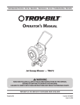
Operator’s Manual
FLEX™ Leaf Blower Attachment — 23AACAAX711
WARNING
READ AND FOLLOW ALL SAFETY RULES AND INSTRUCTIONS IN THIS MANUAL
BEFORE ATTEMPTING TO OPERATE THIS MACHINE.
FAILURE TO COMPLY WITH THESE INSTRUCTIONS MAY RESULT IN PERSONAL INJURY.
TROY-BILT LLC, P.O. BOX 361131 CLEVELAND, OHIO 44136-0019
Printed In USA
Form No. 769-10249
(February 4, 2015)
1
To The Owner
Thank You
Thank you for purchasing the Troy-Bilt FLEX™ Leaf Blower
Attachment. It was carefully engineered to provide excellent
performance when properly operated and maintained.
Please read this entire manual prior to operating the equipment.
It instructs you how to safely and easily set up, operate and
maintain your machine. Please be sure that you, and any other
persons who will operate the machine, carefully follow the
recommended safety practices at all times. Failure to do so could
result in personal injury or property damage.
If you have any problems or questions concerning the machine,
phone an authorized Troy-Bilt service dealer or contact us
directly. Troy-Bilt’s Customer Support telephone numbers,
website address and mailing address can be found on this page.
We want to ensure your complete satisfaction at all times.
Throughout this manual, all references to right and left side of the
machine are observed from the operating position.
All information in this manual is relative to the most recent
product information available at the time of printing. Review
this manual frequently to familiarize yourself with the machine,
its features and operation. Please be aware that this Operator’s
Manual may cover a range of product specifications for various
models. Characteristics and features discussed and/or illustrated
in this manual may not be applicable to all models. We reserve
the right to change product specifications, designs and
equipment without notice and without incurring obligation.
Table of Contents
Safe Operation Practices......................................... 3
Controls & Features.................................................. 6
Operation.................................................................. 8
Maintenance & Adjustment..................................11
Replacement Parts..................................................13
Warranty...................................................Back Cover
Record Product Information
Model Number
Before setting up and operating your new equipment, please
locate the model plate on the equipment and record the
information in the provided area to the right. You can locate
the model plate by looking at the rear of the attachment, on
the mounting plate. This information will be necessary, should
you seek technical support via our web site, Customer Support
Department, or with a local authorized service dealer.
Serial Number
Customer Support
Please do NOT return the machine to the retailer or dealer without first contacting the Customer Support Department.
If you have difficulty assembling this product or have any questions regarding the controls, operation, or maintenance of
this machine, you can seek help from the experts. Choose from the options below:
◊
Visit us on the web at www.troybilt.com
See How-to Maintenance and Parts Installation Videos at www.troybilt.com/tutorials
2
◊
Call a Customer Support Representative at (800) 828-5500 or (330) 558-7220
◊
Write to Troy-Bilt LLC • P.O. Box 361131 • Cleveland, OH • 44136-0019
Important Safe Operation Practices
2
WARNING! This symbol points out important safety instructions which, if not followed,
could endanger the personal safety and/or property of yourself and others. Read and follow
all instructions in this manual before attempting to operate this machine. Failure to comply
with these instructions may result in personal injury.
When you see this symbol. HEED ITS WARNING!
CALIFORNIA PROPOSITION 65
WARNING! Engine Exhaust, some of its constituents, and certain vehicle components
contain or emit chemicals known to State of California to cause cancer and birth defects
or other reproductive harm.
DANGER! This machine was built to be operated according to the safe operation practices in
this manual. As with any type of power equipment, carelessness or error on the part of the
operator can result in serious injury. This machine is capable of amputating fingers, hands,
toes and feet and throwing debris. Failure to observe the following safety instructions could
result in serious injury or death.
Operation
7.
Wear close fitting slacks and shirt. Shirt and slacks that
cover the arms and legs are recommended. Do not wear
loose fitting clothes or jewelry and secure hair so it is above
shoulder level. They can be caught in moving parts.
8.
Do not operate the machine while under the influence of
alcohol or drugs.
9.
Never place your hands or any part of your body or
clothing near rotating parts. Keep clear of the discharge
opening at all times. Never insert your hands, fingers,
feet, or any other part of your body or clothing into the
discharge or air intake openings as the rotating impeller
inside the housing can cause serious injury.
10.
Never operate machine without the plastic impeller
guard properly affixed to the machine. This device shields
the operator from accidental contact with the rotating
impeller.
11.
Keep all guards and safety devices in place and operating
properly.
General Operation:
1.
Read, understand, and follow all instructions on the
machine and in the manual(s) before attempting to
assemble and operate. Keep this manual in a safe place for
future and regular reference and for ordering replacement
parts.
2.
Be familiar with all controls and their proper operation.
Know how to stop the machine and disengage it quickly.
3.
Never allow children under 14 years of age to operate this
machine. Children 14 and over should read and understand
the instructions and safe operation practices in this manual
and on the machine and be trained and supervised by an
adult.
4.
This leaf blower is a powerful tool, not a plaything.
Therefore, exercise extreme caution at all times. It has been
designed to perform one job; to blow leaves. Do not use it
for any other purpose.
5.
Keep the area of operation clear of all persons, particularly
small children and pets. Stop the engine when they enter
the vicinity of the machine.
6.
Always wear safety glasses or safety goggles during
operation and while performing an adjustment or repair,
to protect eyes from debris or foreign objects that may be
thrown from machine.
12. Exercise caution when operating blower. Do not allow the
directional discharge chute to point in the direction of
bystanders or pets.
3
13.
If your machine should start making an unusual noise or
vibration, immediately stop the engine, disconnect the
spark plug wire and move the wire away from the spark
plug. Allow the machine to stop and perform the following
steps:
Service
1.
Never tamper with safety devices. Check their proper
operation regularly.
2.
Check all nuts, bolts and screws for proper tightness at
frequent intervals to keep the machine in safe working
condition. Also, visually inspect machine for any damage
and repair, if needed.
3.
Before cleaning, repairing, or inspecting, stop the engine
and make certain the impeller and all moving parts have
stopped. Disconnect the spark plug wire and ground it
against the engine to prevent unintended starting.
4.
16. Do not operate engine if air cleaner or cover over
carburetor air intake is removed, except for adjustment.
Removal of such parts could create a fire hazard.
Do not change the engine governor settings or overspeed
the engine. The governor controls the maximum safe
operating speed of the engine.
5.
Maintain or replace safety and instruction labels, as
necessary.
17.
6.
Never store the machine or fuel container near an open
flame, spark or pilot light such as on a water heater,
furnace, clothes dryer, or other gas appliances.
7.
Always refer to the operator’s manual for proper
instructions on off-season storage.
8.
According to the Consumer Products Safety Commission
(CPSC) and the U.S. Environmental Protection Agency (EPA),
this product has an Average Useful Life of seven (7) years,
or 70 hours of operation. At the end of the Average Useful
Life have the machine inspected annually by an authorized
service dealer to ensure that all mechanical and safety
systems are working properly and not worn excessively.
Failure to do so can result in accidents, injuries or death.
a.
Inspect for damage.
b.
Repair or replace any damaged parts.
c.
Check for any loose parts and tighten to assure
continued safe operation.
14. Muffler and engine become hot and can cause a burn. Do
not touch.
15.
Do not allow leaves or other debris to build up on engine’s
muffler. The debris could ignite and cause a fire.
Only use accessories approved for this machine by the
manufacturer. Read, understand, and follow all instructions
provided with the approved accessory.
18. Only operate machine in daylight or good artificial light.
Do not operate machine in dark areas where your vision
may be impaired.
19.
Never pick up or carry machine while the engine is running.
20.
If situations occur which are not covered in this manual,
use care and good judgment. Contact Customer Support
for assistance or the name of the nearest service dealer.
Children
Tragic accidents can occur if the operator is not alert to the
presence of small children. Children are often attracted to the
blowing activity. Never assume that children will remain where
you last saw them.
4
1.
Keep children out of the work area and under the watchful
eye of a responsible adult other than the operator.
2.
Be alert and turn the machine off if a child enters the area.
3.
Never allow children under the age of 14 to operate the
leaf blower.
Section 2 — Important Safe Operation Practices
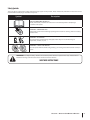
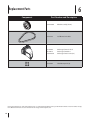
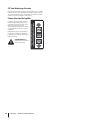
Safety Symbols
This page depicts and describes safety symbols that may appear on this product. Read, understand, and follow all instructions on the
machine before attempting to assemble and operate.
Symbol
Description
READ THE OPERATOR’S MANUAL(S)
Read, understand, and follow all instructions in the manual(s) before attempting to
assemble and operate.
WARNING— ROTATING BLADES
Keep hands out of inlet and discharge openings while machine is running. There are rotating
blades inside.
WARNING —BYSTANDERS
Do not stand in front of discharge. Keep bystanders away. Do not aim discharge at
bystanders, children, or pets.
WARNING— SHIELDS AND GUARDS
Do not operate without shields and guards (e.g. air intake guard and directional louvers) in
place.
WARNING! Your Responsibility—Restrict the use of this power machine to persons who read, understand and
follow the warnings and instructions in this manual and on the machine.
SAVE THESE INSTRUCTIONS!
Section 2 — Important Safe Operation Practices
5
3
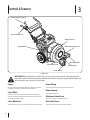
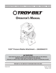
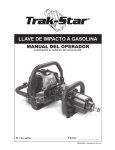
Controls & Features
Attachment Control Lever
Drive Control Lever
Blower Housing
Blower Directional Lever
Impeller Guard
Caster Wheel Lock
Discharge Chute
Grease Fitting
Caster Wheel
Figure 3-1
WARNING! Read and follow all safety rules and instructions in this manual, including the entire
Operation section, before attempting to operate this machine. Failure to comply with all safety rules
and instructions may result in personal injury.
Engine
Grease Fitting
Refer to the FLEX™ Power Base Operator’s Manual for details
regarding all engine-related controls and features.
Used to lubricate the caster wheel swivel function.
Caster Wheel
6
Blower Housing
Houses the blower fan.
The front caster wheel may be locked in a forward position,
or unlocked with the ability to swivel based on the operator’s
control of the handle system.
Attachment Control Lever
Caster Wheel Lock
Drive Control Lever
The caster lock is located on the top of the front caster wheel.
This lever propels the entire machine forward.
This lever activates the blower function.
900 Discharge Chute Attachment
The 900 discharge chute attachment is located on the left
side of the FLEX™ Leaf Blower Attachment and directs the air
flow forward. This is an optional feature to be utilized when a
redirection of the airflow is needed.
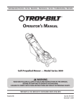
Blower Directional Lever
The air flow can be directed to one
of three directions using the blower
direction lever to reposition the
louvers.
WARNING! Do not stand
in front of discharge area.
AIR FLOW
UP
BLOWER DIRECTION LEVER
This lever controls the internal louvers
when used without the 900 discharge
chute attached. When the forward
discharge chute is attached, this lever
acts as a lock to hold the chute in place.
DOWN
Section 3 — Controls & Features
7
4
Operation
Starting & Stopping the Engine
Refer to the FLEX™ Power Base Operator’s Manual for instructions
on starting and stopping the engine.
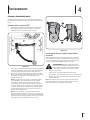
1
Connecting The FLEX™ Power Base
1.
With the kickstand UP on the FLEX™ Power Base unit,
as shown in Figure 4-1, roll it over to the leaf blower
attachment.
2
Figure 4-2
Uncouple the Leaf Blower Attachment from the Power Base:
Fully stop the power base engine before attempting to perform
any maintenance steps or uncoupling of the attachment. Never
attempt to uncouple the power base from the leaf blower
attachment WITH the engine running.
WARNING! Always turn off the FLEX™ Power Base
engine and remove the key prior to attempting to
perform any maintenance or uncoupling of the
power base from the attachment.
Figure 4-1
2.
3.
Tip the FLEX™ Power Base forward, engaging the top
mounting tab with the mounting handle on the leaf blower
attachment. See (1) of Figure 4-2.
Once the top mount is engaged (1), with both hands on the
handles, swiftly tip the power base backwards to engage
the bottom mounts (2). See Figure 4-2.
Note: The operator will be able to hear the lower mounts
engage and lock (latching sound) when coupled properly.
To test if coupled properly, lift up on the handles. If the unit
comes apart, the connection was not made. Double check
that the kickstand is still in the UP position, and swiftly tip
the power base backward with the top mount engaged.
Note: Once connected, the kickstand acts only as a locking
device for the attachment to the FLEX™ Power Base. The
only time the operator would need to deploy the kickstand
once connected to an attachment would be in the case of
uncoupling the FLEX™ Power Base from the attachment.
8
1.
Position the kickstand down.
2.
Tip the FLEX™ Power Base forward to disengage the
bottom mounts, then the top mount.
3.
Move the FLEX™ Power Base away from the leaf blower
attachment.
Note: With the kickstand deployed in the downward (unlocking)
position, the FLEX™ Power Base will rest comfortably in a parked
position.
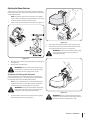
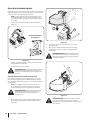
Adjusting the Blower Direction
The air flow can be directed to one of three directions using the
blower directional lever to move the louvers, when the discharge
chute is NOT attached.
NOTE: The blower directional lever must be in the middle
position when operating the blower with the 900 discharge
chute attachment to keep it locked into place.
1.
Pull the lever out and away from the blower. See Figure 4-3.
2
1
3
Figure 4-4
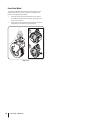
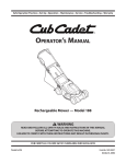
2.
Slide chute attachment downward, over the opening(2).
3.
Pivot the direction lever (3) to the middle position to lock
the chute attachment into place. See Figure 4-5.
WARNING! Keep hands out of inlet and discharge
openings while machine is running. There are
rotating blades inside.
Figure 4-3
2.
Move the lever to direct the airflow upward and downward.
See Figure 4-3.
3.
Release lever towards blower.
WARNING! Exercise caution when operating the
leaf blower. Do not allow the discharge opening to
point in the direction of bystanders or pets.
Attaching the 900 Discharge Chute Attachment
To redirect airflow to a 900 angle, which in this case would be
forward, during operation, a 900 discharge chute attachment is
included with your FLEX™ Leaf Blower Attachment.
Note: It is not required that the 900 Chute Attachment be
installed. This feature is to be utilized only if the operator
needs to redirect the blowing direction to forward.
WARNING! Always turn off the FLEX™ Power Base
engine and remove the key prior to attempting to
install the 900 discharge chute attachment.
1.
Pivot the blower direction lever all the way to the right (1),
into the highest position. See Figure 4-4.
Figure 4-5
WARNING! Exercise caution when operating the
leaf blower. Do not allow the 900 discharge chute to
point in the direction of bystanders or pets.
Section 4 — Operation
9
Front Caster Wheel
The FLEX™ Leaf Blower Attachment is equipped with a front
caster wheel. The caster can be locked in a straight ahead
position or allowed to swivel freely.
1.
Lift and place the pin into the forward hole for locked
or straight ahead operation and when operating across
slopes. See Figure 4-6.
2.
Place the pin in the rearward hole to allow the casters to
rotate freely for maneuvering around objects.
Figure 4-6
10
Section 4— Operation
5
Maintenance & Adjustments
Maintenance Schedule
Before
Each use
Check clutch bumpers
P
Check engine oil level
Clean debris
Lube Pivot Points
Maintenance
Every
8 Hours
Every
50 Hours
Every
200 Hours
P
P
P
P
3.
WARNING! Before lubricating, repairing, or
inspecting, always stop the engine on the FLEX™
Power Base, and remove the key to prevent
unintended starting of the engine.
Yearly
Prior
to Storing
P
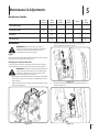
Remove the belt keeper, as shown in Figure 5-2, by
removing the hex bolt that secures it.
Engine
Refer to the FLEX™ Power Base’s Operators Manual for all engine
maintenance procedures and instructions.
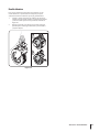
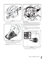
Changing the Leaf Blower Drive Belt
In the rare instance that the leaf blower drive belt may need to be
replaced, follow these instructions to perform this task yourself:
WARNING! Always turn off the FLEX™ Power Base
engine and remove the key prior to attempting to
perform any maintenance or uncoupling of the
power base from the attachment.
1.
Uncouple the FLEX™ Power Base from the FLEX™ Leaf Blower
Attachment, as per the instructions in the Operation section
of this manual.
2.
Remove the four tap screws that secure the top blower cover
as shown in Figure 5-1.
Figure 5-1
4.
Figure 5-2
Carefully work the belt off of the engine drive pulley as
shown in Figure 5-3.
Figure 5-3
11
5.
Remove the four upper tap screws that secure the mounting
frame bracket to the blower housing. See Figure 5-4.
Figure 5-6
Clutch Bumpers
Figure 5-4
6.
Pivot the mounting frame bracket down, as shown in
Figure 5-5.
It is necessary to check the clutch bumpers, installed on the
dog clutch assembly, before each use. The clutch bumpers are
wearable parts that will need to be replaced periodically after
extended usage.
To replace the clutch bumpers, follow these instructions:
1.
Gently pry each clutch bumper out of the dog clutch using
a standard screw driver. See Figure 5-7.
Figure 5-5
12
7.
Remove the belt from the drive pulley assembly, as shown
in Figure 5-6, by working the belt off of the two drive
pulleys.
8.
Replace the belt and reassemble the attachment in the
reverse order.
Section 5 — Maintenance & Adjustments
2.
Figure 5-7
Replace the clutch bumpers (Kit Part No. 753-08457) by
fully pressing them into place.
Lubrication
WARNING! Before lubricating, repairing, or
inspecting, always stop the engine on the FLEX™
Power Base, and remove the key to prevent
unintended starting of the engine.
Blower Directional Lever and Louvers
Lubricate the blower directional lever, and louvers, once per
season with light oil.
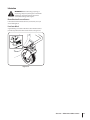
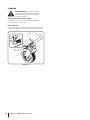
Front Caster Wheel
A grease fitting is located on the front caster wheel mount to
provide easy lubrication of the caster wheel. See Figure 5-8.
Figure 5-8
Section 5 — Maintenance & Adjustments
13
6
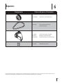
Replacement Parts
Component
Part Number and Description
634-04497A
Wheel Assembly (Front)
954-04123
Leaf Blower Drive Belt
631-04253 781-04175 710-04373A
Discharge Chute w/ Label
Discharge Chute Base
Discharge Chute Screws (3x)
753-08457
Clutch Bumper Kit (6)
Phone (800) 828-5500 to order replacement parts or a complete Parts Manual (have your full model number and serial number ready).
Parts Manual downloads are also available free of charge at www.troybilt.com.
14
Notes
7
15
16
Section 7— Notes
LIMITED WARRANTY FOR FLEX ATTACHMENT PRODUCT
The limited warranty set forth herein is given by Troy-Bilt LLC to the Initial
Purchaser (as defined herein) with respect to a new Troy-Bilt-branded FLEX
attachment product consisting of one of the following four (4) attachments
to the FLEX Power Base (referred to hereafter as the “Attachment”): (i) wide
area mower, (ii) snow-thrower, (iii) pressure washer or (iv) leaf blower. This
limited warranty does not cover Emission Control Systems and is not a
Federal Emission Control Warranty Statement as defined by U.S. federal
law. Please refer to the Federal Emission Control Warranty Statement in
the operator’s manual for the FLEX Power Base product (“Power Base”) for
warranties covering Emission Control Systems.
Scope of the Limited Warranty
Troy-Bilt LLC offers the following limited warranty to the Initial Purchaser for
residential or otherwise non-commercial use of the Attachment on the FLEX
Power Base: except for the Exclusions (defined herein), during the Warranty
Period (defined herein), the Attachment will be free from manufacturing
defects (including workmanship and materials). The “Initial Purchaser” is the
first person to purchase a new Attachment from an authorized Troy-Bilt dealer,
distributor and/or retailer of such attachment products. This limited warranty
is non-transferrable. Except as otherwise set forth herein, the limited warranty
period for this new Attachment purchased by the Initial Purchaser is two (2)
years from the date of purchase as shown on the original sales receipt for the
Attachment (“Warranty Period”).
Defects in Workmanship or Materials
Except for the Exclusions, the Attachment is warranted to be free from
manufacturing defects in either workmanship or materials for the Warranty
Period. During the Warranty Period, Troy-Bilt LLC will, at its option, either
repair or replace any original part that is covered by this limited warranty and
is determined to be defective in workmanship or material.
To qualify for this limited warranty the FLEX™ Base Unit:
1.
Must have been purchased from an authorized Troy-Bilt retailer.
2.
Must have been purchased within the United States by the Initial
Purchaser.
3.
Must have been used for residential or otherwise non-commercial
purposes.
4.
Must have been used in a manner consistent with the normal and
proper intended use for the Attachment. This Attachment is not
intended for rental or commercial use.
Who can perform repairs under this warranty?
In order to qualify for the limited warranty as set forth herein, the repairs made
under this warranty must be performed by an authorized Troy-Bilt service
provider.
How to get service under this limited warranty:
To locate a Troy-Bilt warranty service provider, contact your authorized
Troy-Bilt dealer, distributor and/or retailer or contact Troy-Bilt LLC at P.O. Box
361131, Cleveland, Ohio 44136-0019 or call 1-877-282-8684 or log on to our
Website at www.troybilt.com. This limited product warranty is provided
by Troy-Bilt LLC and is the only product warranty provided by Troy-Bilt LLC
for this Attachment. A COPY OF YOUR SALES RECEIPT IS REQUIRED FOR
WARRANTY SERVICE.
What this limited warranty does not cover.
This limited warranty does not cover the following (the “Exclusions”):
1.
Attachment purchased outside of the United States.
2.
Damage due to lack of maintenance and/or improper maintenance as
described in the operator’s manual.
3.
Normal wear and tear resulting from use of the Attachment.
4.
Use of the Attachment that is not consistent with the intended use
thereof as described in the operating instructions, including, but not
limited to, abuse, misuse and/or neglect of the Attachment or any use
inconsistent with and/or non-compliant with instructions contained in
the Operator’s Manual.
5.
Any expendable, consumable, or routine maintenance item which
needs replacement or service as part of normal maintenance, unless
such items have defects that cause failure or premature wear within
the first thirty (30) days. Where applicable, normal wear items include
but are not limited to, blades, tires, belts, filters, fuses, and other
consumable items
6.
Any Attachment that has been altered or modified in a manner not
consistent with the original design of the product or in a manner not
otherwise approved by Troy-Bilt LLC.
7.
Paint repairs or replacements for defective paint (including materials
and application) are covered for a period of three (3) months.
8.
Wheel rims are covered for a period of three (3) months for
manufacturing defects.
9.
The FLEX Power Base is covered by a separate limited warranty which
is contained in the operator’s manual for the FLEX Power Base.
This warranty does not cover and Troy-Bilt LLC disclaims any
responsibility for:
1.
Loss of time or loss of use of the Attachment.
2.
Transportation costs and other expenses incurred in connection with
the transport of the Attachment to and from the authorized Troy-Bilt
service provider.
3.
Any loss or damage to other equipment or personal items.
4.
Damage caused by performance or use of the Attachment in
connection with any product other than the FLEX Power Base.
Limitations:
1.
THERE ARE NO IMPLIED WARRANTIES, INCLUDING, BUT NOT LIMITED
TO, ANY IMPLIED WARRANTY OF MERCHANTABILITY OR FITNESS FOR A
PARTICULAR PURPOSE. NO WARRANTY APPLIES AFTER THE APPLICABLE
WARRANTY PERIOD AS SET FORTH ABOVE AS TO THE PARTS AS
IDENTIFIED. NO OTHER EXPRESS WARRANTY OR GUARANTY, WHETHER
WRITTEN OR ORAL, EXCEPT AS MENTIONED ABOVE, GIVEN BY ANY
PERSON OR ENTITY, INCLUDING A DEALER OR RETAILER, WITH RESPECT
TO ANY PRODUCT SHALL BIND TROY-BILT LLC. DURING THE WARRANTY
PERIOD, THE EXCLUSIVE REMEDY IS REPAIR OR REPLACEMENT OF THE
DEFECTIVE PART, AS SET FORTH ABOVE. (SOME STATES DO NOT ALLOW
LIMITATIONS ON HOW LONG AN IMPLIED WARRANTY LASTS, SO THE
ABOVE LIMITATION MAY NOT APPLY TO YOU.)
2.
THE PROVISIONS AS SET FORTH HEREIN PROVIDE THE SOLE AND
EXCLUSIVE REMEDY ARISING FROM THE SALE. TROY-BILT SHALL NOT
BE LIABLE FOR INCIDENTAL OR CONSEQUENTIAL LOSS OR DAMAGES
INCLUDING, WITHOUT LIMITATION, FOR TRANSPORTATION OR FOR
RELATED EXPENSES, OR FOR RENTAL EXPENSES TO TEMPORARILY
REPLACE A WARRANTED PRODUCT. (SOME STATES DO NOT ALLOW
THE EXCLUSION OR LIMITATION OF INCIDENTAL OR CONSEQUENTIAL
DAMAGES, SO THE ABOVE EXCLUSION OR LIMITATION MAY NOT APPLY
TO YOU.)
3.
In no event shall recovery of any kind be greater than the amount of the
purchase price of the product sold. Alteration of the safety features of the
product shall void this limited warranty. You assume the risk and liability
for loss, damage, or injury to you and your property and/or to others
and their property arising out of the use or misuse or inability to use the
product.
How State Law Relates to this Warranty:
This limited warranty gives you specific legal rights, and you may also have
other rights which vary from state to state.
Troy-Bilt LLC, P.O. BOX 361131 CLEVELAND, OHIO 44136-0019; Phone: 1-800-828-5500, 1-330-558-7220
MTD Canada Limited - KITCHENER, ON N2G 4J1; Phone 1-800-668-1238
079221 REV. A
Normas de seguridad • Controles y características • Funcionamiento • Mantenimiento • Garantía
Manual del Operador
Accesorio soplador de hojas FLEX™ — 23AACAAX711
ADVERTENCIA
LEA Y OBSERVE TODAS LAS NORMAS E INSTRUCCIONES DE SEGURIDAD INCLUIDAS
EN ESTE MANUAL ANTES DE PONER EN FUNCIONAMIENTO LA MÁQUINA.
SI NO SIGUE ESTAS INSTRUCCIONES PUEDE PROVOCAR LESIONES PERSONALES.
TROY-BILT LLC, P.O. BOX 361131 CLEVELAND, OHIO 44136-0019
Impreso en EE.UU.
1
Al propietario
Gracias
Gracias por comprar el Accesorio soplador de hojas FLEX™ Troy-Bilt.
El mismo ha sido cuidadosamente diseñado para brindar excelente
rendimiento si se lo opera y mantiene correctamente.
Por favor lea todo este manual antes de hacer funcionar el equipo.
El manual le indica cómo configurar, operar y mantener la máquina de
manera fácil y segura. Por favor asegúrese de que usted, y cualquier
otra persona que haga funcionar la máquina, sigue atentamente y en
todo momento las medidas de seguridad recomendadas. En caso de
no hacerlo podrían producirse lesiones personales o daños materiales.
Si tiene algún problema o duda respecto a la máquina, llame a
un distribuidor de servicio Troy-Bilt autorizado o comuníquese
directamente con nosotros. En esta página encontrará los números
de teléfono, dirección del sitio web y dirección postal de Atención
al cliente de Troy-Bilt. Queremos garantizar su entera satisfacción
en todo momento.
En este manual, todas las referencias al lado derecho e izquierdo
de la máquina se observan desde la posición del operador
Toda la información contenida en este manual hace referencia a la
más reciente información de producto disponible en el momento de
la impresión. Revise el manual frecuentemente para familiarizarse
con la máquina, sus características y funcionamiento. Por favor tenga
en cuenta que este Manual del Operador puede cubrir una gama de
especificaciones para productos de varios modelos. Es posible que
las características y funciones incluidas y/o ilustradas en este manual
no se apliquen a todos los modelos. Nos reservamos el derecho de
modificar las especificaciones de los productos, diseños y equipos
sin previo aviso y sin generar responsabilidad por obligaciones de
ningún tipo.
Índice
Medidas de seguridad............................................... 20
Controles y Características........................................ 23
Funcionamiento......................................................... 25
Mantenimiento y ajustes........................................... 28
Repuestos.................................................................... 31
Garantía...................................................................... 32
Registro de información de producto
Número de modelo
Antes de configurar y hacer funcionar su equipo nuevo, por favor
localice la placa de modelo en el equipo y registre la información
en el espacio de la derecha. Podrá localizar la placa de modelo si
la busca en la parte posterior del accesorio, en la placa de montaje.
Si tiene que solicitar soporte técnico a través de nuestro sitio web,
el Departamento de Asistencia al Cliente, o de un distribuidor de
servicio autorizado local, necesitará esta información
Número de serie
Asistencia al Cliente
Por favor, NO devuelva la máquina al minorista o distribuidor sin ponerse en contacto primero
con el Departamento de Asistencia al Cliente.
Si tiene dificultad para armar este producto o tiene dudas respecto a los controles, el funcionamiento o el mantenimiento
de esta máquina, puede solicitar la ayuda de expertos. Seleccione una de las opciones siguientes:
◊
Visite nuestro sitio web en www.troybilt.com
Vea videos instructivos sobre el mantenimiento y la instalación de piezas en www.troybilt.com/tutorials
◊
Llame a un representante de Asistencia al Cliente al (800) 828-5500 ó (330) 558-7220
◊
Escriba a Troy-Bilt LLC • P.O. Box 361131 • Cleveland, OH • 44136-0019
19
2
Importantes medidas de seguridad
¡ADVERTENCIA! La presencia de este símbolo indica que se trata de instrucciones de seguridad
importantes que se deben respetar para evitar poner en peligro su seguridad personal y/o material
y la de otras personas. Lea y cumpla todas las instrucciones de este manual antes de intentar operar
esta máquina. Si no respeta estas instrucciones puede provocar lesiones personales.
Cuando vea este símbolo. ¡TENGA EN CUENTA LA ADVERTENCIA!
PROPOSICIÓN 65 DE CALIFORNIA
¡ADVERTENCIA! El escape del motor, algunos de los elementos del mismo y algunos
componentes del vehículo contienen o liberan sustancias químicas que según el Estado
de California pueden producir cáncer, defectos de nacimiento u otros problemas reproductivos.
¡PELIGRO! Esta máquina está diseñada para ser utilizada respetando las normas de seguridad
contenidas en este manual. Al igual que con cualquier tipo de equipo motorizado, un descuido
o error por parte del operador puede producir lesiones graves. Esta máquina es capaz de amputar
dedos, manos y pies y de arrojar residuos. De no respetar las instrucciones de seguridad siguientes
se pueden ocasionar lesiones graves o la muerte.
Funcionamiento
7.
Use pantalones y camisa ajustados. Se recomienda el uso de
camisa y pantalón que cubran los brazos y las piernas. No use
vestimenta suelta ni alhajas y átese el cabello de modo que
quede por encima del hombro. Pueden quedar atrapados en
las partes móviles.
8.
No haga funcionar la máquinas si se encuentra bajo los efectos
del alcohol o las drogas.
9.
No coloque nunca las manos ni ninguna parte del cuerpo
o vestimenta cerca de las piezas rotatorias. Manténgase lejos
de la abertura de descarga en todo momento. No inserte nunca
las manos, dedos, pies ni ninguna otra parte del cuerpo ni la
vestimenta dentro de las aberturas de descarga o de toma
de aire ya que el motor rotatorio del interior del alojamiento
puede causar lesiones graves.
Funcionamiento general:
1.
2.
Familiarícese con todos los controles y con el uso adecuado
de los mismos. Sepa cómo detener la máquina y desactivarla
rápidamente.
3.
No permita nunca que los niños menores de 14 años utilicen
esta máquina. Los niños de 14 años en adelante deben
leer y entender las instrucciones y las normas de seguridad
contenidas en este manual y en la máquina y deben ser
entrenados y supervisados por un adulto.
10.
Su soplador de hojas es una herramienta potente, no un
juguete. Por lo tanto, tenga mucho cuidado en todo momento.
Esta unidad ha sido diseñada para realizar una tarea: soplar las
hojas. No la utilice para ningún otro fin.
No opere nunca la máquina sin el protector plástico
adecuadamente instalados en la misma. Este dispositivo
protege al operador del contacto accidental con el motor
rotatorio.
11.
Mantenga todos los protectores y dispositivos de seguridad
en su lugar y en buenas condiciones.
12.
Cuando opere el soplador tenga precaución. No permita que
la descarga esté orientada hacia los transeúntes o mascotas.
4.
20
Lea, entienda y cumpla todas las instrucciones incluidas en
la máquina y en el(los) manual(es) antes de intentar realizar
el montaje de la unidad y utilizarla. Guarde este manual en
un lugar seguro para consultas futuras y periódicas, así
como para solicitar repuestos.
5.
Mantenga el área de operación despejada de personas,
especialmente niños pequeños y mascotas. Detenga el
motor cuando haya niños o mascotas cerca de la unidad.
6.
Use siempre anteojos o antiparras de seguridad durante el
funcionamiento del soplador y mientras realiza algún ajuste
o reparación para protegerse los ojos de los residuos u
objetos extraños que podrían ser arrojados por la máquina.
13.
Si su máquina hace algún sonido o vibración inusual al
arrancar, detenga el motor inmediatamente, desconecte
el cable de la bujía y retire el cable de la bujía. Deje que la
máquina se detenga y realice los siguientes pasos:
a.
Inspeccione la máquina para ver si está dañada.
b.
Repare o reemplace las piezas dañadas.
c.
Controle si hay piezas flojas y ajústelas para asegurar
que la máquina funcione de manera segura y continua.
14.
El silenciador y el motor se calientan y pueden causar
quemaduras. No los toque.
15.
No permita que se acumulen hojas ni otros residuos sobre
el silenciador del motor. Los residuos podrían encenderse
y dar lugar a un incendio.
16.
No haga funcionar el motor si se han retirado el filtro de aire
o la tapa que está encima de la toma de aire del carburador,
a menos que sea para un ajuste. La falta de esas piezas podría
generar un peligro de incendio.
17.
Utilice solamente accesorios aprobados para esta máquina
por el fabricante original. Lea, comprenda y siga todas las
instrucciones proporcionadas con los accesorios aprobados.
18.
Utilice la máquina únicamente con luz de día o con una buena
luz artificial. No opere la unidad en áreas oscuras en las cuales
la visibilidad se puede ver afectada.
19.
Nunca levante o cargue la máquina cuando el motor
esté encendido.
20.
Si se presentan situaciones que no están previstas en este
manual, tenga cuidado y use el sentido común. Comuníquese
con Atención al cliente para solicitar ayuda o el nombre del
distribuidor de servicio más cercano.
Niños
Pueden ocurrir accidentes trágicos si el operador no está atento
a la presencia de niños. La actividad del soplador a menudo resulta
atractiva para los niños. Nunca suponga que los niños permanecerán
en el lugar donde los vio por última vez.
1.
Mantenga a los niños fuera del área de trabajo y bajo estricta
vigilancia de un adulto responsable además del operador.
2.
Esté alerta y apague la máquina si un niño ingresa al área.
3.
No permita nunca que los niños menores de 14 años utilicen
este motor.
Servicio
1.
Nunca altere los dispositivos de seguridad.
Controle periódicamente que funcionen correctamente.
2.
Controle frecuentemente que todas las tuercas, los pernos y
tornillos estén bien ajustados para comprobar que la máquina
se encuentra en condiciones seguras de funcionamiento.
Además, realice una inspección visual de la máquina para
controlar si la misma está dañada y repárela de ser necesario.
3.
Antes de limpiar, reparar o inspeccionar la máquina, detenga
el motor y compruebe que el impulsor y todas las partes
móviles se hayan detenido. Desconecte el cable de la bujía
y póngalo haciendo masa contra el motor para evitar que
se encienda accidentalmente.
4.
No cambie la configuración del regulador del motor ni acelere
demasiado el motor. El regulador del motor controla la
velocidad máxima de funcionamiento seguro del motor.
5.
Mantenga o reemplace las etiquetas de seguridad y de
instrucciones según sea necesario.
6.
Nunca almacene la máquina o el recipiente de combustible
cerca de llama expuesta, chispas o aparatos con piloto como
por ejemplo, calentadores de agua, hornos, secadores de
ropa u otros aparatos a gas.
7.
Consulte siempre el manual del operador para obtener
instrucciones adecuadas para el almacenamiento fuera
de temporada.
8.
Según la Comisión de Seguridad de Productos para el
Consumidor de los Estados Unidos (CPSC) y la Agencia
de Protección Ambiental de los Estados Unidos (EPA),
este producto tiene una vida útil media de siete (7) años
ó 70 horas de funcionamiento. Al finalizar la vida útil media
haga inspeccionar anualmente esta unidad por un distribuidor
de servicio autorizado para cerciorarse de que todos los
sistemas mecánicos y de seguridad funcionan correctamente
y no tienen excesivo desgaste. Si no lo hace, puede ocasionar
accidentes, lesiones o la muerte.
Sección 2 — Importantes medidas de seguridad
21
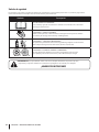
Símbolos de seguridad
En esta página se presentan y describen los símbolos de seguridad que en este producto puede tener. Lea, entienda y siga todas las
instrucciones incluidas en la máquina antes de intentar armarla y hacerla funcionar.
Símbolo
Descripción
LEA LOS MANUALES DEL OPERADOR
Lea, entienda y siga todas las instrucciones incluidas en los manuales antes de intentar
armarla y hacerla funcionar.
ADVERTENCIA – CUCHILLAS GIRATORIAS
Mientras la máquina está en funcionamiento, mantenga las manos lejos de las aberturas
de entrada y de descarga. En el interior hay cuchillas giratorias.
ADVERTENCIA — PRESENCIA DE OBSERVADORES
No permanezca parado frente al área de descarga. Mantenga alejados a los observadores.
Nunca dirija la descarga hacia los observadores, los niños o las mascotas.
ADVERTENCIA - ESCUDOS DE SEGURIDAD Y PROTECCIONES
No haga funcionar la máquina sin los escudos de seguridad y las protecciones
(por ejemplo, protector de la toma de aire y aletas direccionales) en su lugar.
¡ADVERTENCIA! Su responsabilidad—Limite el uso de esta máquina motorizada a las personas que lean,
comprendan y respeten las advertencias e instrucciones que figuran en este manual y en la máquina.
¡GUARDE ESTAS INSTRUCCIONES!
22
Sección 2 — Importantes medidas de seguridad
3
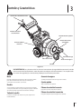
Controles y Características
Palanca de control del accesorio
Palanca de control
de transmisión
Alojamiento del soplador
Palanca direccional
del soplador
Protector plástico
del motor
Canal de descarga
Traba de la ruedita
Accesorio de engrase
Ruedita
Figura 3-1
¡ADVERTENCIA! Lea y observe todas las normas e instrucciones de seguridad de este manual, incluida
toda la sección de funcionamiento, antes de poner esta máquina en funcionamiento. Si no respeta todas
las normas de seguridad y las instrucciones puede provocar lesiones personales.
Motor
Accesorio de engrase
Consulte el manual del operador de la base de potencia FLEX™
para obtener información sobre todos los controles y las
características relacionados con el motor.
Se utiliza para lubricar la función de giro de la ruedita.
Ruedita
Aloja el ventilador del soplador.
Se puede trabar la ruedita delantera en posición hacia adelante
o se la puede destrabar con la capacidad para que gire en función
del control que haga el operador del sistema de la manija.
Traba de la ruedita
La traba de la ruedita está ubicada en la parte superior de la
ruedita delantera.
Caja de soplado
Palanca de control del accesorio
Esta palanca activa la función del soplador.
Palanca de control de transmisión
Esta palanca impulsa toda la máquina hacia adelante.
23
900 Canal de descarga, Accesorio
El accesorio de canal de descarga de 900 está ubicado en el costado
izquierdo del Accesorio soplador de hojas FLEX™ y dirige el caudal
de aire hacia adelante. Es una característica opcional que se utiliza
cuando es necesario redirigir el caudal de aire.
Palanca direccional del soplador
El flujo de aire puede ser orientado en
una de las tres direcciones utilizando
la palanca direccional del soplador para
reubicar las aletas.
¡ADVERTENCIA! No
permanezca parado frente
al área de descarga.
24
CAUDAL
DE AIRE
AIR FLOW
UP
ARRIBA
PALANCA
DIRECCIONAL
DEL SOPLADOR
BLOWER
DIRECTION
LEVER
La palanca controla las aletas internas
cuando se usa la unidad sin que esté
conectado el canal de descarga de 900 .
Cuando está colocado el canal
de descarga hacia adelante, esta palanca
actúa como traba para retener el canal
en su lugar.
Sección 3 — Controles y Características
ABAJO
DOWN
4
Funcionamiento
Arranque y detención del motor
Consulte el manual del operador de la base de potencia FLEX™ a
fin de obtener las instrucciones para el arranque y la detención del
motor.
1
Conexión de la base de potencia FLEX™
1.
Con el soporte en la posición UP (arriba) en la unidad de la
base de potencia FLEX™, como se indica en la Figura 4-1,
hágalo girar hacia el accesorio soplador de hojas.
2
Figura 4-2
Para desacoplar el accesorio soplador de hojas de la base
de potencia:
Pare completamente el motor de la base de potencia antes de
intentar realizar los pasos de mantenimiento o de desacoplar el
accesorio. No intente nunca desacoplar la base de potencia del
accesorio soplador de hojas CON el motor en marcha.
¡ADVERTENCIA! Apague siempre el motor de
la base de potencia FLEX™ y saque la llave antes de
intentar realizar cualquier tarea de mantenimiento
o desacople de la base de potencia del accesorio.
Figura 4-1
2.
3.
Incline la base de potencia FLEX™ hacia adelante, enganchando
la lengüeta de montaje superior con la manija de montaje del
accesorio soplador de hojas. Consulte 1 de la Figura 4-2.
Una vez que se engancha el montaje superior (1), con ambas
manos en las manijas, incline suavemente la base de potencia
hacia atrás para enganchar los montajes inferiores (2).
Consulte la Figura 4-2.
Nota: El operador podrá oír cuando se enganchan y traban
(sonido al trabarse) los montajes inferiores si se realiza el
acoplamiento correctamente. Para probar si se acopló
correctamente, tire de las manijas hacia arriba. Si la unidad
se separa, significa que no se estableció la conexión. Vuelva
a controlar que el soporte esté aún en la posición UP (arriba)
e incline suavemente la base de potencia hacia atrás con el
montaje inferior enganchado.
1.
Ponga el soporte abajo.
2.
Incline la base de potencia FLEX™ hacia adelante para
desenganchar los montajes inferiores, luego el montaje superior.
3.
Mueva la base de potencia FLEX™ para alejarla del accesorio
soplador de hojas.
Nota: Con el soporte en la posición en que queda hacia abajo
(para destrabar), la base de potencia FLEX™ quedará apoyada
de manera conveniente en posición de detención.
Nota: Una vez conectado, el soporte actúa únicamente
como dispositivo que traba el accesorio a la base de potencia
FLEX™. En la única ocasión que el operador necesita utilizar el
soporte una vez que lo haya conectado a un accesorio, es para
desacoplar la base de potencia FLEX™ del accesorio.
25
Ajuste de la dirección del soplador
El flujo de aire puede ser direccionado en una de las tres direcciones
utilizando la palanca direccional del soplador para mover las aletas,
cuando el canal de descarga NO está conectado.
NOTA: La palanca de dirección del soplador debe estar en
la posición intermedia cuando se opera el soplador con el
accesorio del canal de descarga de 900 para mantenerlo fijo
en su lugar.
1.
Tire de la palanca hacia afuera del soplador. Consulte la
Figura 4-3.
2
1
3
Palanca direccional
del soplador
Figura 4-4
Aletas
Vista lateral
2.
Deslice el accesorio del canal hacia abajo, por encima
de la abertura(2).
3.
Gire la palanca direccional (3) hasta la posición media
para trabar el accesorio de canal en su lugar. Consulte
la Figura 4-5.
¡ADVERTENCIA! Mientras la máquina está en
funcionamiento mantenga las manos fuera de las
aberturas de entrada y de descarga. En el interior
hay cuchillas giratorias.
Figura 4-3
2.
Mueva la palanca para dirigir el caudal de aire hacia arriba
y abajo. Consulte la Figura 4-3.
3.
Libere la palanca hacia el soplador.
¡ADVERTENCIA! Actúe con precaución al operar el
soplador de hojas. No permita que la abertura de
descarga esté orientada hacia los observadores o las
mascotas.
Conexión del accesorio de canal de descarga de 900
Para redirigir el caudal de aire en un ángulo de 900, que en este
caso sería hacia adelante, durante el funcionamiento, se incluye
un accesorio de canal de descarga de 900 con el accesorio soplador
de hojas FLEX™.
Nota: No es obligatorio instalar el accesorio de canal
de 900. Esta función sólo debe utilizarse si el operador
necesita redirigir la dirección de soplado hacia adelante.
¡ADVERTENCIA! Apague siempre el motor de
la base de potencia FLEX™ y saque la llave antes
de intentar instalar el accesorio de canal de
descarga de 900.
1.
26
Gire la palanca direccional del soplador totalmente hacia
la derecha (1), hasta la posición más elevada. Consulte la
Figura 4-4.
Sección 4 — Funcionamiento
Figura 4-5
¡ADVERTENCIA! Actúe con precaución al operar
el soplador de hojas. No permita que el canal de
descarga de 900 esté orientado hacia los observadores
o las mascotas.
Ruedita delantera
El accesorio soplador de hojas FLEX™ está equipado con una
ruedita delantera. Se puede trabar la rueda para que quede
orientada derecha hacia adelante o para que gire libremente.
1.
Levante y coloque el pasador en el orificio que está hacia
adelante para que quede trabada u orientada hacia adelante
y cuando se utilice para atravesar pendientes. Consulte la
Figura 4-6.
2.
Coloque el pasador en el orificio que está hacia atrás para
permitir que las rueditas giren libremente para maniobrar
y esquivar objetos.
Figura 4-6
Sección 4 — Funcionamiento
27
5
Mantenimiento y Ajustes
Mantenimiento
¡ADVERTENCIA! Antes de lubricar, reparar
o inspeccionar, pare siempre el motor de la base
de potencia FLEX™ y retire la llave, para evitar
el arranque accidental.
Motor
Consulte el manual del operador de la base de potencia FLEX™
para obtener todos los procedimientos y las instrucciones para
el mantenimiento del motor.
Cambio de la correa de transmisión del soplador de hojas
En el extraño caso en que fuera necesario cambiar la correa de
transmisión del soplador de hojas, siga estas instrucciones para
realizar esta tarea usted mismo:
¡ADVERTENCIA! Apague siempre el motor de
la base de potencia FLEX™ y saque la llave antes de
intentar realizar cualquier tarea de mantenimiento
o desacople de la base de potencia del accesorio.
1.
2.
Desacople la base de potencia FLEX™ del accesorio soplador de
hojas FLEX™, de acuerdo con las instrucciones que se incluyen
en la sección Funcionamiento del presente manual.
Figura 5-2
4.
Saque con cuidado la correa de la polea de transmisión
del motor como se indica en la Figura 5-3.
5.
Extraiga los cuatro tornillos roscados superiores que sujetan
el soporte del bastidor de montaje al alojamiento del soplador.
Consulte la Figura 5-4.
Extraiga los cuatro tornillos roscados que sujetan la cubierta
superior del soplador como se indica en la Figura 5-1.
Figura 5-3
Figure 5-1
3.
28
Extraiga el guardacorrea, como se indica en la Figura 5-2,
para lo que debe extraer el perno hexagonal que lo sujeta.
Figura 5-4
6.
Gire el soporte del bastidor de montaje hacia abajo, como
se indica en la Figura 5-5.
Figura 5-6
Embrague Bumpers
Es necesario comprobar los parachoques de embrague, instalados
en el conjunto de embrague de perro, antes de cada uso. Los
topes de embrague son partes de consumo que tendrán que ser
reemplazados periódicamente después de un uso prolongado.
Para volver a colocar los topes de embrague, siga estas
instrucciones:
9.
Haga palanca suavemente cada tope de embrague del
embrague de garras con un destornillador estándar. En la
ilustración 5-7.
Figura 5-5
7.
Extraiga la correa del conjunto de la polea de transmisión,
como se indica en la Figura 5-6, para lo que debe sacar la
correa de las dos poleas de transmisión.
8.
Reemplace la correa y vuelva a armar el accesorio siguiendo
el orden inverso.
10.
Figure 5-7
Vuelva a colocar los topes de embrague Kit (Parte No. 75308457) por ellos pulsar a tope en su lugar.
Sección 5 — Mantenimiento y Ajustes
29
Lubricación
¡ADVERTENCIA! Antes de lubricar, reparar
o inspeccionar, pare siempre el motor de la base
de potencia FLEX™ y retire la llave, para evitar
el arranque accidental.
Aletas y palanca direccional del soplador
Lubrique la palanca direccional y las aletas del soplador una
vez por temporada con aceite ligero.
Ruedita delantera
Se coloca un engrasador en el montaje de la ruedita delantera para
brindar una fácil lubricación de dicha ruedita. Consulte la Figura 5-8.
Figura 5-8
30
Sección 5 — Mantenimiento y Ajustes
6
Repuestos
Componente
Número de pieza y Descripción
634-04497A
Conjunto de rueda (delantera)
954-04123Correa de transmisión del
soplador de hojas
631-04253 781-04175 710-04373A
Canal de descarga c/ etiqueta
Base del canal de descarga
Tornillos (3x) del canal de descarga
753-08457
Clutch Bumper Kit (6)
Llame al (800) 828-5500 para solicitar repuestos o un Manual de Piezas completo (tenga a mano el número de modelo y número de serie
completo). En www.troybilt.com también podrá descargar el Manual de Repuestos sin cargo alguno.
31
GARANTÍA LIMITADA PARA EL ACCESORIO FLEX
La garantía limitada que se estable en el presente documento es otorgada
por Troy-Bilt LLC al comprador inicial (como se define en este documento)
en relación con el nuevo accesorio FLEX Troy-Bilt que está integrado por uno
de los siguientes cuatro (4) accesorios de la base de potencia FLEX (identificado
en adelante como el "Accesorio"): (i) cortadora de césped con capacidad para
superficies amplias, (ii) máquina quitanieve, (iii) lavadora a presión
o (iv) soplador de hojas. La presente garantía limitada no cubre los Sistemas
de control de emisiones y no constituye una Declaración de garantía del control
de las emisiones federal según lo definido por las leyes federales de los Estados
Unidos. Consulte la Declaración de garantía del control de las emisiones federal
que se incluye en el manual del operador de la base de potencia FLEX
("Base de potencia") para conocer las garantías que cubren los Sistemas
de control de emisiones.
Alcance de la Garantía limitada
Troy-Bilt LLC ofrece la siguiente garantía limitada al Comprador Inicial para uso
residencial u otro tipo de uso no comercial del accesorio de la base de potencia
FLEX: excepto por las Exclusiones (que se definen en el presente documento),
durante el Período de la Garantía (como se define en este documento), el
Accesorio estará libre de defectos de fabricación (que incluyen la mano de obra y
los materiales). El “Comprador inicial” es la primera persona en adquirir un nuevo
Accesorio a un representante, distribuidor y/o minorista Troy-Bilt autorizado
del mencionado accesorio. La garantía limitada es intransferible. Excepto que
se disponga lo contrario en el presente documento, el período de la garantía
limitada para este nuevo Accesorio adquirido por el Comprador inicial es de dos
(2) años a partir de la fecha de la compra, como se indica en el comprobante de
ventas original correspondiente al Accesorio (“Período de la Garantía”).
Defectos en la mano de obra o en los materiales
Excepto por las Exclusiones, se garantiza que el Accesorio estará libre de defectos
de fabricación en la mano de obra o los materiales durante el Período de la Garantía.
Durante el Período de la Garantía, Troy-Bilt LLC reparará o reemplazará, a su juicio,
cualquier pieza original que esté cubierta por la presente garantía limitada y que se
determine que presenta algún defecto en la mano de obra o los materiales.
A fin de reunir los requisitos para la presente garantía limitada, la Unidad
Base FLEX™:
1.
Debe haberse adquirido a un minorista Troy-Bilt autorizado.
2.
Debe haberla adquirido el Comprador inicial dentro del territorio de
los Estados Unidos.
3.
Debe haberse usado únicamente para fines residenciales u otro tipo
de uso no comercial.
4.
Debe haberse usado de una manera coherente con el uso normal y
adecuado para el que fue diseñado el Accesorio. El Accesorio no está
diseñado para arrendamiento ni para uso comercial.
¿Quién puede realizar reparaciones en virtud de la presente garantía?
A fin de reunir los requisitos para la garantía limitada según lo establecido en
el presente documento, las reparaciones realizadas en virtud de esta garantía
debe llevarlas a cabo un proveedor de reparaciones y mantenimiento Troy-Bilt
autorizado.
Procedimiento para obtener reparaciones o mantenimiento en virtud
de la presente garantía limitada:
A fin de ubicar a un proveedor de reparaciones y mantenimiento de la garantía
Troy-Bilt, comuníquese con el representante, distribuidor y/o minorista Troy-Bilt
autorizado o comuníquese con Troy-Bilt LLC por correo escribiendo a P.O.
Box 361131, Cleveland, Ohio 44136-0019 o telefónicamente llamando al
1-877-282-8684 o inicie sesión en nuestro sitio Web en www.troybilt.com.
La presente garantía limitada sobre un producto es otorgada por Troy-Bilt LLC
y es la única garantía de producto que otorga Troy-Bilt LLC para este Accesorio.
SE REQUIERE UNA COPIA DEL COMPROBANTE DE VENTAS PARA LAS TAREAS
DE REPARACIÓN Y MANTENIMIENTO CUBIERTAS POR LA GARANTÍA
Lo que no cubre la presente garantía limitada.
La presente garantía limitada no cubre lo siguiente (las “Exclusiones”):
1.
Los Accesorios adquiridos fuera del territorio de los Estados Unidos.
2.
Los daños producidos por la falta de mantenimiento y/o un
mantenimiento inadecuado, según se describe en el manual del operador.
3.
El desgaste normal producto del uso del Accesorio.
4.
El uso del Accesorio que no sea coherente con el uso para el que fue
diseñado según se describe en las instrucciones de funcionamiento, que
incluye, a título de ejemplo, el uso abusivo, inadecuado y/o negligente del
Accesorio o cualquier uso que no sea coherente con las instrucciones que
se incluyen en el Manual del Operador y/o no cumpla con ellas.
5.
6.
Los artículos desechables, consumibles o de mantenimiento de
rutina que requieren reparaciones o mantenimiento como parte
del mantenimiento normal, a menos que tales artículos presenten
defectos que ocasionen fallas o un desgaste prematuro dentro de los
primeros treinta (30) días. De corresponder, los artículos de desgaste
normal incluyen, a título de ejemplo, las cuchillas, los neumáticos, las
correas, los filtros, los fusibles y otros artículos consumibles
Cualquier Accesorio que haya sido alterado o modificado de una manera
que no sea coherente con el diseño original del producto o de una manera
no aprobada de alguna otra manera por Troy-Bilt LLC.
7.
Las reparaciones en concepto de pintura o los reemplazos por defectos en
la pintura (que incluyen los materiales y la aplicación) están cubiertos por
un período de tres (3) meses.
8.
Las llantas de ruedas están cubiertas por un período de tres (3) meses por
defectos de fabricación.
9.
La la base de potencia FLEX está cubierta por una garantía limitada
separada que se incluye en el manual del operador de la base de potencia
FLEX.
La presente garantía no cubre y Troy-Bilt LLC rechaza todo tipo de
responsabilidad en concepto de:
1.
Pérdida de tiempo o pérdida de uso del Accesorio.
2.
Costos de transporte y otros gastos incurridos en relación con el
transporte del Accesorio desde y hacia el proveedor de reparaciones
y mantenimiento Troy-Bilt autorizado.
3.
Cualquier pérdida o daño a otros equipos o efectos personales.
4.
Daños ocasionados por el rendimiento o el uso del Accesorio con
cualquier producto que no sea la Base de potencia Flex.
Limitaciones:
1.
NO EXISTEN GARANTÍAS IMPLÍCITAS, ENTRE LAS QUE SE INCLUYEN,
A TÍTULO DE EJEMPLO, LAS GARANTÍAS IMPLÍCITAS DE COMERCIABILIDAD
O ADECUACIÓN PARA UN PROPÓSITO EN PARTICULAR. NO SE
APLICA NINGUNA GARANTÍA AL CABO DEL PERÍODO DE GARANTÍA
CORRESPONDIENTE SEGÚN LO ESTABLECIDO PRECEDENTEMENTE EN
RELACIÓN CON LAS PIEZAS DE ACUERDO CON SU IDENTIFICACIÓN.
NINGUNA OTRA GARANTÍA EXPRESA, YA SEA ORAL O ESCRITA, EXCEPTO
LA MENCIONADA ANTERIORMENTE, EXTENDIDA POR PERSONAS FÍSICAS O
JURÍDICAS, INCLUIDOS LOS DISTRIBUIDORES O MINORISTAS CON RESPECTO
A LOS PRODUCTOS, OBLIGARÁ A TROY-BILT LLC. DURANTE EL PLAZO DE
LA GARANTÍA, EL ÚNICO RECURSO ES LA REPARACIÓN O EL REEMPLAZO
DE LA PIEZA DEFECTUOSA, COMO SE INDICÓ ANTERIORMENTE. (ALGUNOS
ESTADOS NO PERMITEN LAS LIMITACIONES DE LA DURACIÓN DE LAS
GARANTÍAS IMPLÍCITAS, POR LO QUE LA LIMITACIÓN ANTES MENCIONADA
PUEDE NO SER DE APLICACIÓN EN SU CASO).
2.
LAS DISPOSICIONES ESTABLECIDAS EN EL PRESENTE DOCUMENTO
PREVÉN EL ÚNCIO Y EXCLUSIVO RECURSO QUE SURGE DE LA VENTA.
TROY-BILT NO SE HARÁ RESPONSABLE DE LAS PÉRDIDAS O LOS DAÑOS
INDIRECTOS O EMERGENTES, INCLUIDOS SIN LIMITACIÓN, LOS GASTOS
DE TRANSPORTE O LOS GASTOS RELACIONADOS, NI DE LOS GASTOS
DE ARRENDAMIENTO PARA REEMPLAZAR TRANSITORIAMENTE UN
PRODUCTO CUBIERTO POR LA GARANTÍA. (ALGUNOS ESTADOS NO
PERMITEN LA EXCLUSIÓN O LIMITACIÓN DE LOS DAÑOS Y PERJUICIOS
INCIDENTALES O DIRECTOS, POR LO QUE LAS EXCLUSIONES O
LIMITACIONES MENCIONADAS ANTERIORMENTE PUEDEN NO SER DE
APLICACIÓN EN SU CASO).
3.
En ningún caso se obtendrá una compensación mayor al monto del precio
de compra del producto adquirido. La alteración de las características de
seguridad del producto anulará esta garantía limitada. Usted asume el
riesgo y la responsabilidad por las pérdidas, daños o lesiones que sufran
Usted y sus bienes y/u otras personas y sus bienes como consecuencia del
uso, del uso incorrecto o de la imposibilidad de uso de este producto.
Relación de la ley estadual con esta garantía:
Esta garantía limitada le otorga derechos legales específicos, pero usted podría
gozar de otros derechos que varían en razón de su lugar de residencia.
Troy-Bilt LLC, P.O. BOX 361131 CLEVELAND, OHIO 44136-0019; Teléfono: 1-800-828-5500, 1-330-558-7220
MTD Canada Limited - KITCHENER, ON N2G 4J1; Teléfono 1-800-668-1238
079221 REV. A