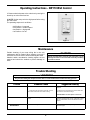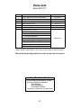
1
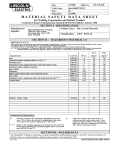
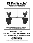
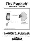
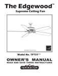
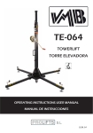
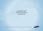
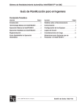
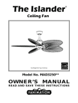
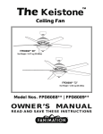
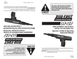
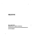
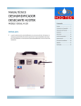
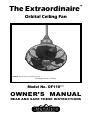
™ The Extraordinaire Orbital Ceiling Fan WARNING: Support Directly From Building Structure Net Weight 14.5 lbs. or 6.59 kg. Model No. OF110** OWNER’S MANUAL READ AND SAVE THESE INSTRUCTIONS Important Safety Instructions WARNING: To avoid fire, shock and serious personal injury, follow these instructions. 1. Read your owner’s manual and safety information before installing your new fan. Review the accompanying assembly diagrams. 2. Before servicing or cleaning unit, switch power off at service panel and lock service panel disconnecting means to prevent power from being switched on accidentally. When the service disconnecting means cannot be locked, securely fasten a warning device, such as a tag, to the service panel. 3. Be careful of the fan and blades when cleaning, painting, or working near the fan. Always turn off the power to the ceiling fan before servicing. 4. Do not insert anything into the fan blades while the fan is operating. 5. Do not operate reversing switch until fan blades have come to a complete stop. Additional Safety Instructions 1. To avoid possible shock, be sure electricity is turned off at the fuse box before wiring, and do not operate fan without blades. 2. All wiring and installation procedures must satisfy National Electrical Codes (ANSI/ NFPA 70-1999). Use the National Electrical Code if Local Codes do not exist. The ceiling fan must be grounded as a precaution against possible electrical shock. Electrical installation should be made or approved by a licensed electrician. 3. The fan base must be securely mounted and capable of reliably supporting at least 50 lbs. Outlet boxes are not acceptable for fan support. See page 4 of owner’s manual for support requirements. Consult a qualified electrician if in doubt. 4. CAUTION: To reduce the risk of personal injury, mount the fan base to a ceiling joist or structural member using the hardware provided with your fan. WARNING: Support Directly from Building Structure. 5. The fan must be mounted with the fan blades at least 7 feet from the floor to prevent accidental contact with the fan blades. 6. Follow the recommended instructions for the proper method of wiring your ceiling fan. If you do not have adequate electrical knowledge or experience, have your fan installed by a licensed electrician. 7. Suitable for use with solid-state speed controls. . WARNING: To reduce the risk of fire or electric shock, this fan should only be used with Fan Speed Control Part No. VR902F, manufactured by JOYKIM SCIENCE & TECH. CO., LTD. WARNING: TO REDUCE THE RISK OF SHOCK, THIS FAN MUST BE INSTALLED WITH AN ISOLATING WALL CONTROL/SWITCH. WARNING: This product is designed to use only those parts supplied with this product and/or accessories designated specifically for use with this product. Using parts and/or accessories not designated for use with this product could result in personal injury or property damage. WARNING: To reduce the risk of personal injury, do not bend the blade bracket (flange or blade holder) when installing the brackets, balancing the blades, or cleaning the fan. Do not insert foreign objects in between rotating fan blades. WARNING: All set screws must be checked and retightened where necessary before installation. WARNING: (a) A lubricant should not be used on the single mounting screw; and (b) The pilot hole should be drilled no larger than the minor diameter of the mounting screw threads, and at least 38mm (1½ inches) of the threaded part of the mounting screw should be secured into a structural wood joist to provide secure mounting. LIMITED LIFETIME WARRANTY Extends to the original purchaser of a Fanimation Fan 1. LIMITED LIFETIME MOTOR WARRANTY - If any part of your fan motor fails, due to a defect in materials or workmanship during the lifetime of the original purchaser, Fanimation will provide the replacement part free of charge, when the defective fan is returned to our national service center. Proof of purchase is required. Customer shall be responsible for all costs incurred in the removal or reinstallation and shipping of the product for repairs or replacement. 2. ONE YEAR MOTOR LABOR WARRANTY - If your fan motor fails at any time within one year from the original purchase, due to defects in materials or workmanship, labor to repair the motor will be provided free of charge at our national service center. Purchaser will be responsible for labor charges after this one-year period. Customer shall be responsible for all costs incurred in the removal or reinstallation and shipping of the product for repairs or replacement. 3. If any other part of your fan fails at any time within one year after original purchase, due to a defect in materials or workmanship, we will repair, or replace, at our option, the defective part free of charge for parts and labor performed at our national service center. 4. Because of varying climate conditions, this warranty does not cover changes in the finish, including rusting, pitting, corroding, tarnishing, or peeling. 5. This warranty is void and does not apply to damage from improper installation, neglect, accident, misuse, exposure to extremes of heat or humidity, or as a result of any modification to the original product. 6. All costs of removal and reinstallation of the fan are the sole responsibility of the owner of the fan and not the store that sold the fan or Fanimation. 7. Fanimation reserves the right to modify or discontinue any product at any time and may substitute any part under this warranty. 8. Under no circumstances may a fan be returned without prior authorization from Fanimation. The receipt of purchase must accompany authorized returns and must be sent freight prepaid to Fanimation. The fan to be returned must be properly packed to avoid damage in transit; Fanimation will not be responsible for any damage resulting from improper packaging. 9. It is understood that any repair or replacement is the exclusive remedy available from Fanimation. There is no other expressed or implied warranty. Fanimation hereby disclaims any and all implied warranties, including, but not limited to those of merchantability and fitness for a particular purpose to the extent permitted by law. Some states do not allow limitations on implied warranties. Fanimation will not be liable for incidental, consequential, or special damages arising out of or in conjunction with product use or performance, except as may otherwise be accorded by law. This warranty gives you special legal rights and you may also have other rights that vary from state to state. 10. A certain amount of wobble is normal and should not be considered a problem or a defect. Table of Contents Unpacking Instructions . . . . . . . . . . . . . . . . . . . . . . . . . . . . . . . . . . . . . . . . . . . . . . . . . . . . . . . . . . . . . . . . . . 3 Electrical and Structural Requirements . . . . . . . . . . . . . . . . . . . . . . . . . . . . . . . . . . . . . . . . . . . . . . . . . . . . . 4 How to Assemble Your Ceiling Fan . . . . . . . . . . . . . . . . . . . . . . . . . . . . . . . . . . . . . . . . . . . . . . . . . . . . . . . . . 4 How to Hang Your Ceiling Fan. . . . . . . . . . . . . . . . . . . . . . . . . . . . . . . . . . . . . . . . . . . . . . . . . . . . . . . . . . . . . 5 How to Wire Your Ceiling Fan – Rotary Switch . . . . . . . . . . . . . . . . . . . . . . . . . . . . . . . . . . . . . . . . . . . . . . . 7 How to Wire Your Ceiling Fan – CW110 Wall Control . . . . . . . . . . . . . . . . . . . . . . . . . . . . . . . . . . . . . . . . . . 7 Installing the Canopy Housing . . . . . . . . . . . . . . . . . . . . . . . . . . . . . . . . . . . . . . . . . . . . . . . . . . . . . . . . . . . . 8 Operating Instructions – Rotary Switch . . . . . . . . . . . . . . . . . . . . . . . . . . . . . . . . . . . . . . . . . . . . . . . . . . . . . 8 Operating Instructions – CW110 Wall Control . . . . . . . . . . . . . . . . . . . . . . . . . . . . . . . . . . . . . . . . . . . . . . . . 9 Maintenance . . . . . . . . . . . . . . . . . . . . . . . . . . . . . . . . . . . . . . . . . . . . . . . . . . . . . . . . . . . . . . . . . . . . . . . . . . . 9 Trouble Shooting. . . . . . . . . . . . . . . . . . . . . . . . . . . . . . . . . . . . . . . . . . . . . . . . . . . . . . . . . . . . . . . . . . . . . . . . 9 Parts List . . . . . . . . . . . . . . . . . . . . . . . . . . . . . . . . . . . . . . . . . . . . . . . . . . . . . . . . . . . . . . . . . . . . . . . . . . . . . 10 Exploded-View Illustration . . . . . . . . . . . . . . . . . . . . . . . . . . . . . . . . . . . . . . . . . . . . . . . . . . . . . . . . . . . . . . . 11 This Manual is Designed to Make it as Easy as Possible for You to Assemble, Install, Operate, and Maintain Your Ceiling Fan Tools Needed for Assembly Materials Wiring outlet box and box connectors must be of type required by local code. The minimum wire would be a 3-conductor (2-wire with ground) of the following size: • One Phillips head screwdriver • 7⁄16˝ Socket head wrench • One stepladder • One wire stripper • One ¼˝ blade screwdriver WARNING Before assembling your ceiling fan, refer to section on proper method of wiring your fan (page 4). If you feel you do not have enough wiring knowledge or experience, have your fan installed by a licensed electrician. Installed Wire Length Wire Size A.W.G. Up to 50 ft. 50 - 100 ft. 14 12 NOTE: Place the parts from the loose parts bags in a small container to keep them from being lost. If any parts are missing, contact your local retailer. Unpacking Instructions For your convenience, check-off each step. As each step is completed, place a check mark. This will ensure that all steps have been completed and will be helpful in finding your place should you be interrupted. Check to see that you have received the following parts: WARNING • Ceiling Fan assembly • Downrod assembly • Ceiling Canopy • Hanger Bracket assembly • Motor Coupling Cover • CW110 Wall Control • Hardware bag: – Four wire connectors – 7/16˝ wrench – ˝ x 5˝ lag bolt with Flat Washer – Phillips screwdriver, 1½˝ • Support Cable bag: – Ceiling Support Cable – Cable Clamp – ˝ x 2˝ lag bolt – ˝ flat washer Do not install or use fan if any part is damaged or missing. This product is designed to use only those parts supplied with this product and/or any accessories designated specifically for use with this product by Fanimation. Substitution of parts or accessories not designated for use with this product by Fanimation could result in personal injury or property damage. Contact your retail store for missing or damaged parts. NOTE: If you are uncertain of part description, refer to exploded view illustration. (Figure 1, page 11) Motor Coupling Cover Hanger Bracket Assembly Downrod Assembly CW110 Wall Control Hardware Bag Ceiling Canopy Ceiling Fan Assembly NOTE: The illustration shown is not to scale or its actual configuration may vary. Wires partially removed for clarity. 3 Electrical and Structural Requirements Your new ceiling fan will require a grounded electrical supply line of 120 volts AC, 60 Hz, 15 amp circuit. The outlet box must be securely anchored and capable of withstanding a load of at least 50 lbs. Figure 1 depicts different structural configurations that may be used for mounting the outlet box. Ceiling WARNING Turning off wall switch is not sufficient. To avoid possible electrical shock, be sure electricity is turned off at the main fuse box before wiring. All wiring must be in accordance with National and Local codes and the ceiling fan must be properly grounded as a precaution against possible electrical shock. Ceiling Joists WARNING 2˝ x 4˝ Outlet Box To avoid fire or shock, follow all wiring instructions carefully. Any electrical work not described in these instructions should be done or approved by a licensed electrician. Figure 1 How to Assemble Your Ceiling Fan 1. To prevent damage to housing and/or blade, leave the Ceiling Fan Assembly in its original packing during installation of down rod, motor coupling cover and ceiling canopy. Line up the holes for clevis pin installation NOTE: Do not set Ceiling Fan Assembly on floor or hard surface. 2. Prior to assembly, set aside and save the hardware bag(s) packed in the packing. NOTE: If using a downrod other than what is supplied with the fan, you must remove rubber sleeve from 6˝ downrod and put on new downrod. Figure 1 3. The fan comes with black, white, green 80˝ wires and support cable. Separate and untwist the wires. Route the wires and support cable through the downrod with rubber sleeve. 4. Be sure to line up the holes while pushing the downrod with rubber sleeve into the downrod support prior to installing clevis pin and hairpin clip. (Figure 1 & Figure 2) Clevis Pin Hairpin Clip WARNING It is critical that the clevis pin in the downrod support is properly installed. Failure to verify that the pin and hairpin clip are properly installed could result in the fan falling. Figure 2 4 How to Assemble Your Ceiling Fan (cont’d) 5. Disassembly the hanger bracket and ceiling canopy. (Figure 3) 6. Slide the motor coupling cover down until it touches the top of the motor and assemble ceiling canopy as shown. (Figure 4) 7. Before installing fan, measure up approximately 6-9 inches above top of downrod. Cut off excess wire and strip back insulation ½ ” from each end of wire. Figure 3 8. You have now completed the assembly of your new ceiling fan. You can now proceed with the hanging and the electrical wiring of your fan. Motor Coupling Cover Ceiling Canopy Figure 4 How to Hang Your Ceiling Fan ▲WARNING Ceiling To avoid possible electrical shock, be sure electricity is turned off at the main fuse box before hanging. NOTE: If you are not sure if the outlet box is grounded, contact a licensed electrician for advice, as it must be grounded for safe operation. 2 ft min. from staircase or wall WARNING: Do NOT Mount Fan On Wall Or Floor! ▲WARNING The fan must be hung with at least 7´ of clearance from floor to blade and MUST ONLY be hung in a vertical downward position from ceiling. (Figure 1) No less than 7 ft Floor Figure 1 5 How to Hang Your Ceiling Fan (cont’d) CAUTION Wood Member (2” x 4” Approx.) Ceiling Joist To Reduce the Risk of Personal Injury, this Product Must be Secured as Described in the Manual. 1. Attaching Ceiling Support Cable (Figure 2): Drill ¼˝ pilot hole through into the ceiling joist or structural member. Securely attach the ceiling support cable with 3⁄8˝ x 2˝ lag bolt and flat washer. NOTE: Ceiling support cable must be directly secured to ceiling joist or structural member between flat washer and junction box with 2˝ lag bolt (Figure 2). Ceiling Junction Box Hanger Bracket Ceiling Support Cable 2. Hanger Bracket Attachment (Figure 2): Drill ¼˝ pilot hole through the center of the junction box, into the ceiling joist or structural member. Attach hanger bracket to the ceiling structure using 3⁄8˝ x 5˝ lag bolt and flat washer. Figure 2 3. Assemble and secure the assembled fan with hexhead bolt, two lockwashers, nylon locknut and clevis pin. (Figure 3) Downrod (Assembled Fan) WARNING Figure 3 It is critical that the clevis pin and lock nut in the hanger bracket/downrod area is properly installed. Failure to verify that the nut and hairpin clip are properly installed could result in the fan falling. Loosen Nuts on both sides of the Hanger Bracket INSTALLATION NOTE The hanger bracket angle adjustment MUST ONLY be used to orientate the downrod in a vertical downward position. Sloped Ceiling 4. (Optional) Sloped Ceiling Installation (Figure 4): Loosen two nuts located on both sides of the hanger bracket to orientate the downrod in the vertical position. Figure 4 5. Make sure the electrical supply wires, including the hanger bracket grounding wire and safety cable are pulled through the downrod, between the hanger bracket and the junction box so that electrical connections can be made later. 6. Attach the safety cable to ceiling support cable. Slide cable clamp onto safety cable (from fan). Place the end of cable through the loop of ceiling support cable. Pull as much cable through loop as possible. Feed end of cable into clamp hole and firmly tighten screw (Figure 5). Cut off excess safety cable. Attach Safety Cable to Ceiling Support Cable WARNING To avoid possible shock, do not pinch wires between the downrod and the hanger bracket. NOTE: Supply wires and fan wires omitted for clarity 6 Figure 5 How to Wire Your Ceiling Fan – Rotary Switch If you feel that you do not have enough electrical wiring knowledge or experience, have your fan installed by a licensed electrician. NOTE: If fan or supply wires are different colors than indicated, have this unit installed by a qualified electrician. WARNING 120 VAC Supply (User Supplied) To avoid possible electrical shock, be sure electricity is turned off at the main fuse box before wiring. NOTE: If you are not sure if the outlet box is grounded, contact a licensed electrician for advice, as it must be grounded for safe operation. White (Neutral) Black Wire (Hot) Green Wire (Ground) (To/From hanger bracket and fan) 1. Run the black, white and green wires through the wiring hole in the side of the hanger bracket to allow for electrical connections. 2. Connect the green grounding wire from the fan and hanger bracket to the grounding wire from the outlet box (this may be a bare wire or a wire with green insulation). Securely connect these wires with wire connector supplied with your fan. 3. Securely connect the white wire from the fan motor to the white supply (neutral) wire using wire connector supplied (Figure 1). Figure 1 4. Securely connect the black fan motor wire to the black supply wire using wire connector supplied (Figure 1). 5. After connections have been made, turn leads upward and carefully push leads into the outlet box, with the white and green leads to one side of the box and the black leads towards the other side. 6. The wires should be spread apart with the grounded conductor and the equipment-grounding conductor on one side of the outlet box and the ungrounded conductor on the other side of the outlet box. How to Wire Your Ceiling Fan – CW110 Wall Control If you feel that you do not have enough electrical wiring knowledge or experience, have your fan installed by a licensed electrician. WARNING 1. Installing Wall Control (Figures 1 & 2): • With electrical power still disconnected, remove the existing wall plate and switch. • Make wiring connections with wire nuts as shown in Figure 1. – One black wire from wall control unit to black (hot supply). – One black wire from wall control unit to black wire leading to ceiling outlet box. – One green wire from wall control unit to ground wire leading to ceiling outlet box. BLK-TO MOTOR Figure 1 7 WH-TO MOTOR BLK TO HOT GRN WH GRN from bracket BLK TO FAN GRN TO GROUND GRN from hanger ball To avoid possible electrical shock, be sure electricity is turned off at the main fuse box before wiring. NOTE: If you are not sure if the outlet box is grounded, contact a licensed electrician for advice, as it must be grounded for safe operation. BLK 120 VAC SUPPLY (User Supplied) How to Wire Your Ceiling Fan – CW110 Wall Control (cont’d) • Attach wall control unit to outlet box using the two 6-32 screws provided. • Attach wall plate to the switch control front using the two small screws provided. Ground Supply To Fan WARNING Check to see that all connections are tight, including ground, and that no bare wire is visible at the wire connectors, except for the ground wire. Do not operate fan until the blades are in place. Noise and fan damage could result. 3 2 1 OF F Figure 2 Installing the Canopy Housing NOTE: This step is applicable after the necessary wiring is completed. WARNING To avoid possible fire or shock, make sure that the electrical wires are completely inside the canopy housing and not pinched between the housing and the ceiling. 1. Securely attach the Canopy Housing to the Hanger Bracket using the two screws supplied with your fan (Figure 1) Figure 1 Operating Instructions – Rotary Switch WARNING Check to see that all connections are tight, including ground, and that no bare wire is visible at the wire connectors, except for the ground wire. Do not operate fan until the blades is in place. Noise and fan damage could result. 1. Select the desired airflow located on the fan motor assembly by rotating clockwise. (Figure 1) • 1st position – high fan speed • 2nd position – medium fan speed • 3rd position – low fan speed • 4th position – fan off Figure 1 8 Hot Supply Operating Instructions - CW110 Wall Control 1. Restore electrical power to the outlet box by turning the electricity on at the main fuse box. 2. NOTE: Set the rotary switch to High speed before using the wall control. The operating sequence is as follows: • 4th Position = low speed • 3rd Position = medium speed • 2nd Position = high speed • 1st Position = fan off Figure 1 Maintenance Periodic cleaning of your new ceiling fan is the only maintenance that is needed. When cleaning, use only a soft brush or lint free cloth to avoid scratching the finish. Abrasive and/or non-abrasive cleaning agents are not required and should be avoided to prevent damage to finish. CAUTION Do not use water when cleaning your ceiling fan. It could damage the motor or the finish and create the possibility of electrical shock. Trouble Shooting WARNING For your own safety turn off power at fuse box or circuit breaker before trouble shooting your fan. Trouble 1. FAN WILL NOT START Probable Cause Suggested Remedy 1. Fuse or circuit breaker blown. 1. Check main and branch circuit fuses or circuit breakers. 2. Loose power line connections to the fan, or loose switch wire connections in the switch housing. 2. Check line wire connections to fan and switch wire connections in the switch housings. CAUTION: Make sure main power is turned off ! 2. FAN SOUNDS NOISY 1. Motor noise caused by solid state variable speed control. 1. Some fan motors are sensitive to signals from solid-state variable speed controls. Solid-state controls are not recommended, choose an alternative control method. 3. FAN WOBBLES EXCESSIVELY 1. Clevis nut in hanger bracket/downrod is loose. 1. Tighten clevis nut securely in hanger bracket/ downrod support. 9 Parts List Model #OF110** Ref. # Description Part # 1 Hanger Bracket with mounting hardware AP1160BL 2 Downrod with Clevis Pin, Hairpin Clip & Rubber Sleeve ADR110** 3 Ceiling Canopy P1163** 4 Motor Coupling Cover AP1115** 5 Fan Motor Assembly AMA110** 6 Wall Control CW110 Hardware Bag Containing: 7/16” Wrench (2) ⅜” x 5” Lag Bolt with Flat Washer 1½” Phillips Screwdriver 7 Wire Connectors (4) HDWOF110** Support Cable Bag Containing: Ceiling Support Cable with Cable Clamp ⅜ ” x 2” Lag Bolt Flat Washer Insert FINISH CODES (Refer to fan model number located on downrod support) Before discarding packaging materials, be certain all parts have been removed How To Order Parts When ordering repair parts, always give the following information: • Part Number • Part Description • Fan Model Number Contact your retail store for repair parts. 10 The Extraordinaire™ Exploded-View 1 1 (ref) 2 3 4 6 5 7 NOTE: The illustration shown is not to scale or its actual configuration may vary. Wires partially removed for clarity. Figure 1 11 Copyright 2009 Fanimation 10983 Bennett Parkway Zionsville, IN 46077 Toll Free (888) 567-2055 FAX (866) 482-5215 Outside U.S. call (317) 733-4113 Visit Our Website @ www.fanimation.com 2009/08 ™ The Extraordinaire Ventilador orbital de techo ADVERTENCIA: monte directamente en la estructura del edificio Peso neto 6,59 kg (14,5 lb) Modelo N.º OF110** MANUAL DEL PROPIETARIO LEA Y GUARDE ESTAS INSTRUCCIONES Instrucciones importantes de seguridad ADVERTENCIA: siga estas instrucciones para prevenir incendios, descargas eléctricas y lesiones personales graves. 1. Lea el manual del propietario y la información de seguridad antes de instalar su nuevo ventilador. Observe los diagramas de ensamblaje adjuntos. 2. Antes de llevar a cabo el mantenimiento o la limpieza de la unidad, desconecte la electricidad en el panel de servicio y bloquee los medios de desconexión del mismo para evitar que se active accidentalmente. Si no se pueden bloquear los medios de desconexión del servicio, coloque un dispositivo de advertencia, como una etiqueta, en el panel de servicio. 3. Tenga cuidado con la estructura y las aspas del ventilador cuando limpie, pinte o trabaje cerca del mismo. Desconecte siempre la electricidad del ventilador de techo antes de llevar a cabo el mantenimiento. 4. No coloque ningún elemento en las aspas del ventilador cuando éste se encuentre en funcionamiento. Instrucciones de seguridad adicionales 1. Para evitar posibles descargas eléctricas, asegúrese de que la electricidad esté desconectada de la caja de fusibles antes de realizar la instalación eléctrica, y no haga funcionar el ventilador sin las aspas. 2. Todos los procedimientos de conexión eléctrica e instalación deben cumplir con los Códigos Eléctricos Nacionales (ANSI/NFPA 70-1999). Utilice el Código Eléctrico Nacional si no existen Códigos Locales. El ventilador de techo debe estar conectado a tierra a fin de prevenir posibles descargas eléctricas. La instalación eléctrica debe ser llevada a cabo o aprobada por un electricista autorizado. 3. Se debe fijar bien la base del ventilador; ésta debe ser capaz de soportar sin problemas al menos 22,7 kg (50 lb). No se pueden utilizar cajas de distribución eléctrica como soporte del ventilador. Consulte la página 16 del manual del propietario para ver los requisitos de soporte. Consulte a un electricista calificado si tiene dudas. 4. PRECAUCIÓN: a fin de reducir el riesgo de lesiones personales, monte la base del ventilador en una viga de techo o miembro estructural con las herramientas suministradas con el ventilador. ADVERTENCIA: monte directamente en la estructura del edificio. 5. Las aspas del ventilador se deben instalar por lo menos a 2 m (7 pies) del suelo, a fin de evitar el contacto accidental con las mismas. 6. Siga las recomendaciones sobre el método correcto de instalación eléctrica de su ventilador de techo. Si no posee la experiencia o . los conocimientos eléctricos adecuados, contrate a un electricista autorizado para instalar el ventilador. 7. Apto para usar con controles de velocidad de estado sólido. ADVERTENCIA: a fin de reducir el riesgo de incendios o descargas eléctricas, este ventilador sólo debe utilizarse con la Pieza de Control de Velocidad para Ventiladores N.º VR902F, fabricada por JOYKIM SCIENCE & TECH. CO., LTD. ADVERTENCIA: PARA REDUCIR EL RIESGO DE DESCARGAS ELÉCTRICAS, ESTE VENTILADOR SE DEBE INSTALAR CON UN CONTROL/INTERRUPTOR DE PARED AISLADO. ADVERTENCIA: este producto está diseñado para ser utilizado sólo con las piezas suministradas o los accesorios indicados específicamente para el mismo. Si utiliza piezas o accesorios que no están indicados para su uso con este producto podría sufrir lesiones personales o dañar el ventilador. ADVERTENCIA: para reducir el riesgo de lesiones personales, no doble los soportes de aspas (borde o soporte de aspas) al instalar los soportes, balancear las aspas o limpiar el ventilador. No coloque objetos extraños entre las aspas del ventilador en funcionamiento. ADVERTENCIA: se deben revisar todos los tornillos y volver a ajustarlos según sea necesario antes de realizar la instalación. ADVERTENCIA: (a) No se debe utilizar lubricante en el tornillo de montaje; y b) el orificio guía no debe ser mayor que el diámetro más pequeño de la rosca del tornillo de montaje, y al menos 38 mm (1 ½ pulgadas) de la parte roscada del tornillo debe estar fijada en una viga de madera estructural, a fin de asegurar una instalación segura. GARANTÍA LIMITADA DE POR VIDA Se extiende al comprador original de un Ventilador Fanimation. 1. GARANTÍA LIMITADA DE POR VIDA DEL MOTOR: si se produce una falla en alguna de las partes del motor de su ventilador debido a un defecto en los materiales o en la fabricación durante el tiempo de vida del comprador original, Fanimation proporcionará la pieza de repuesto sin cargo una vez que se devuelva el ventilador defectuoso a nuestro centro de servicios nacional. Se requiere comprobante de venta. El cliente se hará responsable de todos los gastos de remoción o reinstalación y envío del producto para reparaciones o sustitución. 2. GARANTÍA DE MANO DE OBRA DEL MOTOR POR UN AÑO: si el motor de su ventilador falla antes de cumplirse un año a partir del momento de su compra original debido a defectos en los materiales o en la fabricación, se efectuará la reparación del mismo sin cargo en nuestro centro de servicios nacional. El comprador se hará responsable de los gastos de mano de obra luego del período de un año. El cliente se hará responsable de todos los gastos de remoción o reinstalación y envío del producto para reparaciones o sustitución. 3. Si otra pieza del ventilador fallara dentro del período de un año a partir de la fecha de compra original debido a un defecto en los materiales o en la fabricación, repararemos o sustituiremos, según creamos conveniente, la pieza defectuosa sin cargo alguno en nuestro centro de servicios nacional. 4. Debido a las diversas condiciones climáticas, esta garantía no cubre cambios en el acabado, incluidos oxidación, corrosión, falta de brillo o peladuras. 4. Debido a las diversas condiciones climáticas, esta garantía no cubre cambios en el acabado, incluidos oxidación, corrosión, falta de brillo o peladuras. 5. Esta garantía es nula y no se aplica a daños por instalación incorrecta, negligencia, accidentes, uso indebido, exposición al calor o a la humedad en exceso, o como resultado de cualquier modificación realizada al producto original. 6. Todos los gastos de remoción y reinstalación del ventilador son responsabilidad exclusiva del propietario, y no de la tienda que vendió el ventilador o de Fanimation. 7. Fanimation se reserva el derecho de modificar o discontinuar un producto en cualquier momento, o sustituir cualquier pieza según lo establecido por esta garantía. 8. Bajo ninguna circunstancia se podrá devolver un ventilador sin previa autorización por parte de Fanimation. Las devoluciones autorizadas deberán ir acompañadas del recibo de venta y deberán enviarse a Fanimation, previo pago del flete. El ventilador que se devuelve deberá estar embalado en forma adecuada a fin de evitar daños durante su transporte. Fanimation no se hará responsable de los daños que resulten del mal empaquetamiento del producto. 9. Se entiende que las reparaciones y las sustituciones son el único recurso disponible de Fanimation. No existe ninguna garantía expresa o implícita. Por la presente, Fanimation niega todas las garantías implícitas, que incluyen, entre otras, la comerciabilidad y la aptitud para determinado fin hasta donde la ley lo permita. Algunos estados no permiten limitaciones sobre las garantías implícitas. Fanimation no se hará responsable por daños accidentales, resultantes o especiales derivados del uso o el rendimiento del producto o en conjunción con éste, excepto en los casos en los que la ley así lo disponga. Esta garantía le otorga derechos legales especiales y es posible que también goce de otros derechos que pueden variar según el estado. Índice Instrucciones para el desempaque . . . . . . . . . . . . . . . . . . . . . . . . . . . .15 Requisitos eléctricos y estructurales. . . . . . . . . . . . . . . . . . . . . . . . . . .16 Cómo ensamblar el ventilador de techo . . . . . . . . . . . . . . . . . . . . . . . .16 Cómo colgar el ventilador de techo . . . . . . . . . . . . . . . . . . . . . . . . . . . .17 Cómo realizar la instalación eléctrica del ventilador de techo: interruptor giratorio . . . . . . . . . . . . . . . . . . . . . . . . . . . . . . . . . . . . . . . . .19 Cómo realizar la instalación eléctrica del ventilador de techo: control de pared CW110. . . . . . . . . . . . . . . . . . . . . . . . . . . . . . . . . . . . . .19 Instalación de la cubierta del capuchón . . . . . . . . . . . . . . . . . . . . . . . .20 Instrucciones de funcionamiento: interruptor giratorio. . . . . . . . . . . . 20 Instrucciones de funcionamiento: control de pared CW110 . . . . . . . . 21 Mantenimiento . . . . . . . . . . . . . . . . . . . . . . . . . . . . . . . . . . . . . . . . . . . . .21 Solución de problemas . . . . . . . . . . . . . . . . . . . . . . . . . . . . . . . . . . . . . .21 Lista de piezas . . . . . . . . . . . . . . . . . . . . . . . . . . . . . . . . . . . . . . . . . . . . .22 Ilustración del despiece. . . . . . . . . . . . . . . . . . . . . . . . . . . . . . . . . . . . . .23 Este manual está diseñado para facilitar, en la medida de lo posible, el ensamblaje, la instalación, el funcionamiento y el mantenimiento de su ventilador de techo Materiales Herramientas necesarias para el ensamblaje • Destornillador Phillips • Escalera de tijera • Destornillador de ¼˝ • Pelacables • Cuatro conectores de cables (incluidos) ▲ADVERTENCIA Antes de ensamblar el ventilador de techo, consulte la sección sobre el método correcto de instalación eléctrica del ventilador (página 16). Si siente que no posee la experiencia o los conocimientos eléctricos necesarios, contrate a un electricista autorizado para instalar el ventilador. La caja de distribución eléctrica y los conectores de la caja deben ser del tipo requerido por el código local. El cable más pequeño debe ser un cable de tres conductores (de dos conductores con conexión a tierra) del siguiente tamaño: tamaño del cable según el A.W.G. longitud del cable instalado (Calibre de Alambre Estadounidense) hasta 15,2 m (50 pies) 14 de 15,2 a 30,5 m (50 a 100 pies) 12 NOTA: coloque las piezas de las bolsas de piezas individuales en un contenedor pequeño para evitar que se extravíen. Si faltan piezas, póngase en contacto con su proveedor local. Instrucciones para el Desempaque Para su comodidad, marque cada uno de los pasos. A medida que completa cada paso, coloque una marca de verificación. Con esto se asegurará de completar todos los pasos y podrá saber desde dónde retomar si fuera interrumpido. Verifique que haya recibido las siguientes piezas: ▲ADVERTENCIA • unidad del ventilador de techo • unidad del barral • capuchón • unidad del soporte de suspensión • cubierta de unión del motor • control de pared CW110 • Bolsa de accesorios: – cuatro conectores de cables – llave de 7/16˝ – tornillo de cabeza cuadrada de 3/8˝ x 5˝ con arandela plana – destornillador Phillips de 1½˝ • Bolsa con cable de soporte: – cable de soporte para techo – abrazadera de cables – tornillo de cabeza cuadrada de 3/8˝ x 2˝ – arandela plana de 3/8˝ No instale ni utilice el ventilador si falta alguna pieza o si hay piezas dañadas. Este producto está diseñado para ser utilizado sólo con las piezas suministradas o los accesorios indicados por Fanimation específicamente para el mismo. La sustitución de piezas o accesorios que Fanimation no designó para usar con este producto podría ocasionar lesiones personales o daños en el ventilador. Póngase en contacto con su tienda si faltan piezas o hay piezas dañadas. NOTA: si no está seguro de la descripción de una pieza, consulte la ilustración del despiece. (Figura 1, página 23) cubierta de unión del motor unidad del soporte de suspensión unidad del barral control de pared CW110 Bolsa de accesorios capuchón unidad del ventilador de techo NOTA: la ilustración que se muestra no está hecha a escala y su configuración real puede variar. Los cables se dibujaron en forma parcial para mayor claridad. 15 Requisitos eléctricos y estructurales Su nuevo ventilador de techo requiere una línea de suministro eléctrico con conexión a tierra de 120 voltios de CA, 60 Hz, circuito de 15 amperios. La caja de distribución eléctrica debe estar bien asegurada y debe ser capaz de soportar una carga de, al menos, 22,7 kg (50 lb). La Figura 1 muestra diversas configuraciones estructurales que podrían utilizarse para montar la caja de distribución eléctrica. ▲ADVERTENCIA Techo Vigas del techo Apagar el interruptor de pared no es suficiente. Para evitar posibles descargas eléctricas, asegúrese de que la electricidad esté desconectada de la caja de fusibles principal antes de realizar la instalación eléctrica. Toda instalación eléctrica debe cumplir con los Códigos Nacionales y Locales y el ventilador de techo debe tener la conexión a tierra adecuada como forma de precaución ante posibles descargas eléctricas. ▲ADVERTENCIA Figura 1 5 x 10 cm (2˝ x 4˝) Caja de distribución eléctrica A fin de evitar incendios o descargas eléctricas, siga con cuidado todas las instrucciones de instalación eléctrica. Cualquier trabajo eléctrico que no se describa en estas instrucciones deberá ser realizado o aprobado por un electricista autorizado. Cómo ensamblar el ventilador de techo 1. Para prevenir daños en la cubierta o en las aspas, deje el ventilador de techo en su empaque original durante la instalación del barral, la cubierta de unión del motor y el capuchón. Alinee los orificios para colocar el pasador NOTA: no apoye la unidad del ventilador de techo en el suelo o en otra superficie dura. 2. Antes de realizar el ensamblaje, separe y guarde las bolsas de accesorios en el empaque. NOTA: si utilizará un barral distinto del que se suministra con el ventilador, deberá retirar la cubierta de goma del barral de 15 cm (6˝) y colocar el barral nuevo. Figura 1 3. El ventilador viene con cables de 2 m (80˝) de color negro, blanco y verde, y cables de soporte. Separe y desenrosque los cables. Pase los cables y el cable de soporte a través del barral con la cubierta de goma. 4. Asegúrese de alinear los orificios cuando introduzca el barral con la cubierta de goma en el soporte de barral antes de colocar el pasador y el pasador de horquilla. (Figura 1 y Figura 2) Pasador Pasador de horquilla ▲ADVERTENCIA Es fundamental que el pasador del soporte de barral esté instalado correctamente. Si el pasador y el pasador de horquilla no están correctamente colocados, el ventilador podría caerse. Figura 2 16 Cómo ensamblar el ventilador de techo (cont.) 5. Deslice la cubierta de unión del motor hacia abajo hasta que toque la parte superior del motor y ensamble el capuchón como se muestra. (Figura 3) 6. Antes de instalar el ventilador, mida aproximadamente de 15 a 23 cm (6 a 9 pulgadas) por encima de la parte superior del barral. Corte el excedente de cable y pele 1,2 cm (½˝) del aislamiento en cada extremo del cable. 7. De esta manera completó el ensamblaje de su nuevo ventilador de techo. Ahora puede continuar con las instrucciones para colgar el ventilador y realizar la instalación eléctrica. Cubierta de unión del motor Capuchón Figura 3 Cómo colgar el ventilador de techo ▲ADVERTENCIA Ceiling Techo Para evitar posibles descargas eléctricas, asegúrese de que la electricidad esté desconectada de la caja de fusibles principal antes de colgar el ventilador. NOTA: si no está seguro si la caja de distribución eléctrica tiene conexión a tierra, pida asesoramiento a un electricista autorizado, ya que la conexión a tierra es importante para un funcionamiento seguro. WARNING: NO ADVERTENCIA: Do NOT Mount Fanen Instale el ventilador Onpared Wall o Oren Floor! la el piso. ▲ADVERTENCIA Las aspas del ventilador deben estar suspendidas, al menos, a 2 m (7´) del piso y el ventilador SÓLO DEBE colgarse del techo, en posición vertical hacia abajo. (Figura 1) 2 ft min. 2 piesfrom (60 cm) staircase como mínimo or wall de la escalera o pared 2 m (7 Nopies) como less than mínimo 7 ft Piso Floor Figura 1 17 Cómo colgar el ventilador de techo (cont.) PRECAUCIÓN Miembro de madera (5 x 10 cm [2”x 4”] aprox.) A fin de reducir el riesgo de lesiones personales, este producto se debe asegurar como se describe en el manual. Viga del techo 1. Fijación del Cable de Soporte para Techo (Figura 2): Taladre un orificio guía de 0,6 cm (¼˝) a través de la viga de techo o el miembro estructural. Fije firmemente el cable de soporte para techo con el tornillo de cabeza cuadrada de 3⁄∕8˝ x 2˝ y la arandela plana. NOTA: el cable de soporte para techo se debe asegurar directamente a la viga de techo o miembro estructural, entre la arandela plana y la caja de conexiones, con un tornillo de cabeza cuadrada de 2˝ (Figura 2). Techo Caja de conexiones Soporte de suspensión Cable de soporte para techo 2. Sujeción del Soporte de Suspensión (Figura 2): taladre un orificio guía de 0,6 cm (¼˝) en el centro de la caja de conexiones y a través de la viga de techo o miembro estructural. Fije el soporte de suspensión a la estructura del techo con el tornillo de cabeza cuadrada de 3⁄∕8˝ x 5˝ y la arandela plana. Figura 2 3. Ensamble y asegure la unidad del ventilador con un perno de cabeza hexagonal, dos arandelas de seguridad, una tuerca de fijación de nylon y un pasador. (Figura 3) ▲ADVERTENCIA Barral (ventilador ensamblado) Es fundamental que el pasador y la tuerca de fijación del área del soporte de suspensión/barral estén instalados correctamente. Si la tuerca y el pasador de horquilla no están correctamente colocados, el ventilador podría caerse. Figura 3 Afloje las tuercas a ambos lados del soporte de suspensión NOTA DE INSTALACIÓN El ajuste del ángulo del soporte de suspensión SÓLO DEBE utilizarse como guía para colocar el barral en una posición vertical hacia abajo. 4. (Opcional) Instalación en techo inclinado (Figura 4): Afloje dos tuercas que se encuentran a ambos lados del soporte de suspensión para colocar el barral en posición vertical. Techo inclinado Figura 4 5. Asegúrese de que los cables de suministro eléctrico, incluido el cable de conexión a tierra del soporte de suspensión y el cable de seguridad, hayan atravesado el barral, entre el soporte de suspensión y la caja de conexiones, de modo que más tarde se pueda realizar la instalación eléctrica. 6. Fije el cable de seguridad al cable de soporte para techo. Deslice la abrazadera de cables por el cable de seguridad (del ventilador). Pase el extremo del cable a través del aro que forma el cable de soporte para techo. Tire lo más posible del cable a través del aro. Inserte el extremo del cable en el orificio de la abrazadera y ajuste firmemente el tornillo (Figura 5). Corte el exceso de cable de seguridad. NOTA: se omiten los cables de suministro y los cables del ventilador para mayor claridad. ▲ADVERTENCIA Para evitar una posible descarga eléctrica, no aprisione los cables entre el barral y el soporte de suspensión. 18 Fije el cable de seguridad al cable de soporte para techo Figura 5 Cómo realizar la instalación eléctrica del ventilador de techo: interruptor giratorio Si siente que no posee la experiencia o los conocimientos eléctricos necesarios, contrate a un electricista autorizado para instalar el ventilador. NOTA: si los cables de suministro o del ventilador son de colores diferentes que los indicados, contrate a un electricista calificado para que realice la instalación. ▲ADVERTENCIA Suministro de 120 V de CA (suministrado por el usuario) Para evitar posibles descargas eléctricas, asegúrese de que la electricidad esté desconectada de la caja de fusibles principal antes de realizar la instalación eléctrica. NOTA: si no está seguro si la caja de distribución eléctrica tiene conexión a tierra, pida asesoramiento a un electricista autorizado, ya que la conexión a tierra es importante para un funcionamiento seguro. Blanco (neutro) Cable negro (con carga) Cable verde (conexión a tierra) (de/al soporte de suspensión y ventilador) 1. Pase los cables negro, blanco y verde a través del orificio que se encuentra del lado del soporte de suspensión, de modo que se pueda llevar a cabo la instalación eléctrica. 2. Conecte el cable de conexión a tierra verde del ventilador y el soporte de suspensión al cable de conexión a tierra de la caja de distribución eléctrica (el mismo puede ser un cable desnudo o un cable con aislamiento de color verde). Conecte estos cables con el conector de cables suministrado con el ventilador. Figura 1 5. Luego de realizar las conexiones, doble los cables hacia arriba e insértelos con cuidado en la caja de distribución eléctrica, con los cables blanco y verde a un lado de la caja y los cables negros al otro lado. 3. Conecte el cable blanco del motor del ventilador al cable de suministro blanco (neutro) con el conector de cables suministrado (Figura 1). 6. Se deben separar los cables: el conductor con conexión a tierra y el conductor con conexión a tierra del equipo debe ir en un lado de la caja de distribución eléctrica y el conductor sin conexión a tierra debe ir del otro lado. 4. Conecte el cable negro del motor del ventilador al cable de suministro negro con el conector de cables suministrado (Figura 1). Cómo realizar la instalación eléctrica del ventilador de techo: control de pared CW110 Si siente que no posee la experiencia o los conocimientos eléctricos necesarios, contrate a un electricista autorizado para instalar el ventilador. ▲ADVERTENCIA Para evitar posibles descargas eléctricas, asegúrese de que la electricidad esté desconectada de la caja de fusibles principal antes de realizar la instalación eléctrica. NOTA: si no está seguro si la caja de distribución eléctrica tiene conexión a tierra, pida asesoramiento a un electricista autorizado, ya que la conexión a tierra es importante para un funcionamiento seguro. 19 Figura 1 VERDE del soporte VERDE de la semiesfera NEGRO A CABLE CON CARGA BLANCO A MOTOR VERDE A CABLE DE CONEXIÓN A TIERRA NEGRO A MOTOR 1. Instalación del control de pared (Figuras 1 y 2): • Con la electricidad todavía desconectada, retire la placa para pared y el interruptor existentes. • Realice las conexiones eléctricas con tuercas para terminales como se muestra en la Figura 1. – Un cable negro de la unidad de control de pared a cable negro (suministro con carga). – Un cable negro de la unidad de control de pared a cable negro que conecta con la caja de distribución eléctrica del techo. – Un cable verde de la unidad de control de pared a cable de conexión a tierra que conecta con la caja de distribución eléctrica del techo. VERDE NEGRO A VENTILADOR BLANCO NEGRO SUMINISTRO DE 120 V de CA (suministrado por el usuario) Cómo realizar la instalación eléctrica del ventilador de techo: control de pared CW110 (cont.) • Fije la unidad de control de pared a la caja de distribución eléctrica con los dos tornillos de 6-32 suministrados. • Fije la placa de pared al frente del control del interruptor con los dos tornillos pequeños suministrados. Tierra Suministro a ventilador ▲ADVERTENCIA 3 2 Verifique que todas las conexiones estén bien ajustadas, incluida la conexión a tierra, y que no haya ningún cable desnudo visible en los conectores de cables, a excepción del cable de conexión a tierra. No haga funcionar el ventilador hasta que las aspas estén colocadas. Podrían producirse ruidos y daños en el ventilador. 1 OF F Figura 2 Instalación de la cubierta del capuchón NOTA: este paso se debe realizar luego de completar la instalación eléctrica necesaria. ▲ADVERTENCIA Para evitar posibles incendios o descargas eléctricas, asegúrese de que los cables eléctricos se encuentran completamente adentro de la cubierta del capuchón y de que no están aprisionados entre la cubierta y el techo. 1. Ajuste bien la cubierta del capuchón al soporte de suspensión con los dos tornillos suministrados con el ventilador (Figura 1) Figura 1 Instrucciones de funcionamiento: interruptor giratorio ▲ADVERTENCIA Verifique que todas las conexiones estén bien ajustadas, incluida la conexión a tierra, y que no haya ningún cable desnudo visible en los conectores de cables, a excepción del cable de conexión a tierra. No haga funcionar el ventilador hasta que las aspas estén colocadas. Podrían producirse ruidos y daños en el ventilador. 1. Seleccione el flujo de aire deseado ubicado en la unidad del motor del ventilador girándolo en sentido horario. (Figura 1) • 1era posición – velocidad del ventilador alta • 2da posición – velocidad del ventilador media • 3era posición – velocidad del ventilador baja • 4ta posición – ventilador apagado Figura 1 20 Suministro con carga Instrucciones de funcionamiento: control de pared CW110 1. Vuelva a conectar la corriente eléctrica en la caja de distribución eléctrica mediante la conexión de la electricidad en la caja de fusibles principal. 2. NOTA: fije el interruptor giratorio en velocidad Alta antes de utilizar el control de pared. La secuencia de funcionamiento es la siguiente: • 4ta posición = low speed • 3era posición = velocidad media • 2da posición = velocidad alta • 1era posición = ventilador apagado apagado Figura 1 Mantenimiento El único mantenimiento necesario para el ventilador de techo es una limpieza periódica. Al llevar a cabo la limpieza, use sólo un cepillo suave o un paño sin pelusas, para evitar rayar el acabado. No se requieren agentes abrasivos ni no abrasivos de limpieza; los mismos deben evitarse para prevenir daños en el acabado. PRECAUCIÓN No utilice agua para limpiar el ventilador de techo. Podría dañar el motor o el acabado y ocasionar posibles descargas eléctricas. Solución de problemas ▲ADVERTENCIA Para su propia seguridad, desconecte la electricidad de la caja de fusibles o disyuntor antes de solucionar problemas en su ventilador. Problema 1. EL VENTILADOR NO ARRANCA Causa posible Solución sugerida 1. El fusible o el disyuntor están fundidos. 1. Controle los fusibles del circuito principal y derivado o los disyuntores. 2. Las conexiones eléctricas del ventilador o del interruptor en la caja del interruptor están flojas. 2. Controle las conexiones eléctricas del ventilador y del interruptor en las cajas de los interruptores. PRECAUCIÓN: ¡Asegúrese de que el suministro principal de electricidad esté desconectado! 2. EL VENTILADOR HACE RUIDO 1. Ruido del motor provocado por el control de velocidad de estado sólido variable. 1. Algunos motores de ventilador son sensibles a las señales de los controles de velocidad de estado sólido variables. Los controles de estado sólido no son recomendables. Escoja un método de control alternativo. 3. EL VENTILADOR OSCILA EN EXCESO 1. La tuerca en el soporte de suspensión/barral está floja. 1. Ajuste bien la tuerca del soporte de suspensión/ soporte del barral. 21 Lista de piezas Modelo N.º OF110** N.° de Ref. Descripción Pieza N.º 1 Soporte de suspensión con accesorios para montaje AP1160BL 2 Barral con pasador, pasador de horquilla y cubierta de goma ADR110** 3 Capuchón P1163** 4 Cubierta de unión del motor AP1115** 5 Unidad del motor del ventilador AMA110** 6 Control de pared CW110 Bolsa de accesorios que contiene: llave de 7/16˝ (2) tornillo de cabeza cuadrada de ⅜˝ x 5˝ con arandela plana HDWOF110 destornillador Phillips de 1½˝ 7 conectores de cables (4) Bolsa con cable de soporte que contiene: cable de soporte para techo con abrazadera de cable tornillo de cabeza cuadrada de ⅜˝ x 2˝ HWBSC240 arandela plana Inserte los CÓDIGOS DE ACABADO (Consulte el número de modelo del ventilador que se encuentra en el soporte de barral) Antes de desechar los materiales de embalaje, asegúrese de haber extraído todas las piezas Cómo hacer un pedido de piezas Al hacer un pedido de piezas de repuesto, proporcione siempre la siguiente información: • Número de pieza • Descripción de la pieza • Número de modelo del ventilador Contact your retail store for repair parts. 22 The Extraordinaire™ Despiece 1 1 (ref.) 2 3 4 6 5 7 NOTA: la ilustración que se muestra no está hecha a escala y su configuración real puede variar. Los cables se dibujaron en forma parcial para mayor claridad. Figura 1 23 Copyright 2009 Fanimation 10983 Bennett Parkway Zionsville, IN 46077 Llame Sin Cargo al (888) 567-2055 FAX (866) 482-5215 Desde fuera de los EE.UU. llame al (317) 733-4113 Visite nuestro sitio Web en www.fanimation.com 2009/11