1
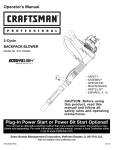
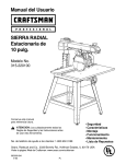
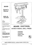
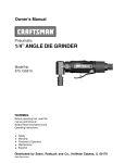
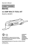
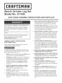
®
Grinq
21142q
:t
SAVE THESE ASSEMBLY
iNSTRUCTiONS
6,
AND PARTS LiST
KEEP VISITORS AND CHILDREN AWAY. DO NOT
permit people to be in the immediate work area,
especially when the electrical tool is operating,
ONE-YEAR
FULL WARRANTY
ON CRAFTSMAN
TOOL
7,
DO NOT FORCE THE TOOL to perform an operation for which it was not designed, it wiil do a safer
and higher quality job by only performing operations for which the tool was intended,
8,
WEAR PROPER CLOTHING.
ff this Craftsman tool fails due to a defect in material or
workmanship within one year from the date of purchase,
CALL 1-800-4-MY-HOME e_TO ARRANGE FOR FREE
REPAIR.
This warranty applies onIy while this tool is in the United
States.
This warranty gives you specific Iegal rights, and you may
aIso have other rights, which vary from state to state.
Sears, Roebuck and Co°, Dept° 817WA
Hoffrnan Estates, _L 60179
GENERAL SAFETY iNSTRUCTiONS
FOR POWER TOOL
Before using the Bench Grinder Leg Set, read and
understand the instruction Manual,
To avoid serious injury and damage to the tool, read
and follow all of the Safety and Operating instructions
before operating the Power Tool,
1,
READ the entire instruction Manual, LEARN how to
use the tool for its intended applications,
2,
GROUND ALL TOOLS, if the tool is supplied with a
3-prong plug, it must be plugged into a 3-contact
electrical receptacle, The 3rd prong is used to
ground the tool and provide protection against
accidental electric shock, DO NOT remove the
3rd prong,
3,
4,
5,
AVOID A DANGEROUS WORKING ENVIRONMENT. DO NOT use ebctdcal tools in a damp
environment or expose them to rain,
DO NOT use electrical tools in the presence of
flammable liquids or gasses,
ALWAYS keep the work area dean, well lit, and
organized, DO NOT work in an environment with
floor surfaces that are slippery from debris, grease,
and wax,
DO NOT wear loose
clothing, gloves, neckties, or jewelry, These items
can get caught in the machine during operations
and puil the operator into the moving parts, The
user must wear a protective cover on their hair, if
the hair is long, to prevent it from contacting any
moving parts,
9,
ALWAYS WEAR EYE PROTECTION, Any power
tool can throw debris into the eyes during operations, which could cause severe and permanent
eye damage, ALWAYS wear Safety Goggbs (that
comply with ANSI standard Z87,1) when operating
power tools, Safety Goggles are available at Sears
Retail Stores,
10, WEAR A DUST MASK TO PREVENT INHALING
DANGEROUS DUST OR PARTICLES,
11, ALWAYS UNPLUG THE TOOL FROM THE ELECTRICAL RECEPTACLE when making adjustments,
changing parts or performing any maintenance,
12, KEEP PROTECTIVE GUARDS IN PLACE AND IN
WORKING ORDER,
13, AVOID ACCIDENTAL STARTING, Make sure
that the power switch is in the "OFF" position
before plugging in the power cord to the electrical
receptacle,
14, REMOVE ALL MAINTENANCE
TOOLS from the
immediate area prior to turning "ON" the Bench
Grinder,
15, USE ONLY RECOMMENDED
ACCESSORIES,
Use of incorrect or improper accessories could
cause serious injury to the operator and cause
damage to the tool, if in doubt, check the instruction manual that comes with that particular accessory,
16,NEVERLEAVE
A RUNNING TOOL UNATTENDED,
23, DO NOT OPERATE TOOL IF UNDER THE
INFLUENCE OF DRUGS OR ALCOHOL,
Turn the power switch to the "OFF" position, DO
NOT leave the tool until it has come to a complete
stop,
24, SECURE ALL WORK, When it is possible, use
clamps or jigs to secure the workpiece, This is
safer than attempting to hold the workpiece with
your hands,
17, DO NOT STAND ON A TOOL, Serious injury
could result if the tool tips over or you accidentally
contact the took
18, DO NOT store anything above or near the tool where
anyone might try to stand on the tool to reach it,
19, MAINTAIN YOUR BALANCE.
SAVE THESE
iNSTRUCTiONS.
DO NOT extend
yourself over the tool, Wear oil resistant rubber°
soled shoes, Keep floor clear of debris, grease,
and wax,
20, MAINTAIN TOOLS WITH CARE, Always keep tools
clean and in good working order, Keep all blades
and tool bits sharp,
21, EACH AND EVERY TIME, CHECK FOR DAMAGED PARTS PRIOR TO USING THE TOOL,
Carefully check all guards to see that they operate
properly, are not damaged, and perform their
intended functions, Check for alignment, binding or
breaking of moving parts, A guard or other part that
is damaged should be immediately repaired
or replaced,
22, CHILDPROOF THE WORKSHOP AREA by
removing switch keys, unplugging tools from the
electrical receptacles, and using padlocks,
Figure
UNPACKUNG
AND CHECKUNG
This Bench Grinder Leg Set wiii require a minimal
amount of assembly, Use a rubber mallet or a hammer
with a wooden block for assembly,
Remove all of the parts from the shipping box,
Check and clean each part and lay them on a clean
work surface, Compare the items and quantities to
Figure 1-1,
CAUTION: if there is any missing or damaged parts,
do not attempt to assemble this Bench Grinder Leg Set,
To obtain missing or damaged parts, please call
1 °800°897°7709,
1-1
\
\
O:0
KEY
NO,
PART
NO,
DESCRmPTION
QTY, 1
1
OR93517
TRAY
2
STD52320
HEX HD SCR 5/16-18
3
STD551031
FLAT WASHER
4
STD551131
LOCK WASHER
5
6
STD541031
OR93518
HEX NUT 5/16-18
UPPER LEG
7
OR93519
LOWER LEG
8
OR93520
SHORT
9
OR93521
LONG HORIZONTAL
10
OR90394
FOOT
X 2" (not shown)
5/16" (not shown)
5/16" (not shown)
(not shown)
HORIZONTAL
2
4
2
2
4
4
SUPPORT
SUPPORT
2
2
4
7
CONTENTS
Figure
2-3
DO NOT ASSEMBLE the Bench Grinder Leg Set until
you have read and understand the entire instruction
Manual,
DO NOT ASSEMBLE the Bench Grinder Leg Set if
any parts are missing or damaged,
LEG SET ASSEMBLY
Figure
2-1
0
o
2,
Repeat Step 1 on the remaining Upper Legs,
3,
insert the 2 tabs on the end of the Lower Leg (7)
into the 2 slots in the end of the Upper Legs (refer
to Figure 2ol), Using a rubber mallet or a hammer
with a wooden block, tap the Lower leg until the
tabs are fully engaged into the Upper Leg,
4,
Repeat Step 3 on the remaining Lower Legs,
Figure
2-4
insert the 2 tabs on the end of the Upper Leg (6)
into the 2 shots in the Tray (1), See Figure 2ol,
Using a rubber mallet or a hammer with a wooden
Mock (Figure 2°2), tap the Upper ieg until the tabs
are fuliy engaged into the Tray, See Figure 2°3,
Figure
2-2
3
5,
insert the 4 square hobs on the Long Honzontal
Support (9) over the ears on the Lower Leg (see
Figure 2°4), Using a rubber mallet or a hammer
with a wooden Mock, tap the HonzontaH Support
downward until the square hobs bottom out on
the ears on the iower iegs,
6,
Repeat Step 5 on the Short HonzontaH Support (8)
See Figure 1ol,
7,
Assemble the plastic Foot (10) onto the end of each
Leg, See Figure 1ol,
GRINDER
TO LEG SET
HOW TO ORDER
To avoid injury, turn the grinder switch OFF and unplug
the Grinder from the power source before mounting
onto the leg set, See Figure 3-1,
1,
Position the Grinder (6) (not included) onto the Tray
(1) of the Leg Set,
2,
Align the mounting hobs in the base of the Grinder
with the hobs or slot in the Tray of the Leg Set,
3,
Secure the Grinder to the Leg Set with Hex Head
Screws (2), Fiat Washers (3), Lock Washers (4),
and Hex Nuts (5), Tighten all mounting hardware,
See Figure B,
Hex Head Screw (Qty, 2)
Fiat Washer (Qty, 4)
Lock Washer (Qty, 2)
Hex Nut (Qty, 2)
Figure
PARTS
Should a need exist for repair, parts or service for this
Bench Grinder Leg Set, simply contact any Sears Parts
Direct at 1-800-366-7278, For product information call
the Customer Helpline at 1-800-897-7709, Please
have your Model No,, Part No,, and Part Description
available,
When servicing, using only Craftsman replacement
parts, Use of any other parts may create a HAZARD
or cause product damage,
3-1
\
$
Sears, Roebuck
Ho#man Estates,/£
and Co.
60179 U.S.A.
Part No. 0R93516
®
para Rectificadora
"unto
odelo 211
GUARDE ESTAS JNSTRUCCJONES DE ENSAMBLAJE
6=
GARANTIA
COMPLETA
DE UN AltO
Si este producto queda averiado debido a defectos de
materiales o de elaboraci6n dentro de un a_o a partir de Ia
fecha de compra, DEVUELVALO A SU TENDA SEARS O
CRAFTSMAN MAS CERCANA y se la reemplazaremos
libre de costo=
NO FUERCE LA HERRAMIENTA a realizar operaciones
para las cuabs no fue dise[iada= Realizara una labor mb,s
segura y de mejor caJidad si se Ie utJliza para realizar
operaciones para las cuabs fue dise5ada=
8=
UTiLICE VEST_MENTA APROPJADA° NO vista ropa
holgada, guantes, corbatas ni articuios de joyerfa. Estos
art[cubs pueden quedar atrapados en Ia maquina
durante Ias operaciones y tirar deJ operado, atrayendolo
hacia Ias piezas en movimiento= El usuario debe IIevar
una cubierta protectiva sobre el cabello, si tiene cabeJIera
larga, para impedir el contacto con cualquier pieza en
movimiento=
g=
UT_UCE PROTECC_ON OCULAR SIEMPRE. Cualquier
herramienta mec_.nica puede arrojar escombros hacia Jos
ojos durante e! funcionamiento, pudiendo esto resuRar en
heridas ocuIares graves y permanentes= Utilice Gafas de
Protecci6n SlEMPRE (que cumplan con la normatlva
Z87.1 de ANSI) durante Ia operaci6n de herramientas
mecanicas. Las Gafas de Protecci6n estan disponibles
en las tiendas Sears de ventas al detak
Sears, Roebuck and Co., Dept. 817WA
Hoffrnan Estates, IL 60179
Antes de utiIizar el Conjunto de Patas para Rectificadora
Banco, lea y entienda el ManuaJ del Propietario=
de
Para evitar heridas graves y daSos a la herramienta, lea y
respecte todas Ias Instrucciones de Seguridad y
Funcionamiento antes de operar la Herramienta Mecb,nica=
1= LEA a consciencia el Manual del Propietario= APRENDA
c6mo hacer uso de esta herramienta para sus aplicaciones disehadas=
2=
3=
CONECTE TODAS LAS HERRAMIENTAS A TIERRA=
Si la herramienta se suministra con un enchufe de 3
machos, se le debe enchufar a un tomacorrientes que
disponga de 3 contactos el6ctricos= El tercer macho se
uti!iza para conectar Ia herramienta a tierra y ofrecer
protecci6n contra los choques electricos accidentales=
NO quite el tercer macho.
EVtTE UN ENTORNO LABORAL PELIGROSO° NO
utilice las herramientas el6ctricas en un entomo h0medo,
ni tampoco las exponga a Iluvia=
4=
NO utilice herramientas
infiamabbs presentes=
el6ctricas si hay gases o liquidos
5=
MANTENGA S[E[VIPRE su zona de trabajo limpia, bien
alumbrada y organizada. NO TRABAJE en un entorno
con superficies de piso resbalosas a consecuencia de los
escombros, la grasa y la cera=
MANTENGA ALEJADOS A LOS NINOS Y VISITANTES,
NO permita que haya personas en Ia zona inmediata de
trabajo, particuJarmente cuando la herramienta electrica
se encuentre en funcionamiento.
7=
Esta garant[a Ie otorga derechos legales especificos y
tambien podra tener otros derechos que pueden variar de
un estado al otro=
INSTRUCCIONES
GENERALES
DE
SEGURJDAD PARA LAS HERRA[VIIENTAS
MECANICAS
Y EL USTADO DE PJEZAS
10= UTILJCE UNA CARETA CONTRA EL POLVO PARA
EVITAR RESP_RAR POLVO O PART_CULAS PELF
GROSAS=
11= SJEMPRE DESENCHUFE LA HERRAMJENTA DEL
TOF,_ACORRIENTES cuando vaya a reaIizar ajustes,
cambiar piezas o realizar cualquier clase de mantenimiento=
12= MANTENGA LOS ESCUDOS DE PROTECCJON EN SU
SIT_O Y EN BUEN ESTADO DE FUNCIONAM_ENTO=
13= EVITE EL ARRANQUE ACCIDENTAL. Asegurese de
que el interruptor de potencia se encuentre en la posici6n
de "APAGADO" antes de enchufar el cord6n de potencia
en el tomacorrientes=
14= QU_TE TODAS LAS HERRAMIENTAS DE MANTENF
M_ENTO de la zona inmediata antes de encender Ja
Rectificadora de Banco=
15= SOLO UTILICE ACCESOR_OS RECOMENDADOS= Ei
uso de accesorios incorrectos o inapropiados puede
ocasionar heridas graves al operario y ocasionar daSo a
la herramienta= Si tiene dudas, consulte el manual de
instrucciones que se adjunta con el accesorio especifico=
16.JAMAS
DEJEUNANERRAI_vIIENTA
ENFUNC_ONAo
MIENTO
SiNATENDER.
Conmute
eIinterruptor
de
energfa
a Iaposici6n
deapagado.
NOabandone
Ia
herramienta
hastaqueestasehayadetenido
per
completo.
17.NOSEPARESOBRE
LANERRAMJENTA.
Pueden
producirse
hefidas
graves
si Iaherramienta
sevuelca
o si
ustedhacecontacto
conIaherramienta
accidentalmente.
18.NOAL_,_ACENE
nadaperencima
nicercadelamAquina
endonde
alguien
puedaintentar
pararse
enlaherramienta
paraalcanzarlo.
19.MANTENGA
SUEQUJLIBRIO.
NOseextienda
sobreIa
herramienta.
Hagausodezapatos
consueladecaucho
resistente
araceite.Mantenga
elpisolibredeescombros,
grasao cera.
20. MANTENGA
SUSHERRAMIENTAS
CUJDADOSAMENTE.
Mantenga
susherramientas
siempre
Iimpias
y
enbuenestado.
Mantenga
afiladas
todaslashojasy
brocas.
21. REVISE
SlNAYP_EZAS
DAf_ADAS
ANTES
DECADA
USODELAHERRAMIENTA.
Revise
todoslosprotectorescuidadosamente
paracomprobar
quefuncionan
correctamente
y quenoestanda_iados,
y querealizan
susfunciones
diseSadas
correctamente.
Revise
elalineamiento,
lafijaci6n
ola ruptura
delaspiezas
enmovimiento.Cuatquier
protector
u otrapiezaqueseencuentre
daRada
deberepararse
o reemplazarse
inmediatamente.
22. HAGASUTALLER
A PRUEBA
DENtNOS
quitando
las
Ilaves
delosinterruptores,
desenchufando
lasherramientasdelostomacorrientes,
y mediante
elusodecandados.
Figure
1-1
\
CEave de Pieza
\
Descripci6n
Cant.
1
0R93517
TRAY
2
STD52320
HEX HD SCR 5/16-18 x 2" (not shown)
1
2
3
STD551031
FLAT WASHER
4
4
STD551131
LOCK WASHER
5
6
STD541031
OR93518
HEX NUT5/16-18
UPPER LEG
7
OR93519
LOWER LEG
8
OR93520
SHORT
9
OR93521
LONG HORIZONTAL
10
OR90394
FOOT
5/16" (not shown)
5/16" (not shown)
(not shown)
HORIZONTAL
2
2
4
4
SUPPORT
SUPPORT
2
2
4
23. NOOPERE
LANERRAMIENTA
BAJOLA_NFLUENC_A
DELASDROGAS
ODELALCOHOL
24. AFIANCE
TODOELMATERIAL
Siempre
queresulte
posible,
utiliceabrazaderas
o ptantillas
paraasegurar
eI
material.
Estoofrecemayorseguridad
queintentar
sujetarelmaterial
consuspropias
manes.
GUARDE
ESTAS INSTRUCCIONES.
DESEMPAQUE
Y VERIFICACION
DE CONTENIDOS
El Conjunto de Patas para Rectificadora de Banco s61o necesitarS, una cantidad minima de ensamblaje. Se requiere una
Llave Aiustable (no incluida) para eI ensamblaje.
Quite todas las piezas de Ia caja de envio. Revise y Iimpie
cada una de las piezas, colocandolas sobre una superficie
de trabaio limpia. Compare los articulos y cantidades con el
listado de piezas y con la Figura 1-1.
PRECAUCION: Si faltan piezas, o si existen piezas dahadas,
no intente ensamblar este Conjunto de Patas para
Rectificadora de Banco. Para obtener piezas ausentes o
daRadas, tenga la bondad de Ilamar al 1-800-897-7709.
Figura
2-3
NO ENSAMBLE el Conjunto de Patas para Rectificador de
Banco sin haber le[do y entendido el Manual del Propietario
completamente.
NO ENSAMBLE el Conjunto de Patas de Rectificadora de
Banco si existen piezas dahadas o si fattan piezas.
ENSAMBLAJE
Figura
DE CONJUNTO
DE PATAS
2-1
0
o
2.
Repita el paso 1 para las otras patas superiores.
3.
Insierte las dos Ienguetas que se encuentran en ei
extreme de la pata inferior (7) en Ias dos ranuras de Ia
parte finat de las patas superiores (referirse a la figura 1).
Usando un martillo suave o bloque de madera, dar
golpecitos a Ia pata inferior hasta que las lenguetas
esten bien asentadas en la pata superior.
4.
Repita el paso 3 con las demas patas inferiores.
Figura
2-4
Inserte las 2 Ienguetas que se encuentran on eI extremo
de la pata superior (6) en las dos ranuras do la bandeja
(1). Vet figura 1. Usando un martillo suave o usar un
bloque de madera (figura 2), dar golpecitos on la pata
superior hasta que las Ienguetas queden asentadas en la
bandeja. Ver figura 3.
Figura
2-2
7
6
5.
Insierte en los 4 agujeros cuadrados que se encuentran
en el soporte largo horizontaI (9) sobre Ias orejas do la
pata inferior (ver figura 4). Usando un martiIIo o bloque
de madera dar golpecitos hacia abajo al soporte horizontal hasta que tos agujeros cuadrados se unan con las
orejas en las patas inferiores.
6.
Repita el paso 5 con el soporte corto horizontal (8).
7.
Coloque el pie plastico (10) en el extremo de cada pata.
RECTmFICADORA
DE PATAS
AL CONJUNTO
Para evitar heridas, conmute el interrupter de la rectificadora
a la posici6n de apagado (OFF) y desenchufe la Rectificadora
de Ia fuente de potencia antes de reatizar el montaje al conjunto de patas.
1.
Coloque la Rectificadora (6) (no incluida) sobre la
Bandeia (1) deI Conjunto de Patas.
2.
Aiinee los agujeros de montaje en Ia base de la
Rectificadora con los agujeros o la ranura en la Bandeja
del Conjunto de Patas.
3=
Afiance ta Rectificadora al Conjunto de Patas utilizando
los Tornillos de Cabeza Hexagona! (2), Arandelas Planas
(3), Arandetas de Cierre (4) y Tuercas Hexagonales (5).
Apriete toda Ia ferreteria de montaje. Ver Figura 3-1.
Tornillo de Cabeza Hexagonal (cant. 2)
Arandela Plana (cant. 4)
Arandela de Cierre (cant. 2)
Tuerca Hexagonal (cant. 2)
Figura
COMO ENCARGAR
PIEZAS
Si Ilegase a existir Ia necesidad de obtener piezas de
reparaci6n o servicio para este Conjunto de Patas para
Rectificadora de Banco, sencilIamente comun[quese con
cualquier Sears Parts Direct al 1-800-366-7278 (en EE.UU.).
Para informaci6n acerca deI producto, Ilame a la Linea de
Ayuda al Cliente al 1-800-697-7709. Tenga la bondad de
tener disponible su No. de Modelo, No. de Pieza y
Descripci6n de Pieza.
S61o utilice piezas de repuesto CRAFTSMAN cuando vaya a
realizar el servicio. El uso de piezas de cualquier otro tipo
puede crear un PEUGRO o daflar
el producto.
3-1
\
Sears, Roebuck
Ho#man Estates,//.
and Co.
G0179 U.S.A.
No. de Pieza OR93516