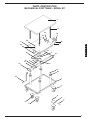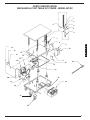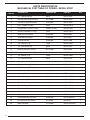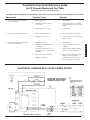
1
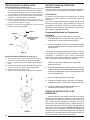
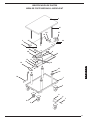
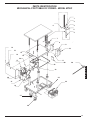
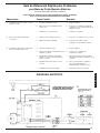
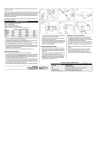
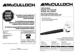
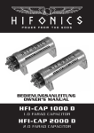
VESTIL MANUAFACTURING CORPORATION
2999 North Wayne St., Angola, IN 46703
Phone (260) 665-7586 • Fax (260) 665-1339
[email protected] • Website: www.vestil.com
Revised 04-04
21-126-103
A company dedicated to solving ergonomic and material
handling problems since 1955.
Ergonomic Solutions
OWNER'S
MANUAL
MECHANICAL POST TABLE • MODEL MT
Contents
Warning & Safety Instructions ......................... 1
Receiving Instructions ..................................... 1
Warranty .......................................................... 1
Ordering Replacement or Extra Parts ............. 2
Installation Instructions .................................... 2
Operating Instructions ..................................... 2
WARNINGS & SAFETY INSTRUCTIONS
Read owner's manual completely before operating unit!
• Not a personnel lift.
• Remove weight & disconnect power before working on unit.
• Use only maintenance parts supplied or approved by the
manufacturer.
• Never operate the lift unless you are watching it.
• Transport loads in the lowered position only.
• Don't continue to operate the control if unit is not moving.
• Consult factory before adding or performing any
modification to the original equipment.
RECEIVING INSTRUCTIONS
Every unit is thoroughly tested and inspected prior to
shipment. However, it is possible that the unit may incur
damage during transit. If you see damage when unloading
make a note of it on the SHIPPER RECEIVER.
Remove all packing and strapping material, inspect
for damage. IF DAMAGE IS EVIDENT, FILE A CLAIM WITH
THE CARRIER IMMEDIATLY! Also, check the unit size, type
of power unit, etc., to ensure the unit is correct for the intended
application.
Mechanical Post Table Parts List ............. 3-4
DC Powered Post Table Parts List ........... 5-6
Trouble Shooting Guide ............................... 7
Electrical Diagram ........................................ 7
Instructions for Battery-Powered Units ......... 8
instructions, or disassembly, repair or alteration by any
person prior to authorization from a factory representative.
ORDERING REPLACEMENT OR EXTRA PARTS
Our company takes pride in using the finest available
parts for our equipment. We are not responsible for
equipment failure resulting from the use of unapproved
replacement parts. To order replacement or extra parts for
your equipment contact Customer Service at the factory.
In any correspondence with the factory please include the
Serial Number which is inscribed on the nameplate of the
piece of equipment. Use only the part numbers provided
in this Owner's Manual. When ordering parts for AC power
units please indicate the motor phase and voltage that the
equipment is operating on.
WARRANTY
This product is warranted for 1 YEAR from date of
purchase to be free of manufacturing defects in material and
workmanship. The manufacturer's obligation hereunder is
limited to either providing replacement parts or repairing the
product, provided the product is sent prepaid back to the
factory.
This warranty does not cover normal wear of parts or
damage resulting from any of the following: negligent use or
misuse of the product, use or application contrary to installation
E
N
G
L
I
S
H
MECHANICAL POST TABLE
MODEL MT
1
E
S
P
A
N
O
L
INSTALLATION INSTRUCTIONS
OPERATING INSTRUCTIONS
INSTALLING CASTERS (fig. 1)
1.) Two 5" dai. swivel casters are installed on one end of
base frame (handle end of platform) and 5" dia. rigid
casters are installed on other end.
2.) Place the caster base plate into the caster pad bracket
(located on the bottom of frame).
3.) Insert 3/8" x 16 UNC x 5" long carriage bolt through
the square hole in the caster pad to hold the caster in
place.
4.) Place 3/8"-16 UNC lock nut on each bold and tighten
securely.
MANUAL HAND CRANK
Attach hand crank. Turn clockwise to raise unit and counter
clockwise to lower unit.
DC POWERED
Position of the deck is controlled by the hand-held pendent
control. The arrows display direction of travel of deck.
In order to operate the unit, pressure must be maintained in
the UP or DOWN position to raise or lower deck. On releasing
either button, the deck will remain at that particular position
until the button is depressed again.
RESPONSIBILITIES OF OWNERS/USERS
NUT
It is the responsibility of the owner/user for the following:
BOLT
CASTER PAD
BRACKET
1.) The lift must be inspected and maintained in accordance
with the guidelines in this manual.
2.) Any lift not in safe operating condition must be removed
from service until it is returned to proper operating condition.
CASTER
Figure 1
INSTALLING FLOOR LOCK - (fig. 2)
1.) Align mounting plate of floor lock with predrilled holes
on bottom of frame.
2.) Install floor lock with foot pedal bracket facing out.
3.) Insert four 3/8"-16 x 1" long hex head cap screws
through top of frame.
4.) Place four 3/8" - 16 lock nuts on each bolt and tighten
securely.
Unsafe condition may include, but is not limited to the following:
missing rollers, pins, or fasteners, any cracked or deformed
structural members, cut or frayed electric lines, and damaged
controls or safety devices.
All repairs and maintenance must be performed by qualified
personnel.
3.) Lift may only be used be used by authorized personnel.
All lift operators must have read and understood all
operating procedures and safety guidelines in this Owner's
Manual.
4.) Lift must never be overloaded.
5.) Operator must ensure that all safety features of the lift are
functioning properly before each use.
6.) Any modifications to the lift must be approved in writing by
the manufacturer.
Figure 2
2
PARTS IDENTIFICATION
MECHANICAL POST TABLE • MODEL MT
3
21
24
25
23
24
2
22
8
23
E
N
G
L
I
S
H
14
22
20
8
16
15
12
17
18
19
16
27
26
10
1
4
8
6
7
9
5
3
PARTS IDENTIFICATION
MECHANICAL POST TABLE • MODEL MT
DESCRIPTION
ENGINEER NO.
QTY.
1
Frame, Base Sub-Assy, MT
21-514-023/030
1
2
Deck, Center Plate (weldment), MT
21-513-009
1
3
Deck, Table Top, MT
21-013-024/027
1
4
Caster, Rigid, 5 x 2 poly on steel
16-132-022
2
5
Caster, Swivel, 5 x 2 poly on steel
16-132-021
2
6
Bracket, Caster Mount (bulldog)
16-132-076
4
7
Bolt, Carriage, 3/8 - 16 UNC x 5 Lg.
n/a
4
8
Nut, Hex, 3/8 - 16 UNC
n/a
10
9
Foot Lock
16-132-080
1
10
Crank Handle
14-025-001
1
11
Shaft, Slow Speed Gear, MT
14-026-004/006
1
12
Shaft, High Speed Gear, MT
14-026-007/009
1
13
Sprocket, #41 Chain (12 teeth)
21-042-007
1
14
Shaft collar, Split Shaft, with set screw 3/4"
n/a
1
15
Sprocket #41 Chain (24 teeth)
21-042-006
1
16
Chain, Roller
21-042-011
2
17
Spacer, High Speed Shaft
21-113-024
1
18
Gear, Bevel
21-042-005
1
19
Gear Ass'y, Bevel and Sprocket
21-542-001
1
20
Bracket, Sub-Ass'y, Tension Adjust, MT
21-516-001
1
21
Specialty Hardware, Lifting Thread
14-145-006
4
22
Washer, Lock, 3/8 Diameter
n/a
6
23
Washer, Flat, 7/16 Diamter
n/a
6
24
Bolt, HHCS, 2/8 - 16 UNC x 1-1/4 Lg.
n/a
6
25
Bracket, Removable Shaft Mtg.
21-016-026
2
26
Sprocket, Lifting, Post Crank
14-042-003
4
27
Spacer, Diameter 1-1/2 x 5/32 Wall x 5/8 Lg.
21-113-023
4
ITEM NO.
n/a - Not Available
4
PARTS IDENTIFICATION
MECHANICAL POST TABLE DC POWER • MODEL MT-DC
1
2
6
3
4
5
7
8
9
E
N
G
L
I
S
H
14
10
15
13
16
19
18
11
17
30
28
12
23
25
20
24
21
22
27
26
5
PARTS IDENTIFICATION
MECHANICAL POST TABLE DC POWER • MODEL MT-DC
DESCRIPTION
ENGINEER NO.
PART NO.
1
1/4 - 20 UNC Hex Nut
36102
MTDC-HXNT
1
2
Bearing, Roller (SWA-48 PMO)
20-110-008
MTDC-BRLR
2
3
Travel Bar Locator Weldment
21-516-004
MTDC-TBLW
1
4
5/16 - 18 UNC Lock Nut
37021
MTDC-LN516
2
5
Elevator Bolt 1/4 x 20 x 1-3/4 lg.
22805 (Fastenal)
MTDC-EVBLT
1
6
HHCS 1/4-20 UNC x 2-1/2 lg.
11013
MTDC-11013
1
7
Roller Arm Limit Switch
01-022-001
MTDC-RALS
2
8
Guest Battery Charger
21-034-001
MTDC-GBC
1
9
6 x 8 Control Box
01-029-007
MTDC-CB68
1
10
1/4 - 20 UNC x 1 lg.
11005
MTDC-11005
4
11
1/4 - 20 UNC Hex Nut
36102
MTDC-HXNT
4
12
Bushing Sleeve 3/4 x 3/4 lg.
01-111-009
MTDC-BS34
2
13
Bushing Sleeve 3/4 x 1/2 lg.
01-111-008
MTDC-BS12
1
14
1/4 - 20 UNC x 1 lg.
11005
MTDC-11005
2
15
1/4 - 20 UNC Hex Nut
36102
MTDC-HXNT
2
16
Safety Shroud, Chain Cover
21-024-020
MTDC-SSCC
1
17
Reducer, Hub city (SWA-48)
20-141-002
MTDC-HCR
1
18
DC Motor (1 hp) (PEL-400)
21-641-001
MTDC-DCMTR
1
19
Brkt. Weldment, Tension Adj.
21-516-005
MTDC-TAWB
1
20
1/2 x 13 UNC Hex Nut
36109
MTDC-36109
4
21
Brkt. Motor Base
21-016-064
MTDC-MTRBS
1
22
Chain RC-41 (MT-2436)
21-042-001
MTDC-CHAIN
1
23
ShaftGear
21-026-005
MTDC-SFTGR
1
24
Battery (w/case) (PEL-400)
21-139-002
MTDC-BAT
2
25
Rigid Caster 5" x 2"
16-132-022
MTDC-5X2PRC
2
26
Swivel Caster 5" x 2"
16-132-021
MTDC-5X2PSC
2
27
Floor Lock
16-132-080
MTDC-FL
1
28
Hand Control with Coil Cord
01-022-015
MTDC-HNDCNT
1
29
Circuit Breaker (not shown)
21-146-001
MTDC-CB
1
30
Motor Controller
21-156-003
MTDC-MTRCONT
1
ITEM NO.
6
QTY.
Troubleshooting Quick Reference Guide
for DC Powered Mechanical Post Table
(For further information contact the factory)
WARNING! BEFORE PERFORMING ANY MAINTENANCE WORK ALWAYS UNLOAD UNIT AND INSTALL MAINTENANCE SAFETY BAR(S)
Observation
Possible Cause
Remedy
1.)
a.
Battery voltage low.
a.
Charge battery.
b.
Bad wiring connection / broken
wire in circuit.
b.
Visually inspect wires, do continuity
checks with meter. Refer to electrical
diagram.
c.
Problem with motor / control.
c.
Consult factory.
a.
Chain / master link broken.
a.
Inspect and replace if necessary.
b.
Obstruction / jamed chain.
b.
Inspect chain, rollers, roller track and
pully assembly.
a.
Battery voltage low.
a.
Charge battery.
b.
Platform roller bearing obstructed
or is binding.
b.
Inspect roller track for interference
or damage.
c.
The "platfrom raised" limit switch
engaging too soon, or is bad (where
applicable).
c.
Adjust the limit switch pully spring's
tension: test switch with meter.
d.
Wire inside control cable broken.
d.
e.
Platform overloaded.
Rotate control around while pressing
button(s). If the unit operates
intermittently, change the control.
e.
Check load; reduce if neccessary.
2.)
3.)
Power unit does not run when hand
control is operated.
Motor hums, platform would not move.
Unit turns off before reaching the fully
raised or lowered height.
ELECTRICAL DIAGRAM WITH 24 VDC POWER OPTION
7
E
N
G
L
I
S
H
ADDITIONAL INSTRUCTIONS FOR BATTERY-POWERED UNITS
WARNING!
Working with or near lead acid batteries is dangerous. Batteries
contain sulfuric acid and produce explosive gases. A battery
explosion could result in loss of eyesight or serious burns.
Do not smoke or allow a spark or flame near batteries. Charge
batteries in locations which are clean, dry and well ventilated.
Do not lay tools or anything metallic on top of any battery. All
repairs to a battery must be made by experienced and qualified
personnel.
When working with batteries, remove personal items such as
rings, bracelets, necklaces, and watches. A battery can
produce enough voltage to weld jewelry to metal causing a
severe burn.
Always have plenty of fresh water and soap nearby in case
battery acid contacts skin, clothing, or eyes.
Operating the battery with a low battery voltage can cause
permature motor contact failure.
Do not expose the lift or charger to rain or adverse conditions.
Replace defective cords or wires immediately.
BATTERY CHARGER
OPERATING INSTRUCTIONS
Never operate the charger with either of the cables coiled.
Operating the unit wit the cord wrapped around itself could
cause the cord to overheat, melt, and cause a short-circuit or
file.
Plug the charger into a standard 115V receptacle. If an
extension cord must be used, keep it as short as possible.
Connection: the ribbed wire of the charger's output cord must
be connected to the batter's negative (-) terminal. The nonribbed wire must be connected to the batter's positive (+)
terminal. Reversing this polarity will blow the charger's ouput
fuse.
8
When properly connected, the charger will indicate the status
of charger output.
Flashing green, solid red LED - the charger is not seeing a good
connection to the battery, or the charger's ouput fuse has
blown.
Solid yellow and red LED's - the charger is providing a charging
current to the battery.
Solid green and red LED's - the charger is maintaining a fullycharged battery.
Caution: Remember to unplug the charger before moving the
equipment. Fauilure to do so could cause damage to cords,
receptacles and other equipment.
TROUBLESHOOTING
If the unti does not operate, check all the wiring connections to
make sure they're both machanically and electrically sound specifically at the battery, the motor, and at any location a wire
is connected to the chassis. Also make sure the quick-connect
plug on the end of the pendant control cord is plugged in
correctly.
A fully-charged lead acid battery is good condition at room
temperature should read 12.65 volts. At 11.9 volts it is
considered to be fully discharged an in need of charging. When
checking battery voltage, wait at leas 1/2 hour after the charger
as been turned off before checking the battery's voltage.
If the batteries don't seem to be taking a charger, check the
charger's 115V supply circuit, the charger's 10A output fuse,
and the charger's output with a voltmeter. If all check okay,
confirm the battery's state of charge using a hydrometer or a
voltmeter.
VESTIL MANUAFACTURING CORPORATION
2999 North Wayne St., Angola, IN 46703
Phone (260) 665-7586 • Fax (260) 665-1339
[email protected] • Website: www.vestil.com
Revisado 04-04
21-126-103
Una compañia dedicada a resolver problemas ergonómicos
y de manejo del material desde 1955.
Soluciones Ergonómicas
MANUAL DEL
PROPIETARIO
MESA DE POSTE MECÁNICA • MODELO MT
Contenido
Avisos e instrucciones de seguridad ....................... 9
Instrucciones de recibo ........................................... 9
Garantia .................................................................. 9
INstrucciones de instalación ................................. 10
Instrucciones de operación ................................... 10
ADVERTENCIAS E INSTRUCCIONES DE
SEGURIDAD
Lea el manual del propietario completamente antes de usar la unidad!
• No es un ascensor de personal.
• Nunca vaya debajo de las horquillas si la unidad tiene peso.
• Quite el peso y desconecte la electricidad antes de trabajar
en la unidad.
• Use solo partes de mantenimiento suministradas y
aprobadas por el fabricante.
• No cambie la válvula de relieve de presión.
• No agarre el cilindro hidráulico y a que podria romper el barril.
• Nunca opere el ascensor a no ser que lo este vigilando.
• No se hacerque si hay goteras-el aceite de alta presión pica
la piel con facilidad cuasando daños serios, gangrena y
hasta muerte.
• Carge la carga segura contra la mampara dentro de la
capacidad indicada.
• Transporte la carga solo en la posición baja.
• No continue apretando el control arriba (UP) si la unidad no
se está elevando.
• Alivie la presión del sistema apretando el control de bajada
(DOWN) después de que la unidad se haya parado.
• Consulte con el fabricante antes de añadir o hacer cualquier
modificación en el equipo originial.
• No use aceites de freno ni de gatos. Use solo aceite
hidráulica AW-32 o similar.
Pedidos de reemplazo o partes extra ................... 10
Lista de partes de la mesa de poste mecànica ..... 11
Mesa de poste eléctrica DC .................................. 12
Instrucciones de operación del cargador de batería .. 13
GARANTIA LIMITADA
Este producto está garantizado durante 365 DIAS
desde la fecha de compra de estar libre de defectos de
material y mano de obra. La obligación del fabricante está
limitada a reparar tales productos durante el periodo de
garantia, provisto que el producto se envie previo envio
flete pagado a la fábrica.
Esta garantia no cubre el gasto normal de partes
o daños que resulten de lo siguiente: uso negligente o mal
uso del producto, uso o aplicación contraria a las
instrucciones de instalación, o desensamble, reparaciones
o alteraciones por cualquier persona antes de la previa
autorización de un representante de la fábrica.
INSTRUCCIONES DE RECIBO
Cada unidad es inspeccionada a fondo y probada antes
del envio. Aún asi, es posible que la unidad se dañe durante el
envio. Si ve algún daño durante la descarga anótelo en el
RECIBO DE ENVIO.
Quite todo el material de empaquetado y las correas,
inspeccione por daños. Si hay daños evidentes, archive una
reclamación con el transportista immediatamente.
MESA DE POSTE MECÁNICA
MODELO MT
9
E
S
P
A
N
O
L
INSTRUCCIONES DE INSTALACIÓN
INSTRUCCIONES DE OPERACIÓN
INSTALACIÓN DE LAS RUEDAS (fig. 1)
1.) Dos ruedas locas de 12.7 cm de diam. se tienen que instalar
en cada extremo de la base del bastidor (en el extremo
de la manivela de la plataforma) y dos ruedas rígidas de
12.7 cm de diam. se tienen que instalar en el otro extremo.
2.) Ponga el plato de la base de la rueda en la almohadilla
de soporte. (Localizada debajo del bastidor).
3.) Inserte un tornillo largo de .95 cm-16 unc x 12.7 cm a
través del agujero cuadrado en la almohadilla de la rueda
para aguantar la rueda en su lugar.
4.) Ponga una tuerca de cierre de 0.95 cm x 16 unc en cada
tornillo y apriete con seguridad.
MANIVELA MANUAL
Agarre la manivela manual. Gire hacia la derocha para elevar
la unidad y hacia la izquierda para descender la unidad.
TUERCA
TORNILLO
ALMOHADILLA DE
SOPORTE DE LA
RUEDA
ELÉCTRICO DC
La posición de la plataforma es controlada por el control
manual. Las flechas indican la dirección de viaje de la
plataforma.
Para usar la unidad, se tiene que mantener presión en los
botones de arriba (UP) o abajo (DOWN) para elevar o
descender la plataforma. Cuando se suelte el botón, la
plataforma se mantendrá en esa posición particular hasta
que el botón se presione de nuevo.
Responsabilidades de los Propietarios/
Usuarious
El propietario/usuario es responsable de lo siguiente:
1.) El elevador debe de ser inspeccionado y reparado de
acuerdo con las instrucciones de este manual.
2.) Cualquier elevador que no funcione con seguridad debe
de ser removido del servicio hasta que vuelva a funcionar
correctamente.
RUEDA
Figura 1
INSTALACIÓN DEL FIJAMENTO AL PISO (fig. 2)
1.) Alinie el plato montante del fijamento del piso con las
perforaciones pretaladradas de debajo del bastidor.
2.) Instale el agarro del piso con el soporte del pedal hacia
fuera.
3.) Inserte cuatro tornillos largos de hex de 0.95 cm x 16 x
2.54 cm a través de la parte superior del bastidor.
4.) Ponga cuatro tuercas de cierre de
0.95 cm x 16 en cada tornillo y apriete con seguridad.
Condiciones de seguridad pueden incluir, pero no se limitan
a lo siguiente: aire o goteras hidráulicas excesivas, ruedas,
pasadores, o cerrojos en falta, partes estructurales
deformadas o rotas, lineas hidráulicas, eléctricas o de aire
rotas, y controles o partes de seguridad dañadas.
Todas las reparaciones deben de ser hechas por
personal calificado.
3.) El elevador solo debe ser usado por personal autorizado.
Todos los operarios del elevador deben de leer y entender
todos los procedimientos y guias de seguridad en este
manual del propietario.
4.) Nunca se debe sobrecargar el elevador.
5.) El operario se debe asegurar que todas las partes de
seguridad funcionan correctamente antes de cada uso.
6.) Cualquier modificación del elevador debe de ser
aprobada por escrito por el fabricante.
PEDIDO DE PARTES EXTRA O DE
REEMPLAZO
Figura 2
10
Nuestra compañia está orgullosa de utilizar en nuestro
equipo las partes disponibles más buenas. No nos hacemos
responsables si el equipo no funciona correctamente si se
han usado partes de reemplazo sin aprobar. Para pedir
partes extras o de reemplazo para su equipo contacte el
Servicio del Cliente de la fábrica. En toda la correspondencia
con la fábrica porfavor incluya el Número de Serie que está
inscrito en la placa del equipo. Solo use los números de
partes provistos en este Manual del Propietario. Cuando pida
partes para las unidades eléctricas AC porfavor indique la
fase y el voltaje del motor que el equipo utiliza.
IDENTIFICACIÓN DE PARTES
MESA DE POSTE MECÁNICA • MODELO MT
3
21
24
25
23
24
2
22
8
23
14
22
20
8
16
15
12
17
18
19
16
E
S
P
A
N
O
L
27
26
10
1
4
8
6
7
9
5
11
IDENTIFICACIÓN DE PARTES
MESA DE POSTE MECÁNICA
PARTIDA
NO. DE INGENIERO
CTD.
21-514-023/030
1
21-513-009
1
21-013-024/027
1
1
Frame, Base Sub-Assy, MT
2
Deck, Center Plate (weldment), MT
3
Deck, Table Top, MT
4
Rueda, rigida, acero de poly
16-132-022
2
5
Rueda, giratoria, acero de poly
16-132-021
2
6
Bracket, Caster Mount (bulldog)
16-132-076
4
7
Tornillo
n/a
4
8
Tuerca, hex
n/a
10
9
Freno de piso
16-132-080
1
10
Manivela de elevación
14-025-001
1
11
Eje, engranaje de baja velocidad
14-026-004/006
1
12
Eje, engranaje de alta velocidad
14-026-007/009
1
13
Sprocket, #41 Chain (12 teeth)
21-042-007
1
14
Collar del eje, eje con juego de tornillos
n/a
1
15
Sprocket #41 Chain (24 teeth)
21-042-006
1
16
Cadena, rodillo
21-042-011
2
17
Espacio, eje de alta velocidad
21-113-024
1
18
Engranaje, cónico
21-042-005
1
19
Ensamble de engranaje, cónico y de cadena
21-542-001
1
20
Soporte del sub-ensamble del ajuste de tensión
21-516-001
1
21
Specialty Hardware, Lifting Thread
14-145-006
4
22
Arandela, de cierre de 3/8 de diámetro
n/a
6
23
Arandela, plana
n/a
6
24
Tornillo
n/a
6
25
Soporte, eje movible
21-016-026
2
26
Manivela del poste de elevación de cadena
14-042-003
4
27
Espacio
21-113-023
4
n/a - Not Available
12
DESCRIPCIÓN
PARTS IDENTIFICATION
MECHANICAL POST TABLE DC POWER • MODEL MT-DC
1
2
6
3
4
5
7
8
9
14
10
15
13
16
19
18
11
30
17
28
12
E
S
P
A
N
O
L
23
25
20
24
21
22
27
26
13
IDENTIFICACIÓN DE PARTES
MESA DE POSTE ELÉCTRICA DC • MODELO MT
DESCRIPCIÓN
ENGINEER NO.
PART NO.
1
1/4 - 20 UNC tuerca hexagonal
36102
MTDC-HXNT
1
2
Cojinete de rodillos
20-110-008
MTDC-BRLR
2
3
Localizador de la soldadura de la barra de viaje
21-516-004
MTDC-TBLW
1
4
5/16 - 18 UNC Tuerca de cierre
37021
MTDC-LN516
2
5
Tornillo del ascensor 1/4 x 20 x 1-3/4 lg.
22805 (Fastenal)
MTDC-EVBLT
1
6
HHCS 1/4-20 UNC x 2-1/2 lg.
11013
MTDC-11013
1
7
Interruptor de limite del brazo del rodillo
01-022-001
MTDC-RALS
2
8
Cargador de batería de recambio
21-034-001
MTDC-GBC
1
9
6 x 8 Caja de control
01-029-007
MTDC-CB68
1
10
1/4 - 20 UNC x 1 lg.
11005
MTDC-11005
4
11
1/4 - 20 UNC Tuerca hexagonal
36102
MTDC-HXNT
4
12
Manga del buje 3/4 x 3/4 lg.
01-111-009
MTDC-BS34
2
13
Manga del buje 3/4 x 1/2 lg.
01-111-008
MTDC-BS12
1
14
1/4 - 20 UNC x 1 lg.
11005
MTDC-11005
2
15
1/4 - 20 UNC Tuerca hexagonal
36102
MTDC-HXNT
2
16
Mampara de protección, cubierta de la cadena
21-024-020
MTDC-SSCC
1
17
Reductor, tapa
20-141-002
MTDC-HCR
1
18
Motor DC (1 hp) (PEL-400)
21-641-001
MTDC-DCMTR
1
19
Soldadura del soporte, ajuste de tensión
21-516-005
MTDC-TAWB
1
20
1/2 x 13 UNC Tuerca hexagonal
36109
MTDC-36109
4
21
Soporte de la base del motor
21-016-064
MTDC-MTRBS
1
22
Cadena RC-41 (MT-2436)
21-042-001
MTDC-CHAIN
1
23
Eje
21-026-005
MTDC-SFTGR
1
24
Bateria (con caja)
21-139-002
MTDC-BAT
2
25
Rueda rigida 5" x 2"
16-132-022
MTDC-5X2PRC
2
26
Rueda giratoria 5" x 2"
16-132-021
MTDC-5X2PSC
2
27
Freno del piso
16-132-080
MTDC-FL
1
28
Hand Control with Coil Cord
01-022-015
MTDC-HNDCNT
1
29
Circuit Breaker (not shown)
21-146-001
MTDC-CB
1
30
Motor Controller
21-156-003
MTDC-MTRCONT
1
ITEM NO.
14
QTY.
Guia de Referencia Rápida para Problemas
para Mesa de Poste Mecánia Eléctrica
(Par más información contacte a la fábrica)
AVISO! ANTES DE TRABAJAR EN LA UNIDAD SIEMPRE DESCARGUE LA UNIDAD E
INSTALLE LAS BARRAS DE MANTENIMIENTO DE SEGURIDAD
Observación
Causa Posible
Remedio
1.)
a.
El voltaje de la batería es bajo.
a.
Cargue la batería.
b.
Male conexión de los alambres/circuito
eléctrico roto.
b.
Inspeccione los alambres visualmente,
compruebe con el contador. Refierase al
diagrama eléctrico.
c.
Problemas con el motor/control.
c.
Consulte con la fábrica.
a.
Cadena/el enlace principal está roto.
a.
Inspeccione y reemplace si es necesario.
b.
Obstrucción/cadena obstruida.
b.
Inspeccione la cadena, ruedas,
engranajes, y el ensamble de la polea.
a.
Voltaje de la batería es bajo.
a.
Cargue la batería.
b.
El perno de la rueda de la plataforma está
obstruido o doblado.
b.
Inspeccione el engranaje por
interferencias o daños.
c.
El interruptor de límite de "plataforma
elevada" se pone en marcha demasiado
rápido, o esta roto.
c.
Ajuste el muelle de la polea de tensión
del interruptor de limite: compruebe con un
contador.
d.
El alambre interior del cable de control
está roto.
d.
Gire el control mientras se aprieta el
botón. Si la unidad functiona
intermitentmente, cambie el control.
e.
La plataforma está sobreacargada.
e.
Check load; reduce if neccessary.
2.)
3.)
La unidad no funciona cuando el control
manual es usado.
El motor hace ruido, la plataforma
no se mueve.
La unidad se apaga antes de alcanzar la
posición elevada o de descenso.
E
S
P
A
N
O
L
DIAGRAMA ELÉCTRICO
15
INSTRUCCIONES DE USO DEL CARGADOR DE LA BATERIA
Carador de Bateria Estilo Banco
(Para models DC Equipados con nuestro cargador de bateria estilo banco)
AVISO!
El trabajar con o cerca de baterias de ácido es peligroso.
Las baterias continene ácido sulfurico y producen gases
explosivos. Una explosión de la baterias podria resultar en la
perdida de la vista o en quemaduras serias.
INSTRUCCIONES DE USO
Aunque usted no haya comprada el cargador de bateria
opcional, su nuevo Mesa de Poste Eléctrica DC tiene un
enchufe que conecta directamente al cargador de banco.
Contacte a su distribuidor si desea comprar un cargador de
bateria.
QUE HACER Y QUE NO HACER
NO deje el cargador conectado durante un tiempo indefinido.
No fume o permita que una chispa o una llama este cerca
de las baterias. Carge las baterias en lugares limpios, secos
y bien ventilados. No ponga herramientas o algo metálico
encima de la bateîa. Todas loas reparaciones de la bateria
deben de ser hechas por personal calificado y con experiencia.
Cuando se trabaje con baterias, quitese todos los articulos
personales como anillos, pulseras, collares y relojes. La
bateria puedde producir tal voltage que las joyas se adhieran
al metal causando quemaduras severas.
Siempre tenga abundante agua fresca y jobón cerca en
caso de que el ácido de la bateria torque la piel, ropa o los
ojos.
Si se opera la bateria con poco voltage podria causar que
el motor fallase prematuramente.
16
NO fume, encienda una llama o cause chispas cerca de la
bateria cuando se está cargado.
ASEGURESE de que las conexiones de la bateria estan
limpias.
NO exponga a la lluvia o a condiciones adversas.
REEMPLACE cordones defectivos y alambres imediatamente
PONGA el cargador como minimo a 24" por encima del piso
cuando se este cargando.
NO sobrecarge la bateria (solo en la posición manual).