1
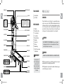
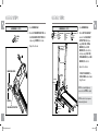
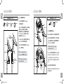
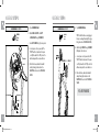
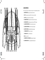
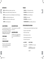
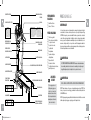
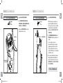
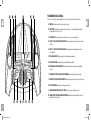
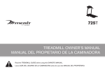
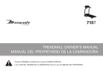
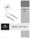
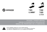
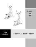
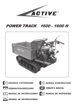
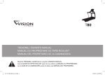
735T TREADMILL OWNER’S MANUAL MANUAL DEL PROPIETARIO DE LA CAMINADORA Read the treadmill guide before using this owner’s manual. Lea la GUÍA DEL USUARIO DE LA CAMINADORA antes de usar este MANUAL DEL PROPIETARIO. 735TSM-Eng-MSp-OM-rev1.4.indd 1 9/9/09 9:48 AM 3 24 ENGLISH Español ASSEMBLY WARNING There are several areas during the assembly process that special attention must be paid. It is very important to follow the assembly instructions correctly and to make sure all parts are firmly tightened. If the assembly instructions are not followed correctly, the treadmill could have parts that are not tightened and will seem loose and may cause irritating noises. To prevent damage to the treadmill, the assembly instructions must be reviewed and corrective actions should be taken. Before proceeding, find your treadmill’s serial number located near the on/off power switch and power cord and enter it in the space provided below. ENTER YOUR SERIAL NUMBER IN THE BOX BELOW: SERIAL NUMBER: MODEL NAME: MERIT 735T TREADMILL » Refer to the SERIAL NUMBER and MODEL NAME when calling for service. » Be sure to enter both the SERIAL NUMBER and MODEL NAME on your warranty card. 2 735TSM-Eng-MSp-OM-rev1.4.indd 2-3 3 9/9/09 9:48 AM WATER BOTTLE HOLDER READING RACK TOUCH PAD PANEL CONSOLE AVERTISSEMENT WARNING ATTACH SAFETY KEY CLIP TO CLOTHING BEFORE STARTING. TO AVOID INJURY, STAND ON THE SIDE RAILS BEFORE STARTING TREADMILL. READ AND FOLLOW ALL INSTRUCTIONS BEFORE OPERATING. KEEP CHILDREN AWAY FROM THIS EQUIPMENT. REMOVE SAFETY KEY WHEN NOT IN USE AND STORE OUT OF REACH OF CHILDREN. CONSULT A PHYSICIAN BEFORE USING THIS EQUIPMENT. STOP EXERCISING IF YOU FEEL PAIN, FAINT, DIZZY OR SHORT OF BREATH. FOR CONSUMER USE ONLY. ATTACHER LA PINCE DE LA CLÉ DE SÉCURITÉ AUX VÊTEMENTS AVANT DE COMMENCER. POUR ÉVITER TOUTES BLESSURES, SE TENIR SUR LES RIDELLES AVANT DE DÉMARRER LE TAPIS ROULANT. AVANT USAGE, LIRE LE GUIDE D’UTILISATEUR. NE PAS LAISSER CET ÉQUIPEMENT À LA PORTÉE DES ENFANTS. ENLEVER LA CLÉ DE SÉCURITÉ LORSQUE LE TAPIS ROULANT N’EST PAS UTILISÉ ET LA RANGER HORS DE LA PORTÉE DES ENFANTS. CONSULTER UN MÉDECIN AVANT D’UTILISER CET ÉQUIPEMENT. ARRÊTER D’UTILISER L’APPAREIL EN CAS DE DOULEUR, D’ÉVANOUISSEMENT, DE VERTIGE OU D’ESSOUFFLEMENT. POUR USAGE DOMESTIQUE UNIQUEMENT. GRIP PULSE HANDRAILS ON/OFF SWITCH MOTOR COVER FRAME EXTENSION TUBE CAUTION AVERTISSEMENT PRECAUCIÓN GARDER LES MAINS ET LES PIEDS LOIN DE CETTE REGION. MANTENGA LAS MANOS Y LOS PIES LEJOS DE ESTA AREA. CUSHIONING GARDER LES MAINS ET LES PIEDS LOIN DE CETTE RÉGION. 4 735TSM-Eng-MSp-OM-rev1.4.indd 4-5 RUNNING BELT / RUNNING DECK ROLLER END CAP SIDE RAIL CAUTION AVERTISSEMENT PRECAUCIÓN HOLD ONTO DECK WHEN LATCH IS RELEASED. SAFETY KEY PLACEMENT DECK LOCK PIN TRANSPORT WHEEL KEEP HANDS AND FEET AWAY FROM THIS AREA. SUJETE LA LLAVE DE SEGURIDAD A SU ROPA ANTES DE COMENZAR. PARA EVITAR ACCIDENTES PARESE EN LO RIELES ANTES DE COMENZAR. LEA CUIDADOSAMENTE EL MANUAL DE USUARIO Y CONSULTE A SU MEDICO ANTES DE COMENZAR. MANTENGA EL PRODUCTO FUERA DEL ALCANZE DE LOS MENORES. QUITE LA LLAVE DE SEGURIDAD CUANDO NO ESTE EN USO. CONSULTAR CON UN MEDICO ANTES DE USAR ESTE EQUIPO. SI SIENTE ALGUN DOLOR O FATIGA PARE DE INMEDIATO. ESTE EQUIPO ES SÓLO PARA EL USO DEL CONSUMIDOR. CONSOLE MAST POWER CORD SUJETE LA PLATAFORMA CUANDO VAYA BAJANDO. FF 5 mm Allen Wrench FF 4 mm T-Wrench PRECAUCIÓN HANDLEBARS CIRCUIT BREAKER TOOLS INCLUDED: REAR ROLLER ADJUSTMENT BOLTS PARTS INCLUDED: FF FF FF FF FF FF FF FF FF FF 1 Safety Key 2 Frame Extention Tubes 1 Console Assembly 2 Console Masts 1 Water Bottle Holder 2 Hand Grips 1 Deck Lock Pin 2 End Caps 4 Hardware Bags 1 Bottle of Silicone Lubricant (for 2 applications) NEED HELP? If you have questions or if there are any missing parts, contact Customer Tech Support. Contact information is located on the back panel of this manual. PRE ASSEMBLY UNPACKING Place the treadmill carton on a level flat surface. It is recommended that you place a protective covering on your floor. Take CAUTION when handling and transporting this unit. Never open box when it is on its side. Once the banding straps have been removed, do not lift or transport this unit unless it is fully assembled and in the upright folded position, with the lock latch secure. Unpack the unit where it will be used. Never grab hold of any portion of the incline frame and attempt to lift or move the treadmill. WARNING DO NOT ATTEMPT TO LIFT THE TREADMILL! Do not move or lift treadmill from packaging until specified to do so in the assembly instructions. You may remove the plastic wrap from console masts. WARNING FAILURE TO FOLLOW THESE INSTRUCTIONS COULD RESULT IN INJURY! NOTE: During each assembly step, ensure that ALL nuts and bolts are in place and partially threaded in before completely tightening any ONE bolt. NOTE: A light application of grease may aid in the installation of hardware. Any grease, such as lithium bike grease is recommended. 5 9/9/09 9:48 AM ASSEMBLY STEP 1 HARDWARE BAG 1 CONTENTS : SCREW (A) 15 mm Qty: 4 ASSEMBLY STEP 2 A Open hardware bag 1. B Slide the left frame extension tube onto the console mast support tube. Bolt in place using 2 SCREWS (A) on the side. HARDWARE BAG 2 CONTENTS : BOLT (B) 15 mm Qty: 8 SPRING WASHER (C) 15 mm Qty: 8 C Repeat on the other side. CONSOLE CABLE (THREAD THROUGH TOP OF CONSOLE MAST) RIGHT CONSOLE MAST FLAT WASHER (D) 15 mm Qty: 4 ARC WASHER (E) 17 mm Qty: 4 A Open hardware bag 2. B Slide the left console mast down onto the console mast support tube. Bolt in place using 2 bolts (b), 2 spring washers (c), and 2 flat washers (d) on the side. Then, bolt in place using 2 bolts (b), 2 spring washers (c), and 2 arc washers (e) on the front. C Repeat on the other side. FRAME EXTENSION TUBE CONSOLE MAST SUPPORT TUBE ARC WASHER (E) SPRING WASHER (C) On right console mast, the console cable must be threaded through the mast. BOLT (B) Note: Do not completely tighten any screws or bolts until step 4 is complete! Note: Be careful not to pinch any wires while assembling the masts. SCREWS (A) CONSOLE MAST SUPPORT TUBE FLAT WASHER (D) SPRING WASHER (C) BOLT (B) 6 735TSM-Eng-MSp-OM-rev1.4.indd 6-7 7 9/9/09 9:48 AM ASSEMBLY STEP 3 ASSEMBLY STEP 4 HARDWARE BAG 3 CONTENTS : BOLT (B) 15 mm Qty: 6 SPRING WASHER (C) 15 mm Qty: 4 FLAT WASHER (D) 15 mm Qty: 4 A Open hardware bag 3. B Insert left hand grip onto upright console mast. ARC WASHER (F) 18 mm Qty: 2 HARDWARE BAG 4 CONTENTS : C Attach the left hand grip to the console mast using 2 bolts (b), 2 spring Washers (c) and 2 flat washers (d) from the inside and 1 bolt (b) and 1 arc washer (f) from the front. CONSOLE CABLE (THREAD THROUGH HOLE IN RIGHT HAND GRIP) HAND GRIP FLAT WASHERS (D) BOLTS (B) Carefully thread the console cable through the hole in the right hand grip. E Attach the right hand grip as explained above in steps b–c. SPRING WASHERS (C) BOLTS (B) Note: Be careful not to pinch any wires while assembling the masts. ARC WASHERS (H) SCREWS (G) Open hardware bag 4. B Slide the console onto the hand grip posts. using 4 screws (g) and 4 arc washers (h) from the below the console. Note: Be careful not to pinch any wires while attaching the console. D Connect the console cables and carefully tuck wires in mast to avoid damage. Note: do not pinch console cable. Be sure the console cable prongs are aligned and the ends are tightly seated into each other. E Attach console cable cover. F Go back and completely tighten all bolts and screws from steps 1-4. CONSOLE CONSOLE CABLE CONSOLE CABLE COVER 735TSM-Eng-MSp-OM-rev1.4.indd 8-9 A C Attach the hand grip posts to the console UPRIGHT MAST 8 ARC WASHER (H) 12 mm Qty: 4 HAND GRIP POST Note: Do not completely tighten any screws or bolts until step 4 is complete! CONSOLE MAST ARC WASHERS (F) D SCREW (G) 10 mm Qty: 4 CONSOLE 9 9/9/09 9:48 AM ASSEMBLY STEP 5 ASSEMBLY STEP 6 HARDWARE BAG 5 CONTENTS : SCREW (I) 17 mm Qty: 2 A Open hardware bag 5. B Attach deck lock pin to the left console mast using 2 screws (I). HARDWARE BAG 6 CONTENTS : A Note: lock latch must be securely engaged before proceeding with assembly. (See page folding instructions in treadmill guide.) SCREW (J) 15mm Qty: 4 C Insert cup holder into right console pocket. D CUP HOLDER CONSOLE E Connect power cord to a power outlet. The on/off switch is located next to the power cord. Flip this switch to the ‘ON’ position. You will hear a beep and the console will turn on. Before the first use, lubricate the treadmill deck by following the instructions in the maintenance section in the treadmill guide. Open hardware bag 6. B Attach the right end cap using 2 SCREWS (j). Repeat on the other side. C Connect power cord to a power outlet. The SCREWS (J) on/off switch is located next to the power cord. Flip this switch to the ‘ON’ position. You will hear a beep and the console will turn on. END CAP D Before the first use, lubricate the treadmill deck by following the instructions in the maintenance section in the treadmill guide. YOU ARE FINISHED! LEFT CONSOLE MAST DECK LOCK PIN SCREWS (I) 10 735TSM-Eng-MSp-OM-rev1.4.indd 10-11 11 9/9/09 9:48 AM TREADMILL OPERATION This section explains how to use your treadmill’s console and programming. The BASIC OPERATION section in the treadmill guide has instructions for the following: • LOCATION OF THE TREADMILL • Using the SAFETY KEY • FOLDING the treadmill • MOVING the treadmill • LEVELING the treadmill • TENSIONING THE RUNNING BELT • CENTERING THE RUNNING BELT • Using the HEART RATE function 13 735TSM-Eng-MSp-OM-rev1.4.indd 12-13 9/9/09 9:48 AM L F I A J G CONSOLE OPERATION Note: There is a thin protective sheet of clear plastic on the overlay of the console that should be removed before use. A) Monitor display: Speed, time, pulse, distance, incline, and calories. B) Stop: Press to pause/end your workout. Hold for 3 seconds to reset the treadmill. C) Start: Simply press to begin exercising or starts your program. D) Incline adjust keys: Used to adjust incline in small increments (0.5% increments). E) Speed adjust keys: Used to adjust speed in small increments (0.1 MPH increments). F) Quick-adjust incline keys: Used to reach desired incline more quickly. G) Quick-adjust speed keys: Used to reach desired speed more quickly. INCLINE PULSE TIME CALORIES DISTANCE CHANGE DISPLAYS PROGRAM SELECT ROLLIN G HILLS 2% WEIGH T LOSS 4% FAT BL AST 6% CARDIO BURN MANUAL ENDURANCE CHALLENGE 10 MPH 10 % 8% 15 MINUTES 8 MPH H) Safety key position: Enables treadmill when safety key is engaged. SPEED 25 MINUTES 6 MPH 35 MINUTE S 45 MINUT ES 4 MPH INCLINE I) TIME SELECT Program select key: Press key to select program. J) Time select key: Press to set desired workout time. 2 MPH SPEED K) Fan: Press to turn fan on / off. ST OP ST AR T L) Water bottle / CD / MP3 holders: Holds personal workout equipment. HOLD TO RE SET T Q U I C K S TA R M) CHANGE Displays key: Press to change display feedback during workout. D 14 735TSM-Eng-MSp-OM-rev1.4.indd 14-15 C M H K B E 15 9/9/09 9:48 AM MONITOR DISPLAY PROGRAMS • Speed: Shown as MPH. Indicates how fast your walking or running surface is moving. P1 Manual: Allows “on the fly” manual speed and incline changes. • Time: Shown as minutes:seconds. View the time remaining or the time elapsed in your workout. P2 Rolling hills: Creates the feel of walking or running over hills. • Pulse: Shown as beats per minute. Used to monitor your heart rate (displayed when contact is made with the pulse grips). P3 Weight loss: Keeps user in their optimal fat burning zone. • Distance: Shown as miles. Indicates distance traveled during your workout. P4 Fat blast: Burn fat at an increased rate. • Incline: Shown as percent. Indicates the incline of your walking or running surface. P5 Cardio burn: Burns calories and tones muscles. • Calories: Total calories burned during your workout. P6 Endurance challenge: Tones muscle and challenges cardiovascular system. Quick key operation Clear current selection Once you have started your program you can use the quick keys to quickly change your speed and incline level. Press the number of your desired speed then press the start key. The start key confirms that this is the speed you want and the treadmill will adjust the speed or incline accordingly. To clear the current program selection or screen, hold the stop button for 4-5 seconds. To reset console Hold stop key for 3 seconds. Finishing your workout When your workout is complete, the monitor display will flash and beep. Your workout information will stay displayed on the console for 30 seconds and then reset. Change viewing screens To have the display screen rotate continuously (incline and pulse, time and calories), hold the change displays button for 4-5 seconds. GETTING STARTED/SELECTING A PROGRAM 1) Check to make sure no objects are placed on the belt that will hinder the movement of the treadmill. 2) Plug in the power cord and turn the treadmill ON. 3) Stand on the side rails of the treadmill. 4) Attach the safety key clip to part of your clothing. 5) Insert the safety key into the safety keyhole in the console. 6) You have two options to start your workout A) Quick start up B) Select a program Simply press the start key to begin working out. Or... Press program select key to choose a program. Press time select key (use + / - keys for time intervals not shown on quick time select option). Press start. 16 735TSM-Eng-MSp-OM-rev1.4.indd 16-17 17 9/9/09 9:48 AM LIMITED HOME-USE WARRANTY 18 735TSM-Eng-MSp-OM-rev1.4.indd 18-19 19 9/9/09 9:48 AM WEIGHT CAPACITY = 275 lbs (125 kilograms). FRAME • LIFETIME Warrants the frame against defects in workmanship and materials for the lifetime of the original owner. (The frame is defined as the welded metal base of the unit and does not included any parts that can be removed.) MOTOR • 2 YEARS Warrants the motor against defects in workmanship and materials for two years from the date of purchase, so long as the device remains in the possession of the original owner. ELECTRONICS & PARTS • 90 DAYS Warrants the electronic components, finish and all original parts for a period of 90 days from the date of original purchase, so long as the device remains in the possession of the original owner. LABOR • 90 DAYS Shall cover the labor cost for the repair of the device for a period of 90 days from the date of the original purchase, so long as the device remains in the possession of the original owner. Manufacturer’s defect warranty. (After 90 days, all service will incur fees) SEARS ROEBUCK DE MEXICO S.A. DE C.V. CON DIRECCIÓN EN AV. PROLONGACIÓN VASCO DE QUIROGA NO. 3800 COL. ANTIGUA MINA DE TOTOLAPA, CUAJIMALPA DE MORELOS MEXICO D.F. CP. 05109 We pledge to repair or replace any piece that is found to have a manufacturer’s defect. The warranty does not cover problems caused by improper installation, handling damage, storage, transport, accidental or intentional damage, or misuse of the equipment. Customer Service Tel (5255) 5670 6418 Fax (5255) 5670 7136 Toll Free (01800) 288 2556 NAME OF DISTRIBUTOR DATE OF PURCHASE Home-use exercise machine. Shipping costs for parts and accessories or complete machines to our residence will be on the buyer’s account. 20 735TSM-Eng-MSp-OM-rev1.4.indd 20-21 SALES NOTE NUMBER 21 9/9/09 9:48 AM 22 735TSM-Eng-MSp-OM-rev1.4.indd 22-23 23 9/9/09 9:48 AM ESPAÑOL ENSAMBLAJE ADVERTENCIA Durante el proceso de ensamblaje de la caminadora hay varias áreas a las que se les debe poner atención especial. Es muy importante seguir las instrucciones de ensamblaje correctamente y asegurarse de que todas las piezas queden bien apretadas. Si no se siguen correctamente las instrucciones de ensamblaje, algunas piezas de la estructura de la caminadora podrían quedar sueltas y causar ruidos irritantes. Para evitar daños a la caminadora, es necesario repasar las instrucciones de ensamblaje y hacer las correcciones necesarias. Antes de seguir adelante busque el número de serie de su caminadora, que está colocada cerca del interruptor de encendido y apagado y del cable de corriente, y escríbalo en el espacio disponible a continuación. ESCRIBA EL NÚMERO DE SERIE EN LAS SIGUIENTES CASILLAS: NÚMERO DE SERIE: MODELO: CAMINADORA MERIT 735T » Cuando llame para solicitar servicio haga referencia al NÚMERO DE SERIE y al NOMBRE DE MODELO. » Asegúrese de escribir tanto el NÚMERO DE SERIE como el NOMBRE DE MODELO en su tarjeta de garantía. 24 735TSM-Eng-MSp-OM-rev1.4.indd 24-25 25 9/9/09 9:48 AM ESTANTE DE LECTURA CAVIDAD PARA BOTELLA DE AGUA PANEL DE CONTROL TÁCTIL AVERTISSEMENT WARNING ATTACH SAFETY KEY CLIP TO CLOTHING BEFORE STARTING. TO AVOID INJURY, STAND ON THE SIDE RAILS BEFORE STARTING TREADMILL. READ AND FOLLOW ALL INSTRUCTIONS BEFORE OPERATING. KEEP CHILDREN AWAY FROM THIS EQUIPMENT. REMOVE SAFETY KEY WHEN NOT IN USE AND STORE OUT OF REACH OF CHILDREN. CONSULT A PHYSICIAN BEFORE USING THIS EQUIPMENT. STOP EXERCISING IF YOU FEEL PAIN, FAINT, DIZZY OR SHORT OF BREATH. FOR CONSUMER USE ONLY. ATTACHER LA PINCE DE LA CLÉ DE SÉCURITÉ AUX VÊTEMENTS AVANT DE COMMENCER. POUR ÉVITER TOUTES BLESSURES, SE TENIR SUR LES RIDELLES AVANT DE DÉMARRER LE TAPIS ROULANT. AVANT USAGE, LIRE LE GUIDE D’UTILISATEUR. NE PAS LAISSER CET ÉQUIPEMENT À LA PORTÉE DES ENFANTS. ENLEVER LA CLÉ DE SÉCURITÉ LORSQUE LE TAPIS ROULANT N’EST PAS UTILISÉ ET LA RANGER HORS DE LA PORTÉE DES ENFANTS. CONSULTER UN MÉDECIN AVANT D’UTILISER CET ÉQUIPEMENT. ARRÊTER D’UTILISER L’APPAREIL EN CAS DE DOULEUR, D’ÉVANOUISSEMENT, DE VERTIGE OU D’ESSOUFFLEMENT. POUR USAGE DOMESTIQUE UNIQUEMENT. EMPUÑADURAS CON SENSOR DE PULSO CORTACIRCUITOS RUEDITA DE TRANSPORTE TUBO EXTENSOR DEL BASTIDOR MANTENGA LAS MANOS Y LOS PIES LEJOS DE ESTA AREA. ACOJINAMIENTO 26 735TSM-Eng-MSp-OM-rev1.4.indd 26-27 PASADOR DE BLOQUEO DE LA PLATAFORMA SUJETE LA PLATAFORMA CUANDO VAYA BAJANDO. PREENSAMBLAJE FF Llave Allen de 5 mm FF Llave en T de 4 mm DESEMPAQUE PIEZAS INCLUIDAS: FF FF FF FF FF FF FF FF FF FF 1 llave de seguridad 2 tubos extensores del bastidor 1 conjunto de consola 2 postes de la consola 1 portabotellas 2 empuñaduras 1 pasador de bloqueo de la plataforma 2 tapas del rodillo 4 bolsas de tornillería 1 botella de lubricante de silicona (para 2 aplicaciones) Coloque la caja en que viene la caminadora sobre una superficie plana y nivelada. Le recomendamos colocar una cubierta protectora sobre el piso bajo la máquina. Tenga CUIDADO al transportar y mover esta unidad. No abra la caja cuando esté colocada de costado. Una vez que haya retirado el enfajillado, no levante ni transporte esta unidad a menos que ya esté completamente ensamblada y en la posición doblada vertical, con el mecanismo de bloqueo bien fijo en la posición de cerrado. Desempaque la unidad en el lugar en que la vaya a usar. Nunca sostenga ninguna parte de la estructura que produce la inclinación para levantar o mover la caminadora. ADVERTENCIA ¡NO TRATE DE LEVANTAR LA CAMINADORA! No mueva ni levante la caminadora de su embalaje mientras las instrucciones de ensamblaje no le indiquen que lo haga. Puede quitar el protector de plástico de los postes de la consola. CUBIERTA DEL MOTOR TAPA DEL RODILLO RIEL LATERAL CAUTION AVERTISSEMENT PRECAUCIÓN GARDER LES MAINS ET LES PIEDS LOIN DE CETTE RÉGION. EMPUÑADURAS PLATAFORMA/BANDA PARA CORRER CAUTION AVERTISSEMENT PRECAUCIÓN HOLD ONTO DECK WHEN LATCH IS RELEASED. SUJETE LA LLAVE DE SEGURIDAD A SU ROPA ANTES DE COMENZAR. PARA EVITAR ACCIDENTES PARESE EN LO RIELES ANTES DE COMENZAR. LEA CUIDADOSAMENTE EL MANUAL DE USUARIO Y CONSULTE A SU MEDICO ANTES DE COMENZAR. MANTENGA EL PRODUCTO FUERA DEL ALCANZE DE LOS MENORES. QUITE LA LLAVE DE SEGURIDAD CUANDO NO ESTE EN USO. CONSULTAR CON UN MEDICO ANTES DE USAR ESTE EQUIPO. SI SIENTE ALGUN DOLOR O FATIGA PARE DE INMEDIATO. ESTE EQUIPO ES SÓLO PARA EL USO DEL CONSUMIDOR. POSTE DE LA CONSOLA CABLE DE CORRIENTE GARDER LES MAINS ET LES PIEDS LOIN DE CETTE REGION. PRECAUCIÓN RANURA PARA LA LLAVE DE SEGURIDAD INTERRUPTOR DE ENCENDIDO Y APAGADO KEEP HANDS AND FEET AWAY FROM THIS AREA. CONSOLA HERRAMIENTAS INCLUIDAS: PERNOS DE REGULACIÓN DEL RODILLO POSTERIOR ¿NECESITA AYUDA? Si tiene preguntas o si le faltan piezas, póngase en contacto con el servicio de asistencia técnica a clientes. En la contraportada de este manual aparece información adicional de contacto. ADVERTENCIA ¡SI NO CUMPLE CON ESTAS INSTRUCCIONES PODRÍA SUFRIR LESIONES! NOTA: Durante cada uno de los pasos de ensamblaje asegúrese de que TODAS las tuercas y los pernos estén en su lugar y parcialmente enroscados antes de apretar bien CUALQUIERA de ellos. NOTA: Una ligera capa de grasa podría facilitar la instalación de la tornillería. Se recomienda utilizar cualquier tipo de grasa, por ejemplo grasa de litio para bicicletas. 27 9/9/09 9:48 AM PASO 1 DE ENSAMBLAJE CONTENIDO DE LA BOLSA DE TORNILLERÍA 1: TORNILLO (A) 15 mm Cantidad: 4 PASO 2 DE ENSAMBLAJE A Abra la bolsa de tornillería 1. B Meta el tubo extensor izquierdo del bastidor en el tubo de soporte del poste de la consola. Fíjelo con 2 TORNILLOS (A) en un lado. CONTENIDO DE LA BOLSA DE TORNILLERÍA 2: PERNO (B) 15 mm Cantidad: 8 ARANDELA ELÁSTICA (C) 15 mm Cantidad: 8 CABLE DE LA CONSOLA (PÁSELO A TRAVÉS DE LA PARTE SUPERIOR DEL POSTE DE LA CONSOLA) C Repita el procedimiento en el otro lado. POSTE DERECHO DE LA CONSOLA TUBO EXTENSOR DEL BASTIDOR ARANDELA DE ARCO (E) PERNO (B) Meta el POSTE IZQUIERDO DE LA CONSOLA hacia abajo en el TUBO DE SOPORTE DEL POSTE DE LA CONSOLA. Fíjelo con 2 PERNOS (B), 2 ARANDELAS ELÁSTICAS (C), y 2 ARANDELAS PLANAS (D) en un lado. Luego fíjelo con 2 PERNOS (B), 2 ARANDELAS ELÁSTICAS (C), y 2 ARANDELAS DE ARCO (E) en el frente. otro lado. NOTA: ¡No apriete por completo ninguno de los tornillos o de los pernos antes de terminar el paso 4! TORNILLOS (A) 735TSM-Eng-MSp-OM-rev1.4.indd 28-29 B Pase el CABLE DE LA CONSOLA a través del POSTE DERECHO DE LA CONSOLA. ARANDELA ELÁSTICA (C) 28 ARANDELA DE ARCO (E) 17 mm Cantidad: 4 Abra la bolsa de tornillería 2. C Repita el procedimiento en el TUBO DE SOPORTE DEL POSTE DE LA CONSOLA TUBO DE SOPORTE DEL POSTE DE LA CONSOLA ARANDELA PLANA (D) 15 mm Cantidad: 4 A ARANDELA PLANA (D) ARANDELA ELÁSTICA (C) PERNO (B) NOTA: Tenga cuidado de no pellizcar algún alambre al ensamblar los postes. 29 9/9/09 9:48 AM PASO 3 DE ENSAMBLAJE PASO 4 DE ENSAMBLAJE CONTENIDO DE LA BOLSA DE TORNILLERÍA 3: PERNO (B) 15 mm Cantidad: 6 ARANDELA ELÁSTICA (C) 15 mm Cantidad: 4 ARANDELA PLANA (D) 15 mm Cantidad: 4 ARANDELA DE ARCO (F) 18 mm Cantidad: 2 A Abra la bolsa de tornillería 3. B Introduzca la EMPUÑADURA IZQUIERDA en el POSTE VERTICAL DE LA CONSOLA. D Meta con cuidado el CABLE DE LA CONSOLA dentro del orificio en la EMPUÑADURA DERECHA. E Fije la EMPUÑADURA DERECHA como se explica anteriormente en los PASOS B–C. EMPUÑADURA POSTE DE LA CONSOLA ARANDELAS PLANAS (D) ARANDELAS DE ARCO (F) PERNOS (B) ARANDELAS ELÁSTICAS (C) NOTA: ¡No apriete por completo ninguno de los tornillos o de los pernos antes de terminar el paso 4! TORNILLO (G) 10 mm Cantidad: 4 CONSOLA C Fije la EMPUÑADURA IZQUIERDA al POSTE DE LA CONSOLA con 2 PERNOS (B), 2 ARANDELAS ELÁSTICAS (C) y 2 ARANDELAS PLANAS (D) desde el interior y 1 PERNO (B) y 1 ARANDELA DE ARCO (F) desde el frente. CABLE DE LA CONSOLA (MÉTALO DENTRO DEL ORIFICIO EN LA EMPUÑADURA DERECHA) CONTENIDO DE LA BOLSA DE TORNILLERÍA 4: POSTE DE LA EMPUÑADURA ARANDELAS DE ARCO (H) A Abra la bolsa de tornillería 4. B Meta la CONSOLA en los POSTES DE LAS EMPUÑADURAS. TORNILLOS (G) C Fije los POSTES DE LAS EMPUÑADURAS a la CONSOLA con 4 TORNILLOS (G) y 4 ARANDELAS DE ARCO (H) desde abajo de la CONSOLA. NOTA: Tenga cuidado de no pellizcar algún alambre al ensamblar la consola. D Conecte los CABLES DE LA CONSOLA, y con cuidado meta los alambres dentro del poste para evitar que sufran daños. Nota: No pellizque el cable de la consola. Asegúrese de que las puntas de los cables de la consola estén alineadas y que los extremos queden bien asentados uno contra otro. E Coloque la CUBIERTA DEL CABLE DE LA CONSOLA. F Apriete por completo todos los pernos y los tornillos de los PASOS 1-4. CONSOLA CABLE DE LA CONSOLA PERNOS (B) NOTA: Tenga cuidado de no pellizcar algún alambre al ensamblar los postes. 30 735TSM-Eng-MSp-OM-rev1.4.indd 30-31 ARANDELA DE ARCO (H) 12 mm Cantidad: 4 POSTE VERTICAL CUBIERTA DEL CABLE DE LA CONSOLA 31 9/9/09 9:48 AM PASO 5 DE ENSAMBLAJE CONTENIDO DE LA BOLSA DE TORNILLERÍA 5: TORNILLO (I) 17 mm Cantidad: 2 PASO 6 DE ENSAMBLAJE A Abra la bolsa de tornillería 5. B Fije el PASADOR DE BLOQUEO DE LA PLATAFORMA al POSTE IZQUIERDO DE LA CONSOLA con 2 TORNILLOS (I). CONTENIDO DE LA BOLSA DE TORNILLERÍA 6: A NotA: Es necesario que el mecanismo de bloqueo de la plataforma esté bien metido antes de seguir con el proceso de ensamblaje (consulte las instrucciones para levantar la plataforma en la GUÍA DEL USUARIO DE LA CAMINADORA). TORNILLO (J) 15 mm Cantidad: 4 C Introduzca el PORTABOTELLAS dentro de la cavidad derecha de la consola. PORTABOTELLAS B TORNILLOS (J) Abra la bolsa de tornillería 6. TAPA DEL RODILLO CONSOLA Fije la TAPA DERECHA DEL RODILLO con 2 TORNILLOS (J). Repita el procedimiento en el otro lado. C Conecte el cable de corriente a un tomacorriente. El interruptor de encendido y apagado está junto al cable de corriente. Coloque este interruptor en la posición de encendido ‘ON’. Al hacerlo se escucha un pitido y se ilumina la consola. D POSTE IZQUIERDO DE LA CONSOLA PASADOR DE BLOQUEO DE LA PLATAFORMA TORNILLOS (I) Antes de usar la caminadora por primera vez, lubrique la plataforma de la caminadora de acuerdo a las instrucciones en la sección de Mantenimiento en la GUÍA DEL USUARIO DE LA CAMINADORA. ¡FIN DEL ENSAMBLAJE! 32 735TSM-Eng-MSp-OM-rev1.4.indd 32-33 33 9/9/09 9:48 AM FUNCIONAMIENTO DE LA CAMINADORA Esta sección explica cómo usar y programar la consola de su caminadora. La sección de FUNCIONAMIENTO BÁSICO en la guía DEL USUARIO de la caminadora contiene instrucciones para lo siguiente: • DÓNDE COLOCAR SU CAMINADORA • USO DE LA LLAVE DE SEGURIDAD • PARA LEVANTAR LA CAMINADORA • PARA MOVER LA CAMINADORA • PARA NIVELAR LA CAMINADORA • PARA TENSAR LA BANDA PARA CORRER • PARA CENTRAR LA BANDA PARA CORRER • PARA USAR LA FUNCIÓN DE RITMO CARDÍACO 34 735TSM-Eng-MSp-OM-rev1.4.indd 34-35 35 9/9/09 9:48 AM L F I A J G FUNCIONAMIENTO DE LA CONSOLA Nota: La consola tiene una cubierta plástica delgada de protección que es necesario quitar antes de usar la consola. A) PANTALLA: Velocidad, tiempo, pulso, distancia, inclinación y calorías. B) STOP (ParAR): Oprima para hacer una pausa o terminar su sesión de ejercicio. Sostenga oprimida esta tecla durante 3 segundos para poner en ceros la consola. C) START (Iniciar): Simplemente oprima para comenzar a hacer ejercicio, o para comenzar un programa. D) INCLINE c / B (Teclas de ajuste de inclinación): Se usan para ajustar la inclinación en pequeños incrementos (de 0.5%).) E) SPEED c / B (Teclas de AJUSTE de velocidad): Se usan para ajustar la velocidad en pequeños incrementos (de 0.1 millas/hora). INCLINE PULSE TIME CALORIES DISTANCE CHANGE DISPLAYS PROGRAM SELECT ROLLIN G HILLS 2% WEIGH T LOSS 4% FAT BL AST 6% CARDIO BURN MANUAL ENDURANCE CHALLENGE 10 MPH 10 % 8% 15 MINUTES 8 MPH F) Teclas de inclinación: Se usan para llegar a la inclinación deseada más rápidamente. SPEED 25 MINUTES 6 MPH 35 MINUTE S 45 MINUT ES 4 MPH INCLINE G) Teclas de velocidad: Se usan para llegar a la velocidad deseada más rápidamente. TIME SELECT 2 MPH SPEED I) ST OP ST AR T HOLD TO RE SET T Q U I C K S TA R H) Ranura para la llave de seguridad: Permite que la caminadora funcione cuando la llave de seguridad está en su lugar. Program select (tecla de selección de PROGRAMA): Oprima esta tecla para elegir un programa. J) Time select (TECLA DE SELECCIÓN DE TIEMPO): Oprima esta tecla para elegir el tiempo de su sesión de ejercicio. K) tecla de ventilador: Oprima para encender o apagar el ventilador. L) CAVIDADES PARA BOTELLA DE AGUA / CD / MP3: Para colocar el equipo personal al hacer ejercicio. M) CHANGE DISPLAYS (TECLA DE Cambio de información): Oprima esta tecla para cambiar la información en la pantalla durante la sesión de ejercicio. D 36 735TSM-Eng-MSp-OM-rev1.4.indd 36-37 C M H K B E 37 9/9/09 9:48 AM PANTALLA PROGRAMAS • SPEED (Velocidad): Aparece en millas/hora; indica a qué velocidad se mueve la superficie para caminar o correr. • TIME (Tiempo): Aparece en minutos:segundos; indica el tiempo restante o el que ha pasado en su sesión de ejercicio. • PULSE (PULSO): Aparece como latidos/minuto; indica su ritmo cardíaco (cuando se sujetan ambas empuñaduras con sensor de pulso). • DISTANCE (Distancia): Aparece en millas; indica la distancia recorrida durante su sesión de ejercicio. • INCLINE (Inclinación): Se muestra como porcentaje; indica la inclinación de la superficie para caminar o correr. P1 MANUAL: Le permite al usuario hacer cambios de velocidad y de inclinación sin necesidad de detenerse. P2 ROLLING HILLS (SUCESIÓN DE COLINAS): Crea la sensación de caminar o correr por colinas. P3 WEIGHT LOSS (CONTROL DE PESO): Le mantiene en su zona óptima para quemar grasas. P4 FAT BLAST (QUEMAR GRASA): Quema grasa rápidamente. P5 CARDIO BURN (CARDIO): Quema calorías y da tono a los músculos. P6 ENDURANCE CHALLENGE (RETO DE RESISTENCIA): Da tono a los músculos y pone a prueba el sistema cardiovascular. • CALORIES (Calorías): Indica el número total de calorías quemadas durante su sesión de ejercicio. FUNCIONAMIENTO DE LAS TECLAS RÁPIDAS Una vez que haya iniciado su programa, puede usar las teclas rápidas para cambiar rápidamente la velocidad y nivel de inclinación. Oprima el número de la velocidad o de la inclinación que desea y luego oprima la tecla de inicio START. Esta tecla confirma que ésta es la velocidad o la inclinación que usted eligió y que la caminadora ajustará la velocidad o la inclinación de acuerdo a esto. PARA PONER LA CONSOLA EN CEROS Oprima la tecla de paro STOP durante 3 segundos. PARA TERMINAR SU SESIÓN DE EJERCICIO 38 Al terminar su sesión de ejercicio, la pantalla centellea y emite pitidos. La información de su sesión de ejercicio aparece en la consola durante 30 segundos y luego se borra. 735TSM-Eng-MSp-OM-rev1.4.indd 38-39 PARA ELIMINAR LA SELECCIÓN ACTUAL Para eliminar la selección actual de programa o para borrar la pantalla, sostenga oprimida la tecla de paro STOP de 4 a 5 segundos. PARA CAMBIAR LA INFORMACIÓN EN LA PANTALLA Para que la pantalla cambie continuamente (inclinación y pulso, tiempo y calorías), sostenga oprimida la tecla CHANGE DISPLAYS de 4 a 5 segundos. PARA EMPEZAR / PARA ELEGIR UN PROGRAMA 1) Verifique que no haya objetos en la banda que pudieran impedir el funcionamiento de la caminadora. 2) Conecte el cable y encienda la caminadora. 3) Coloque los pies en los rieles laterales de la caminadora. 4) Sujete el broche de la llave de seguridad en alguna parte de su ropa. 5) Introduzca la llave de seguridad en la ranura para ésta en la consola. 6) Tiene dos opciones para comenzar su sesión de ejercicio: A) INICIO RÁPIDO Simplemente oprima la tecla de inicio START para comenzar a hacer ejercicio. O... B) ELIJA UN PROGRAMA Oprima la tecla program select para seleccionar un programa. Oprima la tecla TIME SELECT para seleccionar el tiempo (use las teclas + / – para intervalos de tiempo que no aparecen en la opción de selección rápida de tiempo). Oprima la tecla de inicio START. 39 9/9/09 9:48 AM GARANTÍA LIMITADA PARA USO EN EL HOGAR 40 735TSM-Eng-MSp-OM-rev1.4.indd 40-41 41 9/9/09 9:48 AM CAPACIDAD DE PESO = 125 KG (275 LBS) BASTIDOR • GARANTÍA DE POR VIDA La garantía del bastidor provee cobertura contra defectos de fabricación y materiales durante toda la vida del dueño original, a partir de la fecha de compra original, siempre y cuando la máquina permanezca en posesión del dueño original. (El bastidor se define como la base soldada de metal y no incluye ninguna pieza que pueda ser desmontada). MOTOR • GARANTÍA DE 2 AÑOS La garantía del motor provee cobertura contra defectos de fabricación y materiales durante un periodo de dos años a partir de la fecha de compra original, a partir de la fecha de compra original, siempre y cuando la máquina permanezca en posesión del dueño original. PIEZAS ELECTRÓNICAS Y OTRAS PIEZAS • GARANTÍA DE 90 DÍAS La garantía de las piezas electrónicas y otras piezas provee cobertura para las piezas electrónicas, el acabado y todas las piezas originales durante un periodo de 90 días a partir de la fecha de compra original, siempre y cuando la máquina permanezca en posesión del dueño original. MANO DE OBRA • GARANTÍA DE 90 DÍAS La garantía de la mano de obra cubre los costos de reparación de la máquina durante un periodo de 90 días a partir de la fecha de compra original, siempre y cuando la máquina permanezca en posesión del dueño original. Servicio postventa Garantia contra cualquier defecto de fabricación (despues de 90 dias, toda revisión causará honorarios) SEARS ROEBUCK DE MEXICO S.A. DE C.V. CON DIRECCIÓN EN AV. PROLONGACIÓN VASCO DE QUIROGA NO. 3800 COL. ANTIGUA MINA DE TOTOLAPA, CUAJIMALPA DE MORELOS MEXICO D.F. CP. 05109 Se compromete a reparara o sustituir cualquier pieza que examinada revele defectos de fabricación. La garantia no cubre problemas derivados de instalación inadecuada, daños por manejo, almacenamiento, transporte, golpes accidentales o intencionales o mal uso. Tel (5255) 5670 6418 Fax (5255) 5670 7136 Lada sin costo (01800) 288 2556 NOMBRE DEL DISTRIBUIDOR FECHA DE COMPRA Ejercitador de uso domestico. Los gastos de transporte de la pieza y accesorios o de todo el equipo hasta nuestro domicilio, corren por cuenta del comprador. 42 735TSM-Eng-MSp-OM-rev1.4.indd 42-43 No. DE NOTA DE VENTA 43 9/9/09 9:48 AM ¡ALTO!ATTENTION ¡ALTO! STOP CUSTOMER STOP ATTENTION TECH SUPPORT DO NOT RETURN TO THE RETAILER if you have any problems during assembly or if parts are missing. SERVICIO DE ASISTENCIA TÉCNICA A CLIENTES Si tiene problemas durante el ensamblaje o si le faltan piezas NO DEVUELVA ESTE APARATO AL VENDEDOR MINORISTA. For fast and friendly service, please contact one of our trained customer technicians via phone, email or our website. Para obtener servicio rápido y amable, comuníquese por teléfono, correo electrónico o a través de nuestro sitio en Internet con alguno de nuestros técnicos capacitados en ayuda a clientes. We want to know if you have a problem and we want to have an opportunity to correct it for you. Nos interesa saber si usted tiene algún problema y queremos tener la oportunidad de corregir la situación. Note: Please read the troubleshooting section in the treadmill guide before contacting Customer Tech Support. Additional product information is available on our website. Nota: Antes de comunicarse con el servicio de asistencia técnica a clientes, lea la sección de resolución de problemas en la guía de la caminadora. Puede encontrar información adicional del producto en nuestro sitio en Internet. www.meritfitness.com Tel: (5255) 5670 6418 | (01800) 288 2556 Fax: (5255) 5670 7136 Merit Fitness 1600 Landmark Drive, Cottage Grove WI, 53527 Importador: 735TSM Rev. 1.4 | © 2009 Merit Fitness SEARS ROEBUCK DE MEXICO S.A. DE C.V. CON DIRECCIÓN EN AV. PROLONGACIÓN VASCO DE QUIROGA No. 3800 COL. ANTIGUA MINA DE TOTOLAPA, CUAJIMALPA DE MORELOS MEXICO D.F. CP. 05109 RFC. SRM4711069N3 May be covered by one or more Patents or Patents Pending US 6273843 TW 494765 CN 03206094.7 Este producto podría contar con la protección de una o más patentes o de patentes pendientes US 6682460 TW 586429 US 7104930 CN 01230904.4 Designed & Engineered in the U.S.A. • Made in China | Diseño y tecnología de los EE.UU. • Hecho en China 735TSM-Eng-MSp-OM-rev1.4.indd 44 9/9/09 9:48 AM