1
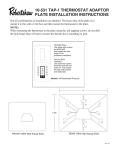
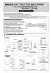
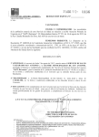
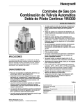
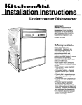
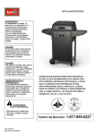
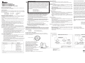
Recycling Thermostat
If this thermostat REPLACES a thermostat that contains mercury, DO
NOT discard the old thermostat in the regular trash. Mercury is harmful
to humans and the environment. For this reason, do not open, break, or
crush the mercury cell. If mercury leaks from a damaged cell, DO NOT
touch or handle mercury with bare hands. Use protective, non-absorbent
gloves to place mercury into a sealable container. Fill the container with
sand or another absorbent material and seal the container completely.
®
MECHANICAL THERMOSTAT
• MODEL 984-1R: COOLING ONLY
• MODEL 986-1R: HEATING ONLY
• MODEL 988-1R: HEATING and COOLING
INSTALLATION INSTRUCTIONS
Please read all instructions carefully before starting. Leave this instruction sheet
near the thermostat when you are finished.
SPECIFICATIONS
For use with self-powered 250-750 millivolt generating systems and 2 wire (Models
984 and 986) or 2, 3, 4 and 5 wire (Model 988) electric, gas or oil systems equipped
with 24 VAC controls.
Electrical Rating:
Heat Anticipator:
Cool Anticipator:
24 to 30 VAC
0.1 A to 1.2 A
0 to 1.5 A
(or 250-750mV)
(Adjustable)
(Fixed)
IMPORTANT SAFETY INFORMATION
• Always turn off power at the main power source (unscrew fuse or switch circuit
breaker to the off position) before installing, removing, cleaning, or servicing
thermostat.
• Read this manual entirely before installing this thermostat.
• This is a 24VAC low-voltage thermostat. Do not install on voltages higher than
30VAC.
• All wiring must conform to local and national building and electrical codes and
ordinances.
• Do not short (jumper) across terminals on the gas valve or relay to test the
installation. This will damage the thermostat and void the warranty.
• (For models 984-1R and 988-1R) To avoid damage to the air conditioner, do
not operate if the outside temperature is below 50°F. Please refer to the air
conditioner manufacturer’s recommendations.
SELECTING THERMOSTAT LOCATION
For accurate temperature control and comfort, selecting the proper location is
very important. If this is a new installation, the guidelines below should be followed. When replacing an old thermostat, install the new thermostat in the same
location unless these guidelines suggest otherwise.
1. Locate the thermostat on an inside wall of a frequently occupied area (e.g., family room) about 4-5 feet above the floor.
2. Do not install the thermostat where there are unusual sources of heat, such
as in direct sunlight or near a radiator, duct vent, lamp, or fireplace.
3. Do not install the thermostat where there are unusual cooling sources such as an
outside wall, drafts from doors, windows, stairways or duct vents.
4. Do not install the thermostat where the air circulation is poor, such as in a
corner, alcove, or behind a door.
REMOVING OLD THERMOSTAT
1. Shut off electricity to your heating and/or cooling system by removing the
associated fuse or switching the circuit breaker off.
2. Remove the cover of the old thermostat. If you do not see the system
wires, then you wilI have to remove another section of the thermostat.
This may require the use of a screwdriver.
3. Observe the terminal markings of each wire. Label each wire with tape indicating the appropriate terminal markings to allow easy installation of the
Robertshaw thermostat.
4. After you have labeled the existing wires, remove the wires from the terminals.
5. Remove the old thermostat base from the wall.
,
,
INTERNAL FAN OPTION)
Return the mercury or mercury products, in a sealed container, to
Invensys Controls Americas or a local recycling center for proper
disposal. If you have any questions, call Robertshaw technical support at
1-800-445-8299.
Invensys Controls
28C Leigh Fisher Blvd.
El Paso, TX 79906
Attn: Mercury Recycling Center
6. Hold the Robertshaw thermostat in one hand. Carefully remove cover
from thermostat base by pulling upward gently. Remove the paper
barrier around the magnet before final installation. Failure to remove the
paper barrier will result in the switch mechanism not working properly.
7. Position thermostat base on wall and carefully feed existing wires
through opening. The Robertshaw thermostat must be leveled to
provide good appearance and reliable performance.
8. After you have finished positioning the Robertshaw thermostat, you can
mark the placement of the two screw holes for mounting. Set aside
thermostat base.
9. If you are mounting the thermostat on plasterboard or another type of
soft material, use the supplied plastic anchors. Use a 3/16” drill to make
two holes where the mounting holes have been marked. Insert the
anchors into the holes.
10. Feed the wires back through the base, then mount to wall with supplied
screws.
11. Connect the wires to their associated marked terminals.
12. Check all connections so that adjacent wires are not touching.
13. Replace the cover onto the base by snapping it into place.
14. Recheck the level to make sure the unit has not shifted.
15. Make sure the system selector switch is in the OFF position until you
are ready to check your wiring.
INTERNAL FAN OPTION (MODEL 988-1R ONLY)
For typical gas or oil heating systems, connect the G wire to the G1 gas/oil terminal of the Robertshaw thermostat to allow a natural system delay in fan operation
during the heat mode. If the heating system requires the fan to come on immediately with the heat (i.e., electric heating systems), then connect the G wire to the
G2 electric terminal.
G1 gas/oil:
G2 electric:
CHECK THE WlRING
THREE YEAR LIMITED WARRANTY
CAUTION: DO NOT jump across the gas valve or relay to test the
thermostat.This will destroy the thermostat and void the warranty.
The manufacturer warrants to the original contractor installer, or to the original
consumer user, each new Robertshaw thermostat to be free from defects in
materials and workmanship under normal use and service for a period of three
(3) years from date of purchase. This warranty and our liability does not apply to
batteries or the merchandise that have been damaged, caused by misuse, neglect, mishandling, alterations, improper installation, or use in a way other than in
accordance with the manufacturer recommendations and instructions.
Model 984-1R only:
CAUTION: To avoid damage to the air conditioner, do not operate if the outside
temperature is below 50°F (10°C). Please refer to the recommendations of the air conditioner’s manufacturer.
1. Slide the system selector switch to the COOL position and the fan switch
to the AUTO position.
2. Set the temperature 6° to 8° BELOW the room temperature. The cooling
system and fan should turn on.
3. Slide the system selector switch to the OFF position. The cooling system
should turn off.
Model 986-1R only:
1. Turn on the power to the furnace.
2. Adjust the temperature setting of the thermostat 6° to 8° ABOVE room temperature. The heating system should turn on. The fan may take a few minutes to turn on depending on the delay built into the furnace.
3. Adjust the temperature setting of the thermostat 6° to 8° BELOW room temperature. The heating system should turn off. Once again, the fan may have
a delay.
Model 988-1R only:
1. Turn on the power to the furnace.
2. Slide the system selector switch to the HEAT position and the fan switch
to the AUTO position.
3. Adjust the temperature setting of the thermostat 6° to 8° ABOVE room temperature. The heating system should turn on. The fan may take a few minutes to turn on depending on the delay built into the furnace.
4. Slide the system switch to the OFF position. The heating system should
turn off. Once again the fan may have a delay.
The manufacturer agrees to repair or replace at its option any thermostat under
warranty provided it is returned within the warranty period, postage prepaid, with
proof of the date of purchase. Cost of thermostat removal or reinstallation is not
the responsibility of the manufacturer.
Repair or replacement as provided under this warranty is the exclusive remedy of
the consumer. The manufacturer shall not be liable for any incidental or consequential damages for breach of any express or implied warranty of this product,
or under any other theory of liability. Except to the extent prohibited by applicable
law, any implied warranty of merchantability or fitness for a particular purpose on
the product is limited to the duration of the warranty.
Some states do not allow the exclusion or limitation of incidental or consequential
damages, or allow limitations on how long an implied warranty lasts, so the
above limitations or exclusions may not apply to you. This warranty gives you
specific legal rights. You also may have other rights which vary from state to
state.
Instructions for return: Pack the thermostat carefully in a well-padded carton. Be sure
to include a note describing in detail what is wrong with the product. Return, postage prepaid, to:
Invensys Controls
515 South Promenade Avenue
Corona, CA 92879-1736
Attn: Warranty Department
CAUTION: To avoid damage to the air conditioner, do not operate it if the outside
temperature is below 50° F (10°C). Please refer to the recommendations of the air conditioner’s manufacturer.
5. Slide the system selector switch to the COOL position, and the fan switch
to the AUTO position.
6. Set the temperature 6° to 8° BELOW the room temperature. The cooling
system and fan should turn on.
7. Slide the system selector switch to the OFF position. The cooling system
should turn off.
Technical Service Available
M-F 7:30 AM to 5:30 PM CST
Inside US telephone: (800) 445-8299
Fan on with delay in heat
Fan on immediately with heat
SETTING THE HEAT ANTICIPATOR
To help provide accurate control of furnace heat cycles, you must adjust the
anticipator setting of the Robertshaw thermostat to match the current rating of
the system control device.
WIRING DIAGRAMS
One Transformer
Two Transformers
984-1R986-1,
986-1R
988-1R
MODELS 984-1,
988-1
MODEL 988-1
MODELS
988-1R
THERMOSTAT
THERMOSTAT
For longer ON times
W
This setting can be found by looking at the
setting used on the previous thermostat. If
you are unable to find it, the information can
be found in the owner’s manual for the
heating system. You can also find the
information printed on the control device at
the furnace. The control device is normally a
gas valve, relay, or pilot generator located
behind the furnace cover.
If the current rating is still unavailable,
connect an AC ammeter between the RH and
W terminals on the thermostat. Let the
system operate through the
ammeter for at least one minute before taking
the reading. This reading can be used as the
setting for the anticipator.
G1
G2
G1
G2
Y
RC
**
HEATING
CONTROL
RH
*
COOLING
CONTROL
**
L1
RH
REMOVE
FACTORY
INSTALLED
JUMPER
*
L1
L1
HOT
24 VAC
RC
Y
W
FACTORY
INSTALLED
JUMPER
HOT
120 VAC
120 VAC
COMMON
HEATING
24 VAC CONTROL
HOT
COOLING
CONTROL
24 VAC
120 VAC
COMMON
COMMON
L2
L2
L2
0.4 AMP
*
**
Current Rating
Fan control for gas or oil heating systems
Fan control for electric heating systems
*
**
Fan control for gas or oil heating systems
Fan control for electric heating systems
Typical Gas Valve
If your system is a millivolt system, set the anticipator to 1.2.
Terminal designations:
984-1R: Y, G, R
986-1R: W, R
988-1R: W, G, Y, RC, RH
191 E. North Avenue
Carol Stream, IL 60188
United States of America
110-330H
®
TERMOSTATO MECÁNICO
• MODELO 984-1R: SÓLO PARA AIRE ACONDICIONADO
• MODELO 986-1R: SÓLO PARA CALEFACCIÓN
• MODELO 988-1R: CALEFACCIÓN Y AIRE ACONDICIONADO
INSTRUCCIONES DE INSTALACIÓN
Por favor, lea todas las instrucciones cuidadosamente antes de empezar. Deje esta
hoja de instrucciones al lado del termostato una vez que haya finalizado.
ESPECIFICACIONES
Para uso con sistemas de generadores auto-alimentados de 250-750 milivoltios y
sistemas de aceite, gas o electricidad de 2 cables (Modelo 984 y 986) o 2, 3, 4 y 5
cables (Modelo 988), equipados con controles de 24 voltios/CA.
Rango Eléctrico:
24 a 30 voltios/CA (o 250-750mV)
Anticipador de Calor: 0.1 A a 1.2 A
(Ajustable)
Anticipador de Frío: 0 a 1.5 A
(Fijo)
INFORMACIÓN IMPORTANTE DE SEGURIDAD
• Apague siempre el interruptor general de electricidad (desatornille el fusible o
apague el interruptor automático[breaker]) antes de instalar, extraer, limpiar o
dar mantenimiento al termostato.
• Lea enteramente este manual antes de instalar este termostato.
• Este es un termostato de bajo voltaje a 24 voltios/CA. No lo instale en voltajes
superiores a 30 voltios/CA.
• Todo el cableado debe estar conforme a los códigos eléctricos y ordenanzas
de edificios locales y nacionales.
• No provoque corto circuitos a través de las terminales en la válvula de gas o relé
para probar la instalación. Esto dañará el termostato y anulará la garantía.
• (Para modelos 984-1R y 988-1R) Para evitar daños al aire acondicionado, no lo haga
funcionar si la temperatura exterior está por debajo de 10° Centígrados. Por favor
remítase a las recomendaciones del fabricante del aire acondicionado.
SELECCIÓN DE LA LOCALIZACIÓN DEL TERMOSTATO
Para un control preciso de temperatura y comodidad, es muy importante seleccionar la localización adecuada. Si esta es una instalación nueva, la guía de abajo
debería ser usada. Cuando se cambie un termostato antiguo, instale el nuevo en el
mismo sitio a no ser que estas guías sugieran lo contrario.
1. Ubique el termostato sobre una pared de interiores de un área de uso frecuente (p. ej.
una sala familiar) a unos 1.5 a 2 metros por encima del nivel del suelo.
2. No instale el termostato donde haya fuentes inusuales de calor tales como luz
directa del sol o cerca de un radiador, ducto de ventilación, lámparas, o chimenea.
3. No instale el termostato donde haya fuentes de frío inusuales tales como una pared
exterior, corrientes de aire de las puertas, ventanas, escaleras o ductos de ventilación.
4. No instale el termostato donde haya poca circulación de aire, como en una
esquina, hueco, o detrás de una puerta.
REMOCIÓN DEL ANTIGUO TERMOSTATO
1. Apague la corriente de su calefactor y/o sistema de aire acondicionado extrayendo el fusible correspondiente o apagando el interruptor automático (breaker).
2. Extraiga la cubierta del termostato antiguo. Si no ve el entramado de
cables, entonces tendrá que extraer otra sección del termostato. Esto
puede que requiera el uso de un destornillador.
3. Observe las marcas a los extremos de cada cable. Etiquete cada cable
indicando adecuadamente la marca del extremo para permitir una fácil
instalación del termostato Robertshaw.
4. Después de haber etiquetado los cables existentes, extraiga los cables
de las terminales.
5. Retire la base del termostato de la pared.
Terminal del termostato antiguo
M, 4, RH, R5 o 5
Etiqueta
nueva
RH
V o RC
RC
H, W. o 4
Y, o Y6
FoG
W
Y
G
Descripción
Transformador del calefactor, extremo caliente
(ver nota 1)
Transformador del aire acondicionado, extremo
caliente (ver nota 1)
Control del calefactor (válvula, relé, etc.)
Control del aire acondicionado (válvula, relé, etc.)
Relé del control del ventilador (ver OPCIÓN DE
VENTILADOR INTERNO)
NOTA 1: Si usted tiene cables terminales de conexión RH y RC separados, debe extraer el
puenteador (jumper) instalado de fábrica entre el RH del termostato y las terminales RC.
Reciclaje del termostato
Si este termostato REEMPLAZA a un termostato que contiene mercurio,
NO deseche el termostato anterior en la basura. El mercurio es dañino
para el ser humano y el medio ambiente. Por este motivo, nunca abra,
rompa o comprima la celda de mercurio. Si hay alguna fuga de mercurio
proveniente de una celda dañada, NO toque ni maneje el mercurio con las
manos desnudas. Use guantes de protección no absorbentes para colocar
el mercurio dentro de un recipiente con cierre hermético. Llene el recipiente
con arena u otro material absorbente y séllelo completamente.
Devuelva el mercurio o los productos con mercurio, dentro de una
recipiente sellado, a Invensys Controls Americas o al centro local de
reciclado para su disposición apropiada. Si tiene alguna duda, llame al
departamento de servicio técnico de Robertshaw al 1-800-445-8299.
Invensys Controls Americas
28C Leigh Fisher Blvd.
El Paso, TX 79906
Attn: Mercury Recycling Center
6. Sostenga el termostato Robertshaw en una mano. Extraiga con cuidado
la cubierta de la base del termostato tirando hacia arriba lentamente.
Retire la protección de papel que envuelve al imán antes de su instalación final. El no hacerlo podría ocasionar que el mecanismo del interruptor no funcione adecuadamente.
7. Posicione la base del termostato en la pared y meta con cuidado los cables ya
existentes a través de la abertura. El termostato Robertshaw debe ser nivelado
para brindar una buena apariencia y un desempeño confiabe.
8. Una vez que haya acabado de definir la posición del termostato
Robertshaw, puede marcar el emplazamiento de los agujeros para los
tornillos de montaje. Deje la base del termostato a un lado.
9. Si está montando la base del termostato en una superficie de cartón-yeso o
cualquier otra superficie blanda, utilice las anclas de plástico suministradas.
Use un taladro de 3/16" para hacer los dos agujeros que han sido señalados. Introduzca las anclas en dichos agujeros.
10. Introduzca nuevamente los cables a través de la base, después monte
la base en la pared con los tornillos suministrados.
11. Conecte los cables con sus respectivas terminales marcadas.
12. Revise todas las conexiones para asegurarse de que no hayan cables contiguos
en contacto.
13. Vuelva a poner la cubierta en la base mediante un golpe seco.
14. Vuelva a comprobar la posición para asegurarse de que la unidad no se ha movido.
15. Asegúrese de que el selector de sistema está en la posición OFF hasta
que decida probar su cableado.
OPCIÓN VENTILADOR INTERNO (ÚNICAMENTE MODELO 988-1R)
Para un sistema típico de calefacción por gas o por aceite, conecte el cable G a
la terminal G1 de gas/aceite del termostato Robertshaw para permitir un sistema
espontáneo de retardo en la operación del ventilador durante el modo de calefacción. Si el sistema de calefacción requiere que el ventilador comience inmediatamente junto a la calefacción (p. ej. Sistemas de calefacción eléctricos),
entonces conecte el cable G a la terminal eléctrica G2.
G1 gas/aceite: Ventilador encendido con retardo respecto a calefacción
G2 eléctrico: Ventilador encendido inmediatamente junto a la calefacción
AJUSTE DEL ANTICIPADOR DE CALOR
Para ayudar a brindar un control preciso de los ciclos de calor del calefactor,
debe ajustar el anticipador del termostato Robertshaw para igualarlo con el
rango actual del dispositivo de control de sistema.
Este ajuste se puede encontrar
previa revisión del ajuste utilizado en
el anterior termostato. Si por alguna
razón no le es posible encontrarlo, la
Para tiempos de
información se puede encontrar en
ENCENDIDO mayores
el manual del propietario del sistema
de calefacción. También puede
encontrar la información impresa en
el dispositivo de control en el
calefactor. El dispositivo de control
normalmente es una válvula de gas,
relé, o generador piloto localizado
detrás de la cubierta del calefactor.
Si aún así no encuentra el rango,
conecte un amperímetro de CA entre las
terminales RH y W del termostato. Deje
que el sistema opere a través del
amperímetro durante al menos un minuto
antes de que pueda registrar cualquier
lectura. Esta lectura se puede usar como
el ajuste para el anticipador.
Si su sistema es un sistema de milivoltios, ajuste el anticipador a 1.2.
REVISE EL CABLEADO
GARANTÍA LIMITADA A TRES AÑOS
CUIDADO: NO haga puente (jump) a través de la válvula de gas o relé para probar el termostato. Esto destruirá el termostato y anulará la garantía.
El fabricante garantiza al instalador original del contrato, o al cliente usuario original, que cada nuevo termostato Robertshaw se encuentra sin defecto alguno en
sus componentes o en la fabricación en condiciones de uso normal y servicio por
un período de tres (3) años desde la fecha de compra. Esta garantía y nuestra
responsabilidad no aplica a baterías ni a las mercancías que se han dañado por
causa de maltrato, negligencia, alteraciones, instalación indebida, u otro uso que
el recomendado en las instrucciones del fabricante.
Únicamente modelo 984-1R:
CUIDADO: Para evitar daños al aire acondicionado, no lo haga funcionar si la
temperatura exterior está por debajo de 10° C. Por favor remítase a
las recomendaciones del fabricante del aire acondicionado.
1. Ponga el interruptor de selector de sistema en la posición de COOL
(ENFRIAMIENTO) y el interruptor del ventilador en la posición de AUTO.
2. Ajuste la temperatura entre 6 a 8 grados POR DEBAJO de la tempe-ratura de la habitación. El sistema de aire acondicionado y el ventilador
deberían encenderse.
3. Ponga el interruptor de selector de sistema en la posición de (OFF)
APAGADO. El sistema de aire acondicionado debería apagarse.
Únicamente modelo 986-1R:
1. Encienda la corriente del calefactor.
2. Ajuste la temperatura del termostato entre 6° a 8° POR ENCIMA de la temperatura de la habitación. El sistema de calefacción debería encenderse. En
ventilador puede llegar a tomar varios minutos antes de encenderse dependiendo del retardo instalado en el calefactor.
3. Ajuste la temperatura del termostato de entre 6° a 8° POR DEBAJO de la
temperatura de la habitación. El sistema de calefacción debería apagarse.
Otra vez, puede que el ventilador experimente un retardo.
Únicamente modelo 988-1R:
1. Encienda la corriente eléctrica del calefactor.
2. Ponga el interruptor en la posición de HEAT (CALEFACCIÓN) y el interruptor del ventilador en la posición de AUTO.
3. Ajuste la temperatura del termostato de entre 6° a 8° POR ENCIMA de la
temperatura de la habitación. El sistema de calefacción debería encenderse.
En ventilador puede llega.
4. Ponga el interruptor de selector de sistema en la posición de APAGADO. El sistema
de enfriamiento debería apagarse. Otra vez, puede que el ventilador
experimente un retardo.
Válvula de gas típica
Rango de Corriente
La reparación o el cambio como lo prevee esta garantía es el recusro exclusivo
del cliente. El fabricante no se responsabiliza de cualquier daño incidental o por
consecuencia de violación de cualquier garantía expresa o implícita de este producto, o cualquier otra teoría de responsabilidad. Excepto en el caso de una prohibición aplicable por ley, cualquier garantía implicada de mercancía o aptitud
para un propósito particular en el producto está limitado a la duración de la
garantía.
Algunos estados no permiten la exclusión o limitación de daños incidentales o
por consecuencia de daños. O permiten limitaciones respecto a por cuanto tiempo dura una garantía, por lo que las limitaciones o exenciones arriba mencionadas puede que no apliquen en su caso. Esta garantía le otorga derechos
legales específicos. También puede llegar a tener otros derechos los cuales
varían de estado a estado.
Instrucciones para la devolución: Empaque el termostato con cuidado en una caja
bien acolchada. Asegúrese de incluir una nota describiendo en detalle que es lo que falla en
el producto. Devuélvalo, previo pago postal, a:
Invensys Controls
515 South Promenade Avenue
Corona, CA 92879-1736
Attn: Warranty Department
CUIDADO: Para evitar daños al aire acondicionado, no lo haga funcionar si la temperatura exterior está por debajo de 10° C (50° F). Por favor refiérase a
las recomendaciones del fabricante del aire acondicionado.
5. Ponga el interruptor de selector de sistema en la posición de COOL
(Enfriamiento) y el interruptor del ventilador en la posición de AUTO.
6. Ajuste la temperatura de entre 6° a 8° grados POR DEBAJO de la temperatura de la
habitación. El sistema de enfriamiento y el ventilador deberían encenderse.
7. Ponga el interruptor de selector de sistema en la posición de APAGADO
(OFF). El sistema de enfriamiento debería apagarse.
Servicio Técnico Disponible
Lunes a viernes 7:30 AM a 5:30 PM Tiempo del Centro (CST)
Teléfono dentro de los EE.UU: (800) 445-8299
DIAGRAMAS DE CABLEADO
Un transformador
Dos transformadores
MODELOS 984-1,
988-1
984-1R986-1,
986-1R
988-1R
MODELO
MODELOS988-1
988-1R
TERMOSTATO
TERMOSTATO
G1
G2
G1
G2
W
Y
RC
**
CONTROL
CALEF.
RH
*
CONTROL
AIRE ACO.
**
L1
RH
EXTRAIGA EL
PUENTEADOR
INSTALADO
DE FÁBRICA
*
L1
L1
CAL.
24 v/CA
RC
Y
W
PUENTEADOR
INSTALADO
DE FÁBRICA
CAL.
120 v/CA
120 v/CA
COMÚN
CONTROL
24 v/CA CALEF.
CALIENTE
CONTROL
AIRE ACO.
24 v/CA
L2
L2
Control de ventilador para sist. de calef. de
aceite o gas
Control de ventilador para sistemas de
calef. eléctricos
120 v/CA
COMÚN
COMÚN
L2
*
**
0.4 AMP
El fabricante acuerda reparar o cambiar dentro de sus posibilidades cualquier
termostato bajo garantía que se otorgue dentro de dicho período, previo pago
postal, con comprobante de la fecha de compra. El costo de transporte o reinstalación no es responsabilidad del fabricante.
*
**
Control de ventilador para sist. de calef. de
aceite o gas
Control de ventilador para sistemas de
calef. eléctricos
Designaciones de terminal:
984-1R: Y, G, R
986-1R: W, R
988-1R: W, G, Y, RC, RH
191 E. North Avenue
Carol Stream, IL 60188
United States of America
110-330H