1
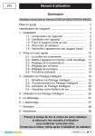
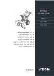
Owner’s Manual
Notice d’utilisation
Manual del Propietario
Do not use this equipment before
reading this manual!
CAPSpray 115
HVLP Spray System
Model
0524034
Register your product online at:
NOTE: This manual contains important
warnings and instructions. Please
read and retain for reference.
www.titantool.com
Proper registration will serve as proof of purchase in the event your
original receipt becomes misplaced or lost.
Serial Number*
* See page 5 for location
__________
0412 •
© T tan Too Inc. A R ghts Reserved. Form No. 0524858F
Important Safety Information ·
Read all safety information before
operating the equipment. Save these instructions.
HAZARD:HAZARDOUS VAPORS
Pa nts, so vents, nsect c des, and other mater a s can be
harmfu f nha ed or come n contact w th the body. Vapors
can cause severe nausea, fa nt ng, or po son ng.
PREVENTION:
• Use a resp rator or mask f vapors can be nha ed.
Read a nstruct ons supp ed w th the mask to be
sure t w prov de the necessary protect on.
• Wear protect ve eyewear.
• Wear protect ve c oth ng as requ red by coat ng
manufacturer.
This symbol indicates a hazardous situation, which, if not
not avoided could result in death or serious injury.
To reduce the risks of fire or explosion, electrical shock
and the injury to persons, read and understand all
instructions included in this manual. Be familiar with the
controls and proper usage of the equipment.
HAZARD:
EXPLOSION HAZARD DUE TO
INCOMPATIBLE MATERIALS
W cause property damage or severe njury.
PREVENTION:
• Do not use mater a s conta n ng b each or ch or ne.
• Do not use ha ogenated hydrocarbon so vents such as b each,
m dewc de, methy ene ch or de and 1,1,1 - tr ch oroethane. They
are not compat b e w th a um num.
• Contact your coat ng supp er about the compat b ty of mater a
w th a um num.
HAZARD: Skin burn injury
Heated parts can cause severe sk n burn njury.
PREVENTION:
• Qu ck d sconnect fitt ngs on the hose and spray gun
become hot dur ng use. Avo d sk n contact w th qu ck d sconnect
fitt ngs when they are hot. A ow qu ck d sconnect fitt ngs to coo
before d sconnect ng the spray gun from the hose.
HAZARD: GENERAL
Can cause severe njury or property damage.
PREVENTION:
• Read a nstruct ons and safety precaut ons before operat ng any
equ pment.
• Fo ow a appropr ate oca , state, and nat ona codes govern ng
vent at on, fire prevent on, and operat on.
• The Un ted States Government Safety Standards have been
adopted under the Occupat ona Safety and Hea th Act (OSHA).
These standards, part cu ar y Part 1910 of the Genera Standards
and Part 1926 of the Construct on Standard shou d be consu ted.
• Use on y manufacturer author zed parts. User assumes a r sks
and ab t es when us ng parts that do not meet the m n mum
spec ficat ons and safety dev ces of the manufacturer.
• Before each use, check all hoses for cuts, leaks, abrasion or
bulging of cover. Check for damage or movement of couplings.
Immediately replace the hose if any of these conditions exist.
Never repair a hose. Replace it with an identical replacement hose.
• Do not spray outdoors on w ndy days.
• Wear c oth ng to keep pa nt off sk n and ha r.
• Never a m the spray gun at any part of the body.
Grounding Instructions
Th s product must be grounded. In the event of an e ectr ca short c rcu t,
ground ng reduces the r sk of e ectr c shock by prov d ng an escape
w re for the e ectr c current. Th s product s equ pped w th a cord hav ng
a ground ng w re w th an appropr ate ground ng p ug. The p ug must
be p ugged nto an out et that s proper y nsta ed and grounded n
accordance w th a oca codes and ord nances.
warning - Improper installation of the grounding plug can result in
a risk of electric shock.
If repa r or rep acement of the cord or p ug s necessary, do not connect
the green ground ng w re to e ther flat b ade term na . The w re w th
nsu at on hav ng a green outer surface w th or w thout ye ow str pes s
the ground ng w re and must be connected to the ground ng p n.
Check w th a qua fied e ectr c an or serv ceman f the ground ng
nstruct ons are not comp ete y understood, or f you are n doubt as
to whether the product s proper y grounded. Do not mod fy the p ug
prov ded. If the p ug w not fit the out et, have the proper out et nsta ed
by a qua fied e ectr c an.
Grounded Outlet
HAZARD: EXPLOSION OR FIRE
So vent and pa nt fumes can exp ode or gn te. Property
damage and/or severe njury can occur.
PREVENTION:
• Exhaust and fresh a r ntroduct on must be prov ded
to keep the a r w th n the spray area free from
accumu at on of flammab e vapors.
• Turb ne conta ns spark ng parts. Turb ne must
be p aced n a we vent ated area at max mum
d stance from the spray area.
• Avo d a gn t on sources such as stat c e ectr c ty, open flames,
p ot ghts, hot objects, c garettes, and sparks from connect ng
and d sconnect ng power cords and work ng ght sw tches.
• Use extreme caut on when us ng mater a s w th a flashpo nt be ow
70° F (21°C). A flu d’s flashpo nt s the temperature at wh ch
vapors from the flu d cou d gn te f exposed to a flame or spark.
• F re ext ngu sh ng equ pment must be present and n work ng
order.
• The power cord must be connected to a grounded c rcu t.
• Fo ow the mater a and so vent manufacturer’s safety precaut ons
and warn ngs.
Grounding Pin
Cover for grounded outlet box
IMPORTANT: Use only a 3-wire extension cord that has a 3-blade
grounding plug and a 3-slot receptacle that will accept the plug on
the product. Make sure the extension cord is in good condition.
When using an extension cord, be sure to use one heavy enough
to carry the current the product will draw. An undersized cord
will cause a drop in line voltage resulting in loss of power and
overheating. A 12 gauge cord is recommended. If an extension cord
is to be used outdoors, it must be marked with the suffix W-A after
the cord type designation. For example, a designation of SJTW-A
would indicate that the cord would be appropriate for outdoor use.
NOTE: More than 100 feet of extension cord is not
recommended. Use more paint hose, not more
extension cord. Shorter extension cords will assure
maximum electrical power for proper operation.
Service
Shou d your spray system need serv ce dur ng the warranty per od,
return your un t and the proof of purchase to the d str butor where t was
purchased. At our opt on, the un t w be repa red or rep aced. In a
cont nued comm tment to mprove qua ty, we reserve the r ght to make
component or des gn changes when necessary.
English
2
© Titan Tool Inc. All rights reserved.
Table of Contents
Spray gun
Safety.......................................................................................... 2
Grounding Instructions........................................................... 2
Service........................................................................................ 2
Introduction................................................................................ 3
Using an HVLP Spray System.................................................. 3
Setup...................................................................................... 3
Dual Filtration System............................................................ 3
Maintenance............................................................................... 4
Cleaning/Replacing Filters...................................................... 4
Cleaning the Air Hoses........................................................... 4
Troubleshooting........................................................................ 5
Product Registration................................................................. 5
Français...................................................................................... 6
Español.................................................................................... 10
Parts List............................................................................. 14-17
Wiring Diagram........................................................................ 18
Warranty................................................................................... 20
Turbine
Air hose
Setup
Use the following procedure to set up your HVLP spray system
for operation.
1. Plug the turbine power cord into a grounded, 3-slot
receptacle.
This High Volume/Low Pressure (HVLP) spray system is designed
for applying coatings to surfaces that can be sprayed faster
than brushing or rolling and are too small for traditional airless
sprayers. Components of this system include a power switch, a
power cord, a filter warning light, a circuit breaker switch, a dual
filtration system, a cup holder, an air hose, and an air outlet.
The power switch comes with two speed settings. Low speed is
generally used for light-bodied materials. High speed is ideal for
thicker materials.
The turbine is also equipped with a tool box. It is located on the
reverse side of the turbine and can be used to store projector
sets or any other small spare parts.
2.
3.
4.
5.
Keep the turbine at the maximum possible distance
from the spray area to safeguard against explosion
or fire that may be caused by sparking electrical
parts.
Prepare your spray gun for operation. Refer to your spray
gun manual for material preparation, setup, and spraying
information.
Attach the air hose to the air outlet on the turbine.
Attach the air hose to the air inlet on your spray gun.
Turn on the turbine and begin spraying.
Dual Filtration System
The turbine has two different air filters— one for atomizing air
and one for cooling air. The atomizing air filter is a two-stage,
fine mesh filter designed to trap particles that may damage your
finish. The atomizing air is discharged through the nozzle of the
spray gun where it atomizes the coating material. The cooling air
filter is a coarse mesh filter designed to allow the proper amount
of air flow through the turbine for cooling purposes. Cooling air
is exhausted through the cooling air discharge on the front of the
turbine.
Cup holder
Filter
warning
light
Whip hose
important: Do not attach the short air whip hose directly
to the turbine, as the hose will become damaged.
Introduction
Circuit
breaker
switch
Coupling
Atomizing air
discharge
Air inlet
Rear of turbine
Atomizing air
intake
Filter
(in end of
filter can)
Filter
Power switch /
Speed selector
Air outlet
Cooling air
intake
*Air hose not pictured
With this HVLP spray system, you can achieve the highest quality
professional finish possible with little or no preparation or setup
time. Please review all the information contained in this manual
before operating the system.
Filter Warning System
The filter warning system on your turbine consists of a red filter
warning light on the front control panel and an air flow switch
inside the turbine. When the air flow switch does not detect the
appropriate amount of air flowing through the turbine, the filter
warning light will come on to indicate that it is time to clean or
change the filters.
Using an HVLP Spray System
Refer to the following information to operate and understand your
HVLP spray system.
Your system may include a short air (“whip”) hose. The
short hose should be connected to the longer hose or a
remote spraying system (sold separately) and NOT directly
to the turbine. See your spray gun instruction manual for
complete instructions.
© Titan Tool Inc. All rights reserved.
Cooling air
discharge
NOTE: The filter warning system does not shut down the
turbine.
IMPORTANT: Clean filters regularly. Clogged filters can
cause excessive heat and possibly damage the turbine.
3
English
3. Clean the filters. Either tap the filters to knock out the
contaminants or use pressurized air to blow out the
contaminants. For material that is not blown or knocked
loose easily, soak the filters in soapy water or mineral
spirits. Allow the filters to dry completely before placing
them back in the turbine.
Maintenance
Use the following procedures to keep your HVLP spray system
running properly.
Cleaning / Replacing the Filters
important: Make sure the turbine is unplugged before
changing the filters.
1. Remove the filter covers on each side of the turbine by
turning them counterclockwise.
NOTE: Do not use highly flammable solvents, such as
lacquer thinner, to clean the filters.
IMPORTANT: Do not soak paper pleated filter in solvents.
Only tap the filter or use compressed air directed at the
inside (the clean side)
4. Insert each filter back into its corresponding filter can.
NOTE: Make sure the white pleated filter is fitted
securely to the spokes of the filter can. Turn
clockwise to secure in place.
5. Replace the filter covers on each side of the turbine by
turning them clockwise.
After several cleanings, it may become necessary to replace the
filters. Refer to the parts list near the end of this manual for the
filter replacement kit part number.
Cleaning the Air Hoses
Filter cover
1. Periodically wipe the outer surface of the air hose with a
damp cloth to keep clean.
2. Remove each filter set (pre-filter and filter) from the filter
housing on each side of the turbine.
IMPORTANT: DO NOT submerge into or flush the air hose
with water or any chemical.
NOTE: The white pleated filter is removed from the
turbine in the same manner as the filter cover. Turn counterclockwise to unlock and remove.
IMPORTANT: DO NOT use methylethylketon (MEK),
naphtha, mineral spirits, paint thinner, xylol/xylene, or toluel/
toluene to clean the air hose. Exposure over time could
cause damage to the hose.
Filter cover
IMPORTANT: Store indoors with the cord wrapped around
the handle.
Pre-filter
Filter
White pleated filter
Pre-filter
Filter cover
English
4
© Titan Tool Inc. All rights reserved.
Troubleshooting
Problem
Cause
1. A r flow adjustment knob on the spray gun
s turned off
Solution
1. Adjust the a r flow adjustment knob
2. A r fi ters are c ogged
2. C ean or rep ace the fi ters
B. F ter warn ng ght s on
1. A r fi ters are c ogged
1. C ean or rep ace the fi ters
C. The turb ne has no power
1. No power at the power supp y
1. Check the power supp y
2. C rcu t breaker has been tr pped.
2. Reset the breaker. If prob em pers sts, have turb ne
nspected at an author zed T tan serv ce center.
3. Worn turb ne brushes
3. Have the brushes rep aced at an author zed T tan
serv ce center
1. Worn turb ne brushes
1. Have the brushes rep aced at an author zed T tan
serv ce center
2. Damaged commutator
2. Rep ace the turb ne (contact a T tan serv ce
techn c an)
A. Restr cted a r flow or no a r
flow
D. Excess ve arc ng/spark ng n
the turb ne
IMPORTANT:
Product Registration
• The turbine motor can be damaged if not serviced
properly. Have the brushes (Kit P/N 0277243) checked for
wear by an authorized service center every 400 hours.
• Clean filters regularly. When the filter warning light comes
on, it is time to clean the filters. Clogged filters cam cause
excessive heat and possibly damage the unit.
• For additional troubleshooting information, see the manual
that came with your gun.
Register your product online at www.titantool.com. Proper
registration will serve as proof of purchase in the event your
original receipt becomes misplaced or lost.
Serial Number Location
Specifications
Air pressure������������������� 11.5 psi
Power���������������������������� 120VAC, 60 Hz, 15.0 A
Turbine weight��������������� 24.0 lbs
Main hose length����������� 30 ft
Whip hose length����������� 5 ft
Spray gun included�������� Maxum II
xxx
xxx
x
Patents
These products are covered by one or more of the following U.S. patents:
D623,660 5,550,336
5,556,255
5,639,222
5,702,131
5,558,492
5,772,711
Titan 30-Day Satisfaction Guarantee
If, within a 30-day period from the date of purchase, you are not totally satisfied with a Titan unit, you may return it for full credit
toward another Titan product of equal or greater value.
© Titan Tool Inc. All rights reserved.
5
English
Parts List • Liste de pièces • Lista de piezas
Main Assembly •
Vue d’ensemble •
7
Ensamblaje principal
1
10
9
16
2
6
15
3
4
14
3
5
6
7
8
16
9
10
13
16
11
12
Item
Art.
Art.
Part No.
Nº de piéce
Pieza No.
Français
Description
Español
Descripción
1
Upper housing assembly (see separate
listing)
Ensemble de boîtier supérieur (voir liste
séparée)
Ensamblaje de caja superior (consulte la
lista separada)
1
2
6 Stage turbine assembly 120V (see
separate listing)
Turbine en six pièces 120 V (voir liste
séparée)
Conjunto de la turbina 6 fases (consulte
la lista separada)
1
Sidewall silencer
Silencieux
Silenciador
2
Silencer assembly
Ensemble de silencieux
Conjunto de silenciador
1
Sealing foam
Mousse d étanchéité
Espuma de sellado
1
3
0524927
4
0524593A
5
0524524
6
0524948A
Filter can
Carters de filtre
Recipiente del filtro
2
7
0293395
Screw
Vis
Tornillo
10
8
0524523A
Filter
Filtre
Filtro
1
9
0524526A
Pre filter
Préfiltre
Pre filter
2
10
0524949A
Filter cover
Carter du filtre
Cubierta de filtro
2
Lower housing assembly (see separate
listing)
Ensemble de boîtier inférieur (voir liste
séparée)
Ensamblaje de caja fondo (consulte la
lista separada)
1
11
12
858 634
Screw
Vis
Tornillo
4
13
0524596
Exhaust ring
Anneau d échappement
Anillo de escape
1
14
0524926
Silencer assembly
Ensemble de silencieux
Conjunto de silenciador
1
15
0524528A
Filter
Filtre
Filtro
1
16
0524594
Foam tape
Bande de mousse
Cinta de espuma
4
0277337
Air hose (not pictured)
Tuyau pour l air (pas d illustration)
Manguera de aire (no se muestra)
1
0153165
Viscosity cup (not pictured)
Godet de viscosimètre (pas d illustration)
Cubeta de viscosidad (no se muestra)
1
0275625
Quick disconnect female (not pictured)
Raccord rapide (pas d illustration)
Accesorio de desconexión rápida (no se
muestra)
1
Air hose whip (not pictured)
Tuyau pour l air de fouet (pas
d illustration)
Manguera de aire corta (con conexión
flexible) (no se muestra)
1
Spray gun (not pictured)
Pistolet (pas d illustration)
Pistola (no se muestra)
1
0524405A
0524027
Qty.
Qte.
Cant.
English
Description
English Français Español
14
© Titan Tool Inc. All rights reserved.
Turbine Assembly • Ensemble de turbine • Ensamblaje de turbina
9
8
7
6
5
4
3
2
1
Item
Art.
Art.
Part No.
Nº de piéce
Pieza No.
1
Qty.
Qte.
Cant.
English
Description
Français
Description
Español
Descripción
9810108
Nut
Écrou
Tuerca
12
2
9821503
Lock washer
Ronde e de fixat on
Arande a de asegurar
12
3
0524998
Can cover
Couverc e de carter
Cub erta de rec p ente
1
4
0524590
Spacer
Espaceur
Separador
3
5
0277469
Turb ne can sea
Jo nt d’étanché té de carter de turb ne
Junta de ata de a turb na
1
6
0524290A
7
0524591
8
0524971A
9
0524687
0277243
Motor brush k t
6-Stage turb ne assemb y, 120V
Turb ne en s x p èces, 120 V
Conjunto de a turb na, 6-fases, 120 V
1
Spacer
Espaceur
Separador
3
Can cover
Couverc e de carter
Cub erta de rec p ente
1
Motor shroud sea
Jo nt d’étanché té de carénage de
moteur
Junta de a carcasa de motor
1
Jeu de ba a s charbon
Juego de escob as de carbón
© Titan Tool Inc. All rights reserved.
15
Español Français English
Upper housing assembly • Ensemble de boîtier supérieur • Ensamblaje de caja superior
3
4
5
1
6
2
7
14
8
17
9
18
19
20
15
16
10
21
11
22
13
13
12
Item
Art.
Art.
Part No.
Nº de piéce
Pieza No.
1
2
Qty.
Qte.
Cant.
English
Description
Français
Description
Español
Descripción
0524537
Too box door
Porte de trousse d’out s
Puerta de a caja de herram entas
1
0524538
Too box
Trousse d’out s
Caja de herram entas
1
Top hand e
Po gnée supér eure
Man a super or
1
Upper hous ng
Boît er supér eur
Caja super or
1
0524558
Lower hand e
Po gnée nfér eure
Man a nfer or
1
9802266
Screw
Vs
Torn o
3
0524963
Lock washer
Ronde e de fixat on
Arande a de asegurar
1
0524694
Sw tch
Interrupteur
Interruptor
1
9
0524549
C rcu t breaker sw tch k t, 15A
L’équ pement de commutateur de
br seur de c rcu t, 15A
E conjunto de nterruptor de
rompedor de c rcu to, 15A
1
10
0524547
Warn ng ght assemb y, 120V
Voyant um neux, 120V
Conjunto de a uz de advertenc a,
120V
1
11
0524996
E ectr ca cover assemb y
Couverc e d’assemb age é ectr que
Conjunto de a cub erta e éctr ca
1
12
9803104
Screw
Vs
Torn o
6
13
0524536
Cup ho der
Porte-godet
Sostén de depós to
1
14
9805386
Screw
Vs
Torn o
2
15
9802265
Screw
Vs
Torn o
4
16
0524566
Cab e c amp
Br de de câb e
Abrazadera de cab e
4
17
0277475
Tube
Tube
Tubo
1
18
0277472
A r flow sw tch
Sé ecteur d’aérat on
Interruptor de flujo de a re
1
19
9802905
Screw
Vs
Torn o
1
20
0524626
W re assemb y
Ensemb e de câb es
Conjunto de cab es
1
21
9805287
Ground screw
V s de borne à a terre
Torn o de conex ón a t erra
1
22
9822106
Lock washer
Ronde e de fixat on
Arande a de asegurar
1
3
0524557
4
0524531A
5
6
7
8
English Français Español
16
© Titan Tool Inc. All rights reserved.
Lower housing assembly • Ensemble de boîtier inférieur • Ensamblaje de caja fondo
1
2
3
4
8
5
6
7
9
10
11
Item
Art.
Art.
Part No.
Nº de piéce
Pieza No.
1
2
Qty.
Qte.
Cant.
English
Description
Français
Description
Español
Descripción
9805387
Screw
Vs
Torn o
2
0277443
B eeder box cover
Couverc e de boîte de purge
Cub erta de a caja de purgador
1
3
0277442
B eeder box base
Base de boîte de purge
Base de a caja de purgador
1
4
9881911
Exhaust hose
Tuyau d’échappement
Manguera de escape
1
5
0327226
Hose c amp
Agrafe de compress on
Abrazadera de apretón
1
6
0276511
Exhaust hose fitt ng
Raccord de tuyau d’échappement
Adaptador de a manguera de escape
1
7
0524532A
Lower hous ng
Boît er nfér eur
Caja fondo
1
8
9802213
Screw
Vs
Torn o
4
9
0524592
Cord / stra n re ef
Cordon / détendeur
Cordón / desb oqueador
1
10
0090628
Foot pad
Coupe es
Amort guador de a base
5
11
9802222
Screw
Vs
Torn o
5
Français
Description
Español
Descripción
Labels • Étiquettes • Etiquetas
Part No.
Nº de piéce
Pieza No.
English
Description
0524853
Front cover abe
Ét quette du couverc e avant
Et queta de a cub erta de antera
0277630
Warn ng abe
Et queta de a cub erta de motor
Et queta de advertenc a
© Titan Tool Inc. All rights reserved.
17
Español Français English
Wiring Diagram • Diagramme électrique • Diagrama eléctrico
(P/N 0524547)
Warning light assembly
Voyant lumineux
Conjunto de la luz de advertencia
(P/N 0524549)
Circuit breaker
Briseur de circuit
Rompedor de circuito
(P/N 0524694)
ON/OFF switch
Interrupteur ON/OFF
Interruptor ON/OFF
(P/N 0277472)
Air flow switch
Sélecteur d'aération
Interruptor del flujo de aire
Turbine
Turbine
Turbina
(P/N 0524592)
Power cord
Cordon d’alimentation
Cable de alimentación
NOTE:All electrical work should be
performed by an authorized
service center.
NOTA : Tous les travaux d’électricité doivent
être effectués par le personnel d’un
centre de service autorisé.
English Français Español
18
NOTA: Todo trabajo eléctrico debe
realizarlo un centro de
servicio autorizado.
© Titan Tool Inc. All rights reserved.
Limited Warranty — High Volume/Low Pressure Spray Equipment
What Is Covered By This Warranty:
This product, manufactured by Titan, is warranted against defects in material and workmanship for one (1) year following date of
purchase if operated in accordance with Titan’s printed recommendations and instructions.
Within the applicable warranty period, Titan will repair or replace, at our option, defective parts without charge if such parts are
returned with transportation charges prepaid to the nearest Authorized Service Center or to Titan Tool Corporation, 1770 Fernbrook
Lane, Minneapolis, MN 55447. If Titan is unable to repair this product as to conform to this Limited Warranty after a reasonable
number of attempts, Titan will provide, at our option, either a replacement for this product or a full refund of the purchase price of this
product. These remedies are the sole and exclusive remedies available for breach of express and implied warranties.
What is Not Covered By This Warranty:
1. This Waranty does not cover any defects or damages caused by either:
a) the use or installation of repair or replacement parts or accessories not manufactured by Titan, or
b) repair performed by anyone other than a Titan Authorized Service Center.
2. The Warranty does not cover equipment and accessories supplied to Titan from an original equipment manufacturer,
including but not limited to: hoses, tips, or accessories. Titan will provide the purchaser with copies of the original equipment
manufacturer’s express warranties provided to Titan along with the name and address of the appropriate manufacturer.
3. This Warranty does not cover damage or defects caused by or related to abrasion, corrosion, abuse, misuse, negligence,
accident, normal wear, faulty installation, or tampering in a manner which impairs normal operation.
Limitation of Remedies:
IN NO CASE SHALL TITAN BE LIABLE FOR ANY INCIDENTAL, SPECIAL OR CONSEQUENTIAL DAMAGES OR LOSS,
INCLUDING TRANSPORTATION COSTS, WHETHER SUCH DAMAGES ARE BASED UPON A BREACH OF EXPRESS OR
IMPLIED WARRANTIES, BREACH OF CONTRACT, NEGLIGENCE, STRICT TORT, OR ANY OTHER LEGAL THEORY.
Disclaimer Of Implied Warranties:
THE FOREGOING WARRANTIES ARE IN LIEU OF ALL OTHER WARRANTIES, EXPRESS OR IMPLIED, INCLUDING BUT NOT
LIMITED TO THE IMPLIED WARRANTIES OF MERCHANTABlLlTY AND FITNESS FOR A PARTICULAR PURPOSE.
No Ability To Transfer:
This warranty is extended to the original purchaser only and is not transferable.
Your Rights Under State Law:
Some states do not allow limitations on how long an implied warranty lasts or the exclusion of incidental or consequential damages,
so the above limitation and exclusion may not apply to you. This warranty gives you specific legal rights, and you may also have other
rights which vary from state to state.
United States Sales & Service
Canadian Branch
International
Phone: 1-800-526-5362
Fax: 1-800-528-4826
Phone: 1-800-565-8665
Fax: 1-800-856-8496
Phone: 1-201-337-1240
Fax: 1-201-405-7449
200 Trowers Road, Unit 7B
Woodbridge, Ontario L4L 5Z8
1770 Fernbrook Lane
Minneapolis, MN 55447
1770 Fernbrook Lane
Minneapolis, MN 55447
www.titantool.com
English
20
© Titan Tool Inc. All rights reserved.