1
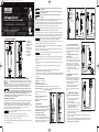
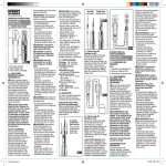
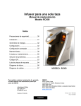
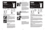
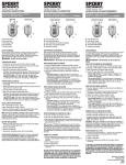
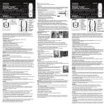
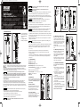
VC6300 Volt Doctor
7/24/06
10:33 AM
Page 1
is reserved for conditions and actions that can cause injury or
instrument damage.
VC6300
SPERRY
! DANGER
INSTRUMENTS
Volt Doctor
Never make measurement on a circuit in which voltage over
AC 600 V exists.
• Do not attempt to take measurements in the presence of flammable gasses. Otherwise,
the use of the instrument may cause sparking, which can lead to an explosion.
™
Beeper / Light
For
testing
probes
slide
down
from top
No Reaction
• This tester is designed for intermittent duty only (On 15 seconds, Off 240 seconds). It
should only take several seconds to note a voltage indication. If the reading is maintained
longer than 15 seconds, damage to the unit may occur.
Voltage and Continuity Tester
! WARNING Never attempt to use the instrument if its surface or your hand is wet.
• Read this owners manual thoroughly before use and save.
• Do not exceed the maximum allowable input of any measuring range.
• Never open the battery cover during a measurement.
2150 Joshua’s Path, Suite 302, Hauppauge, NY 11788
1-800-645-5398 • www.sperryinstruments.com
• The instrument is to be used only in its intended applications or conditions. Otherwise,
safety functions equipped with the instrument don’t work, and instrument damage or
serious personal injury may be caused.
Never attempt to make measurements if any abnormal conditions, such as
! WARNING
broken case or exposed metal parts are found on the instrument.
1.0 METER FUNCTIONS
1. DC Polarity Indicators
2. AC/DC Voltage Scale
3. Probe Holders and
Storage
4. Continuity Indicator
5. Battery Compartment
1
4
2
• Do not install substitute parts or make any modification to the instrument. For repair or
re-calibration, return the instrument to your local distributor from where it was purchased.
• Disconnect all the cords and cables from the object under test before opening the battery
cover for battery replacement.
• Verify proper operation on a known source before use or taking action as a result of the
indication of the instrument.
Use appropriate personal protective equipment such as insulating gloves,
insulating boots, and safety glasses.
• Do not expose the instrument to the direct sun, high temperature and humidity or dewfall.
• Using the meter in areas with high magnetic fields can result in inaccurate readings.
• Altitude 2000m or less. Appropriate operating temperature is within 32 °F – 104 °F
(0 °C – 40 °C).
3
• This instrument isn’t dust and water proofed. Keep away from dust and water.
• When the instrument will not be in use for a long period, place it in storage after
removing the batteries.
5
• Cleaning: Use a cloth dipped in water or neutral detergent for cleaning the instrument.
Do not use abrasives or solvents otherwise instrument may get damaged, deformed
or discolored.
3.0 SPECIFICATIONS
2.0 READ FIRST: IMPORTANT SAFETY INFORMATION
Read this operators manual thoroughly before using this meter. This manual
is intended to provide basic information regarding this meter and to describe
common test procedures which can be made with this unit. Many types of appliance,
machinery and other electrical circuit measurements are not addressed in this manual and
should be handled by experienced service technicians.
Use extreme caution when using this meter. Improper use of this
! WARNING
meter can result in severe damage to property, severe personal injury
or death. Follow all instructions and suggestions in this operators manual as well
as observing normal electrical safety precautions. Do not use this meter if you are
unfamiliar with electrical circuits and proper test procedures.
SAFETY WARNINGS
This instrument has been designed, manufactured and tested according to IEC61010:
Safety requirements for Electronic Measuring apparatus, and delivered in the best
condition after passing inspection. This instruction manual contains warnings and safety
rules which must be observed by the user to ensure safe operation of the instrument and
retain it in safe condition. Therefore, read through these operating instructions before using
the instrument.
DC Voltage: 120 - 600 Volts
AC Voltage: 120 - 600 Volts
AC Voltage Frequency: 50 - 60 Hz
Intermittent Duty Only! On 15 seconds, Off 240 seconds
Operation Environment: 32 °F – 104 °F (0 °C – 40 °C), 80% RH Max.
50% RH above 31 °C
4.0 OPERATION
This meter is designed with probe holders to
allow for maximum versatility and single hand
testing. Refer to the drawings in Fig. 1 for
common setups.
Automatic Operation
• The instrument is to be used only in its intended applications.
When using the test leads, the tester will
automatically activate when connected to
AC or DC voltage. The tester will
automatically select the proper function.
• Understand and follow all the safety instructions contained in the manual.
4.1 Testing Continuity
• It is essential that the above instructions are adhered to.
Touch the tip of the test leads to the points
where tests need to be made. If the
resistance is below 50 ohms, the continuity
light at the top will illuminate. Fig. 2
! WARNING Keep the manual at hand to enable quick reference whenever necessary.
• Failure to follow the above instructions may cause injury, instrument
damage and/or damage to equipment under test.
! DANGER
is reserved for conditions and actions that can cause serious
or fatal injury.
Fig. 1
Two
Hand
Fig. 2
4.2 Measuring DC Voltage Levels
Measure the voltage by touching the test
lead tips to the circuit where the value of
voltage is needed. If the yellow test lead is
on the positive contact the +VDC light will
illuminate. If the yellow test lead is on the
negative contact the -VDC light will
illuminate. Fig. 3
Read the voltage level from the DC voltage
scale.
4.3 Measuring AC Voltage Levels
Measure the voltage by touching the test
lead tips to the circuit where the
value of voltage is needed. Both polarity
indicators will illuminate to indicate AC
Voltage. Fig. 4
Read the level from the AC voltage scale.
The polarity of the leads does not matter
for AC voltage measurements.
Yellow
Black
Fig. 3
5.0 CHANGING THE BATTERIES
Altitude up to 2000 meters. Indoor use.
Storage Temperature: 14 °F – 140 °F (-10 °C – 60 °C)
Batteries: (2) 1.5 V button cells
CAT III 600V
Fig. 1
Single
Hand
Do not open tester case while using
the tester.
1) When the battery voltage drops below
proper operating range, the tester will
no longer function.
2) Slide rubber boot at the bottom of the
tester out of the way and remove the
screw to access the battery
compartment.
3) Slide the bottom out and replace with
(2) 1.5 Volt button cell batteries (LR44,
SR44, A76, G13, AG13, GP76A, 257,
D357, V13GA.
4) Replace battery door, screw and rubber
boot to original positions.
5) Test on known live circuit to verify proper
operation. Also test continuity function by
touching the two leads together.
(Refer to 1.0, Meter Functions)
Fig. 4
VC6300 Volt Doctor
7/24/06
10:33 AM
Page 2
VC6300
SPERRY
INSTRUMENTS
¡PELIGRO!
se reserva para condiciones y acciones que pueden causar lesiones
serias o fatales.
! PRECAUCION!
se reserva para condiciones y acciones que pueden causar lesiones
o daño al instrumento.
!
!
Voltage Doctor
™
!
¡PELIGRO!
Nunca tome medidas en un circuito donde exista voltaje sobre
600V de CA.
Probador de voltaje y continuidad
• No intente tomar medidas en la presencia de gases inflamables. De lo contrario, el uso del
instrumento puede causar chispas, lo cual puede ocasionar una explosión.
• Lea este manual del propietario totalmente antes del uso y ahorre.
• Este probador está diseñado sólo para servicio intermitente (encendido 15 segundos,
apagado 240 segundos). Debe tardar sólo unos segundos anotar una indicación de voltaje.
Si se mantiene la lectura más de 15 segundos, puede dañarse la unidad.
!
\2150 Joshua's Path, Suite 302, Hauppauge, NY 11788
1-800-645-5398 • www.sperryinstruments.com
¡ADVERTENCIA!
Señal sonora/Luz
Para
probar
las
sondas
deslice
hacia
abajo
desde
arriba
No hay reacción
Nunca intente usar el instrumento si está mojada la superficie o la mano.
• No supere la entrada máxima permisible de cualquier rango de medición.
• El instrumento debe usarse solamente en las aplicaciones o condiciones contempladas.
De lo contrario, las funciones de seguridad con las cuales se ha equipado el instrumento
quedan inoperantes, y puede causarse daño al instrumento o lesiones físicas serias.
1.0 FUNCIONES DEL MEDIDOR
2
¡ADVERTENCIA!
Nunca intente tomar medidas si se encuentra alguna condición anormal, tal
como la caja rota o piezas metálicas expuestas en el instrumento.
• No sustituya piezas ni haga modificaciones al instrumento. Para reparar o recalibrar el
instrumento, devuélvalo a su distribuidor local donde lo compró.
• Desconecte todos los cordones y cables del objeto a prueba antes de abrir la tapa de la
batería para cambiar la batería.
• Verifique el funcionamiento correcto en una fuente conocida antes de usar o de actuar
basándose en lo que indicó el instrumento.
!
1. Indicadores de
polaridad de CC
2. Escala de voltaje
de CA/CC
3. Portasondas y
almacenamiento
4. Indicador de
continuidad
5. Compartimiento
de batería
1
4
!
! PRECAUCION!
Use el equipo protector personal adecuado como guantes aisladores, botas
aisladoras y anteojos de seguridad.
• No exponga el instrumento al sol directo, a alta temperatura ni humedad o caída de rocío.
• Si se usa el medidor en áreas con campos magnéticos altos puede ocasionar lecturas
imprecisas.
3
• Altitud de 2000 m o menor. La temperatura operativa adecuada está entre 32 °F – 104 °F
(0 °C – 40 °C).
• Este instrumento no es a prueba de polvo ni agua. Manténgalo alejado del polvo y
del agua.
5
• Cuando el instrumento no vaya a estar en uso por un tiempo largo, póngalo en
almacenamiento después de extraerle las baterías.
• Limpieza: Use un paño sumergido en agua o detergente neutro para limpiar el instrumento.
No use abrasivos ni solventes, de lo contrario el instrumento puede dañarse, deformarse o
decolorarse.
2.0 LEER PRIMERO: INFORMACIÓN IMPORTANTE DE SEGURIDAD
3.0 ESPECIFICACIONES
Lea este manual del operador totalmente antes de usar este medidor. Este
manual está destinado a brindar información básica referente a este medidor y
a describir procedimientos comunes de prueba que pueden realizarse con esta unidad.
Muchos tipos de mediciones de circuitos eléctricos, artefactos y maquinarias no se
describen en este manual y deben realizarlas los técnicos de servicio experimentados.
¡ADVERTENCIA! Tenga sumo cuidado al utilizar este medidor. El uso indebido de este
!
medidor puede producir graves daños materiales, además de lesiones
físicas serias o fatales. Siga todas las instrucciones y sugerencias en este manual del
operador y observe también las precauciones de seguridad normales con la
electricidad. No use este medidor si no está familiarizado con los circuitos eléctricos
y los procedimientos correctos de prueba.
Voltaje de CC: 120 - 600 Voltios
Voltaje de CA: 120 - 600 Voltios
Frecuencia de voltaje de CA: 50 - 60 Hz
¡Sólo servicio intermitente! Encendido 15 segundos, apagado 240 segundos
Ambiente operativo: 32 °F – 104 °F (0 °C – 40 °C), 80% de humedad relativa máx.
50% de humedad relativa sobre 31 °C
ADVERTENCIAS DE SEGURIDAD
Este instrumento ha sido diseñado, fabricado y probado conforme a IEC61010: Requisitos
de seguridad para aparatos electrónicos de medición, y se entrega en el mejor estado
después de pasar la inspección. Este manual de instrucciones contiene advertencias y
reglas de seguridad que el usuario debe observar para garantizar el funcionamiento seguro
del instrumento y mantener su estado sin presentar peligro. Por lo tanto, lea estas
instrucciones operativas antes de usar el instrumento.
!
¡ADVERTENCIA!
Conserve a mano el manual para poder usarlo a modo de referencia rápida
siempre que sea necesario.
• El instrumento debe usarse solamente en las aplicaciones contempladas.
• Entienda y siga todas las instrucciones de seguridad contenidas en el manual.
• Es esencial que se respeten las instrucciones anteriores.
• Si no se siguen las instrucciones anteriores puede causar lesiones, daño al instrumento y/o
daño al equipo a prueba.
Altitud de hasta 2000 metros. Uso en
interiores.
Dos
manos
Temperatura de almacenamiento: 14 °F –
140 °F (-10 °C – 60 °C)
Baterías: (2) pilas de botón de 1.5 Voltios
CAT III 600V
4.0 OPERACIÓN
Este medidor se ha diseñado con portasondas
para permitir máxima versatilidad y realizar
pruebas usando una sola mano. Consulte los
esquemas de la Fig. 1 para ver las
configuraciones comunes.
Funcionamiento automático
Al usar los electrodos de prueba, el probador
se activará automáticamente al conectarse al
voltaje de CA o CC. El probador seleccionará
automáticamente la función correcta.
Fig. 1
Una
sola
mano
Fig. 1
Fig. 2
4.1. Prueba de la continuidad
Toque con las puntas de los electrodos de
prueba los puntos donde se necesita realizar
las pruebas. Si la resistencia es inferior a 50
ohmios, se iluminará la luz de continuidad
arriba. Fig. 2
4.2 2 Medición de los niveles de
voltaje de CC
Mida el voltaje tocando el circuito con las
puntas de los electrodos donde se necesite
el valor del voltaje. Si el electrodo de prueba
amarillo está en el contacto positivo se
iluminará la luz +VCC. Si el electrodo de
prueba amarillo está en el contacto negativo
se iluminará la luz -VCC. Fig. 3
Lea el nivel de voltaje desde la escala de
voltaje de CC.
4.3 Medición de los niveles de
voltaje de CA
Amarillo
Negro
Fig. 3
Mida el voltaje tocando el circuito con las
puntas de los electrodos donde se necesite
el valor del voltaje. Se iluminarán ambos
indicadores de polaridad para indicar el
voltaje de CA. Fig. 4
Lea el nivel desde la escala de voltaje de
CA. No importa la polaridad de los
electrodos para las mediciones de voltaje
de CA.
5.0 CAMBIO DE LAS BATERÍAS
No abra la caja del probador mientras
lo use.
1) Cuando el voltaje de la batería baje del
rango operativo adecuado, ya no
funcionará el probador.
2) Deslice el manguito de caucho en la parte
inferior del probador para que no estorbe
y quite el tornillo para acceder al
compartimiento de la batería.
3) Deslice la parte inferior hacia afuera y
Fig. 4
cambie por (2) baterías de botón de 1.5 Voltios (LR44, SR44, A76, G13, AG13,
GP76A, 257, D357, V13GA).
4) Vuelva a colocar la puerta de las baterías y el manguito de caucho en sus
posiciones originales.
5) Pruebe con un circuito energizado conocido para verificar que funcione bien.
Pruebe también la función de continuidad tocando juntos los dos electrodos.
(Consulte 1.0, Funciones del medidor)