1
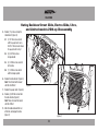
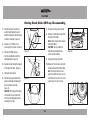
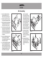
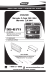
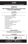
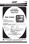
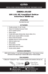
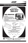
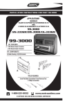
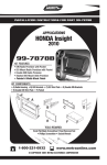
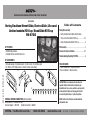
INSTALLATION INSTRUCTIONS FOR PART 99-9700
APPLICATIONS
Harley-Davidson Street Glide, Electra Glide, Ultra and
Limited models 2014-up / Road Glide 2015-up
99-9700
Table of Contents
Fairing Disassembly
–. Harley Davidson Street Glide, Electra Glide,
Ultra, and Limited models 2014-up....................2-3
–. Harley Davidson Road Glide 2015-up.................... 4
Kit Assembly........................................................... 5
KIT FEATURES
• ISO DIN radio provision
• Included interface and LCD info screen
Axxess interface installation...............................6-7
Troubleshooting/Updating 99-9700....................... 8
KIT COMPONENTS
• A) Radio housing • B) Radio brackets • C) LCD screen • D) LCD back plate
• E) (10) #8 x 3/8” Phillips screws • Axxess interface (not shown)
REV. 4/23/2015 INST99-9700
A
B
C
CAUTION: Metra recommends disconnecting the
negative battery terminal before beginning any
installation. All accessories, switches, and especially
air bag indicator lights must be plugged in before
reconnecting the battery or cycling the ignition.
E
WIRING & ANTENNA CONNECTIONS (sold separately)
Wiring Harness: • Included interface
Antenna Adapter: • 40-EU10 Handle bar controls: • ASWC-1
METRA. The World’s best kits.™
D
TOOLS REQUIRED
• Panel removal tool • Phillips screwdriver
• Torx screwdrivers • Allen wrenches
1-800-221-0932
NOTE: Refer to the instructions included with the
aftermarket radio.
metraonline.com
© COPYRIGHT 2015 METRA ELECTRONICS CORPORATION
99-9700
Harley Davidson Street Glide, Electra Glide, Ultra, and Limited models 2014-up
Disassembly
1. Remove (4) T-27 from inner fairing.
(Figure A)
2. Remove (3) T-27 from windshield
(caution not to drop the outer
fairing or windshield). (Figure B)
3. Remove outer fairing, unplugging
the headlight. (Figure C)
4. Remove (2) T-27 to remove the
fairing vent and remove the vent.
(Figure D)
Continued on next page
(Figure A)
(Figure C)
(Figure B)
(Figure D)
2
99-9700
5.
Harley Davidson Street Glide, Electra Glide, Ultra,
and Limited models 2014-up Disassembly
Remove (11) screws securing the
radio bracket: (Figure E)
5.1 (2) T-27 Torx screws shared
with the gauge cluster and a
third T-27 Torx screw to remove
the gauge cluster in step 7.
5.2 (4) 5/32” Allen screws
facing outward.
5.3 (4) T-25 Torx screws secured
to the radio.
5.4 (1) T-25 Torx screw shared
with the storage pocket.
6. Remove the radio bracket. (Figure E)
Note: This bracket will be reused
with the 99-9700 kit.
7. Remove the gauge cluster. (Figure E)
(Figure E)
8. Remove (4) 3/16 Allen screws from
the sides of radio. (Figure F)
Note: These screws will be reused
with the 9700 kit.
9. Slide the radio out toward the rear
of the bike, and unplug the radio.
(Figure F)
(Figure F)
3
99-9700
Harley Road Glide 2015-up Disassembly
7. Remove the fairing and set aside.
1. Remove the lower torx screws
on either side holding the wind
deflector wings (only the lower two
need to be removed). (Figure A)
8. Remove (4) 3/16 Allen screws from
the sides of the radio.
Note: These screws will be reused
with the 9700 kit.
CAUTION: Be sure to hold the
radio when removing the last
screw so it will not drop.
2. Remove (1) 3/16 Allen screw
securing each turn signal. (Figure B)
3. Remove (4) Phillips screws
from the windshield and set the
windshield aside. (Figure C)
(Figure A)
9. Unplug and remove the radio.
10.Remove (2) Torx screws securing the
fairing bracket attached to the radio.
Note: This bracket will be reused
with the 99-9700 kit. Please note the
orientation of the bracket. The curved
portion faces the rear of the bike.
4. Remove the top fairing trim clipped
to the top of the radio. (Figure D)
5. Unplug the turn signals.
6. Remove the speaker grills with a
panel removal tool and remove (1)
torx screw from each side.
(Figure E)
CAUTION: The fairing will be loose
at this point. Have a helper hold
it to keep from damaging it when
removing the screws.
(Figure D)
(Figure B)
(Figure C)
(Figure E)
4
99-9700
Kit Assembly
1. Secure the radio brackets to the
radio housing with (4) #8 x 3/8”
Phillips screws supplied. (Figure A)
2. Remove the metal “DIN” sleeve and
trim ring from the aftermarket radio.
3. Slide the radio into the radio housing
assembly and secure with screws
supplied with the radio. (Figure B)
4. Insert the LCD screen into the radio
housing, route the cable through the
LCD back plate, and then secure to
the radio housing assembly using (2)
#8 x 3/8” screws supplied with the
kit. (Figure C)
5. Secure the radio housing assembly
to the bike using (4) 3/16 Allen
screws previously removed in step 8
of disassembly. (Figure D)
6. (a) For the Street Glide, Electra Glide,
Ultra, and Limited models 2014-up;
Attach the radio bracket removed in
step 6 of disassembly to the top of the
radio housing assembly, and secure
with (4) Phillips screws supplied.
(b) For the Road Glide
2015-up; Attach the fairing
bracket removed in step 10
of disassembly to the top of
the radio housing assembly,
and secure with (2) Phillips
screws supplied. Ensure
the bracket is far forward,
and the curved portion is
facing the rear of the bike as
mentioned in disassembly.
7. Locate the factory wiring
harness and antenna plug
in the dash. Refer to the
interface wiring instructions
on pages 6-8.
8. Reassemble the fairing in
reverse order of disassembly,
and then pull the screen
protector off from the LCD
screen.
(Figure A)
(Figure C)
(Figure D)
(Figure B)
5
99-9700
Axxess Interface Installation
Connections to be made
FEATURES
• Provides accessory power (12-volt 10-amp)
From the 99-9700 harness to the aftermarket radio:
• High level speaker input
• Connect the Yellow wire to the battery wire.
• Retains balance and fade
• Connect the Red wire to the accessory wire.
• Retains oil pressure and EITMS status
• Connect the Orange wire to the illumination wire. (If the aftermarket radio
has no illumination wire, tape off the Orange wire).
• Prewired ASWC-1 harness included (ASWC-1 sold separately)
• Connect the White wire to the left front positive speaker output.
• Micro “B” USB updatable
• Connect the White/Black wire to the left front negative speaker output.
• Connect the Black wire to the ground wire.
• Connect the Gray wire to the right front positive speaker output.
• Connect the Gray/Black wire to the right front negative speaker output.
• Connect the Green wire to the left rear positive speaker output.
• Connect the Green/Black wire to the left rear negative speaker output.
INTERFACE COMPONENTS
• 99-9700 interface
• 99-9700 harness
• Connect the Purple wire to the right rear positive speaker output.
• Connect the Purple/Black wire to the right rear negative output
From the 12-pin pre-wired ASWC-1 harness to the aftermarket radio:
• This harness is to be used along with the optional ASWC-1 (not included) to
retain handlebar controls. If the ASWC-1 is not being used, disregard this
harness. If it will be used, please refer to the ASWC-1 instructions for radio
connections and programming.
TOOLS REQUIRED
• Cutting tool • Crimping tool • Tape
• Connectors (example: butt-connectors, bell caps, etc.)
Note: Disregard the harness that comes with the ASWC-1
6
99-9700
Installing the Interface
LCD Operation
With the key in the off position:
* The included LCD screen provides oil pressure and EITMS status.
• Connect the 99-9700 harness into the interface.
For more information, please see the owner’s manual that came with the bike.
• Connect the LCD screen into the interface.
Main menu options:
• Connect the 99-9700 harness into the vehicles wiring harness.
• Red adjusts the red backlighting of the LCD (ranges from 1 to 32).
• With all connections completed, reconnect the negative battery terminal.
• Blue adjusts the blue backlighting of the LCD (ranges from 1 to 32).
Note: To prevent error codes, all electronic devices including the headlight
and turn signals must be connected before proceeding to the next step.
• Green adjusts the green backlighting of the LCD (ranges from 1 to 32).
• Contrast adjusts the contrast of the LCD (ranges from 1 to 100).
• Reset puts the color back to the default settings.
Initializing the Interface
ATTENTION: If the interface loses power for any reason, the following step will need
to be performed again.
• Initialize the interface by turning the ignition on for 30-seconds, then turn the
ignition back off, then back on again.
Arrow Up - Toggles “up” through menu options
Arrow Down - Toggles “down” through menu options
Return/ESC - Return to the previous menu
Enter - Enter current menu option
Note: If using the ASWC-1, connect it after you initialize the interface, with the key in
the off position.
7
INSTALLATION INSTRUCTIONS FOR PART 99-9700
Troubleshooting
If the Oil/EITMS information do not show up on the kit, perform this step;
• Press and hold the “Return/ESC” button on the LCD screen for 5 seconds until “Select Interface” comes up.
• Select “Connection Type”, and then press “Enter”
• Scroll up or down to “Direct Connect”, and then press “Enter”
• Once done, press “Return/ESC” to back out of that mode.
REV. 4/23/2015 INST99-9700
Updating the 99-9700
• Download and install the WebXXpress software update from axxessinterfaces.com. Please follow
the instructions on the website exactly as stated.
• Connect the USB-MINI-CAB update cable (sold separately) between the 99-9700 and the computer.
• From the Start Menu of the computer, click on on “All Programs”, and then “USBBootloader”.
• Press “Update Board”, the software will begin to download at this point.
Note: Please note which firmware downloaded to the interface. This will help in troubleshooting,
if need be.
KNOWLEDGE IS POWER
Enhance your installation and fabrication skills by
enrolling in the most recognized and respected
mobile electronics school in our industry.
Log onto www.installerinstitute.com or call
800-354-6782 for more information and take steps
toward a better tomorrow.
Note: Both the interface AND display screen must be updated.
Metra recommends MECP
certified technicians
METRA. The World’s best kits.™
1-800-221-0932
metraonline.com
© COPYRIGHT 2015 METRA ELECTRONICS CORPORATION
Instrucciones de instalación para la pieza 99-9700
APLICACIONES
Harley-Davidson Street Glide, Electra Glide, Ultra y
Limited 2014 y masr recientes / Road Glide 2015 y
mas recientes 99-9700
Indice
Desmontaje Carenado
–. Harley Davidson Street Glide, Electra Glide,
Ultra, Modelos Limited 2014 y mas recientes.....2-3
–. Harley Davidson Road Glide 2015 y mas............... 4
Ensamble del kit..................................................... 5
Características del kit
• Provisión de radio ISO DIN
• Interfase y pantalla de información LCD incluidas
Instalación de la interfase Axxess......................6-7
Componentes del kit
• A) Carcasa del radio • B) Soportes del radio • C) Pantalla LCD • D) Placa posterior de LCD
• E) (10) tornillos Phillips #8 x 3/8” • Interfase Axxess (no se muestra)
REV. 4/23/2015 INST99-9700
A
B
C
E
CABLEADO Y CONEXIONES DE ANTENA (se venden por separado)
Arnés de cableado: • Interfase incluida
Adaptador de antena: • Controles de manubrio 40-EU10: • ASWC-1
METRA. The World’s best kits.™
1-800-221-0932
D
Resolución de problemas/
Actualización del 99-9700................................. 8
HERRAMIENTAS REQUERIDAS
• Herramienta para quitar paneles
• Destornillador Phillips
• Destornilladores Torx • Llaves Allen
PRECAUCIÓN: Metra recomienda desconectar el terminal
negativo de la batería antes de comenzar cualquier
instalación. Todos los accesorios, interruptores y,
especialmente, las luces indicadoras de airbag deben
estar enchufados antes de volver a conectar la batería o
comenzar el ciclo de ignición.
NOTA: Remítase a las instrucciones incluidas con el
radio de postventa.
metraonline.com
© COPYRIGHT 2015 METRA ELECTRONICS CORPORATION
99-9700
Harley Davidson Street Glide, Electra Glide, Ultra, modelos limited
2014 y mas recientes desensamble
1. Quite los (4) T-27 del carenado
interior. (Figura A)
2. Quite los (3) T-27 del parabrisas
(tenga cuidado de no dejar caer el
carenado exterior o el parabrisas).
(Figura B)
3. Quite el carenado exterior
desconectando el faro. (Figura C)
4. Quite los (2) T-27 para quitar la
rejilla del carenado y quite la rejilla.
(Figura D)
(Figura A)
(Figura C)
(Figura B)
(Figura D)
Continúa en la siguiente página.
2
99-9700
Harley Davidson Street Glide, Electra Glide, Ultra, modelos limited
2014 y mas recientes desensamble
5. Quite los (11) tornillos que sujetan
el soporte del radio: (Figura E)
5.1 (2) Tornillos Torx T-27 que se
comparten con el conjunto de
indicadores y un tercer tornillo
Torx T-27 para quitar el conjunto
de indicadores en el paso 7.
5.2 (4) Tornillos Allen de 5/32”
orientados hacia afuera.
5.3 (4) Tornillos Torx T-25
sujetados al radio
5.4 (1) Tornillos Torx T-25 que se
comparten con la cavidad de
almacenamiento.
6. Quite el soporte del radio. (Figura E)
Nota: Este soporte se volverá a
utilizar con el kit 99-9700.
7. Quite el conjunto de indicadores.
(Figura E)
8. Quite los (4) tornillos Allen de 3/16
(Figura E)
9. Deslice el radio hacia la parte
trasera de la motocicleta para
sacarlo y desconecte el radio.
(Figura F)
de los lados del radio. (Figura F)
Nota: Estos tornillos se volverán a
utilizar con el kit 9700.
(Figura F)
3
99-9700
Harley Road Glide 2015 y mas desensamble
7. Quite el carenado y déjelo a un lado.
1. Quite los tornillos Torx inferiores
de cada lado que sostienen los
deflectores de viento (solo deben
quitarse los dos inferiores). (Figura A)
2. Quite el (1) tornillo Allen de 3/16”
que sujeta cada señal direccional.
(Figura B)
8. Quite los (4) tornillos Allen de 3/16
de los lados del radio.
Nota: Estos tornillos se volverán a
utilizar con el kit 9700.
CAUTION: Asegúrese de sostener
el radio cuando se quite el último
tornillo para que no se caiga.
(Figura A)
3. Quite los (4) tornillos Phillips del
parabrisas y déjelo a un lado.
(Figura C)
(Figura D)
9. Desconecte y quite el radio.
10.Quite los (2) tornillos Torx que
sujetan el soporte del carenado
unido al radio.
Nota: Este soporte se volverá a
utilizar con el kit 99-9700. Tenga en
cuenta la orientación del soporte. La
parte curveada está orientada hacia
la parte trasera de la motocicleta.
4. Quite la moldura del carenado
superior enganchada en la parte
superior del radio. (Figura D)
5. Desconecte las señales direccionales.
(Figura B)
6. Quite las rejillas de las bocinas con
una herramienta de remoción de
panel y quite el (1) tornillo Torx de
cada lado. (Figura E)
PRECAUCIÓN: El carenado estará
suelto en este momento. Pida a
un ayudante que lo sostenga para
evitar dañarlo al quitar los tornillos.
(Figura C)
(Figura E)
4
99-9700
Kit Assembly
1. Sujete los soportes del radio
a la carcasa del radio con los
(4) tornillos Phillips #8 de 3/8”
suministrados. (Figura A)
2. Quite la manga de metal “DIN” y
el anillo de moldura del radio de
mercado secundario.
3. Deslice el radio en el ensamble de
la carcasa del radio y sujételo con
los tornillos suministrados con el
radio. (Figura B)
4. Inserte la pantalla LCD en la
carcasa del radio, enrute el cable
a través de la placa posterior del
LCD y luego sujételo al ensamble
de la carcasa del radio con los (2)
tornillos #8 de 3/8” suministrados
con el kit. (Figura C)
5. Sujete el ensamble de la carcasa
del radio a la motocicleta con los
(4) tornillos Allen de 3/16 que quitó
anteriormente en el paso 8 del
desensamble. (Figura D)
(Figura A)
(Figura B)
6. (a) Para los modelos Street Glide,
Electra Glide, Ultra y Limited 2014
y más recientes; coloque el soporte
del radio que quitó en el paso 6 del
desensamble en la parte superior
del ensamble de la carcasa del
radio y sujételo con (4) tornillos
Phillips suministrados.
(b) Para el Road Glide 2015 y más
recientes, coloque el soporte del
carenado que quitó en el paso 10 del
desensamble en la parte superior
del ensamble de la carcasa del radio
y sujételo con (2) tornillos Phillips
(Figura C)
suministrados. Asegúrese de que
el soporte esté lo más adelante
posible y la parte curveada esté
orientada hacia la parte trasera de la
motocicleta como se mencionó en el
desensamble.
7. Localice el arnés de cableado
de fábrica y el conector de la
antena en el tablero. Consulte las
instrucciones del cableado de la
interfase en las páginas 6-8.
8. Vuelva a armar el carenado al
revés de como lo desmontaje y , a
continuación, tire del protector de
la pantalla fuera de la pantalla LCD. (Figura D)
5
99-9700
Instalación de la interfase Axxess
Conexiones que se deben hacer
CARACTERÍSTICAS
• Provee corriente de accesorios (12 voltios 10 amperes)
Desde el arnés 99-9700 al radio de mercado secundario:
• Entrada de bocina de alto nivel
• Conecte el cable Amarillo con el cable de la batería.
• Retiene el balance y la intensidad
• Conecte el cable Rojo con el cable de accesorios.
• Retiene el estado de la presión del aceite y el EITMS
• Conecte el cable Anaranjado con el cable de iluminación. (Si el radio de mercado
secundario no tiene cable de iluminación, cubra con cinta el cable Anaranjado).
• Conecte el cable Negro con el cable de tierra.
• Arnés ASWC-1 pre cableado incluido (el ASWC-1 se vende por separado)
• Conecte el cable Blanco con la salida positiva de la bocina izquierda del frente.
• Actualizable por micro “B” USB
• Conecte el cable Blanco/Negro con la salida negativa de la bocina izquierda del frente.
• Conecte el cable Gris con la salida positiva de la bocina derecha del frente.
• Conecte el cable Gris/Negro con la salida negativa de la bocina derecha del frente.
• Conecte el cable Verde con la salida positiva de la bocina izquierda de atrás.
• Conecte el cable Verde/Negro con la salida negativa de la bocina izquierda de atrás.
COMPONENTES DE LA INTERFASE
• Interfase 99-9700
• Arnés 99-9700
• Conecte el cable Púrpura con la salida positiva de la bocina derecha de atrás.
• Conecte el cable Púrpura/Negro con la salida negativa de la bocina derecha de atrás.
Desde el arnés ASWC-1 pre cableado de 12 pins al radio de mercado secundario:
• Este arnés se debe usar junto con el ASWC-1 opcional (no incluido) para retener
los controles del manubrio. Si no se usará el ASWC-1, ignore este arnés. Si se
va a utilizar, consulte las instrucciones del ASWC-1 para las conexiones del
radio y la programación.
HERRAMIENTAS REQUERIDAS
• Corte • Herramienta que prensa de herramientas • Tape
• Conectores (ejemplo: a tope conectores, tapas de campana , etc.)
Nota: Ignore el arnés que viene con el ASWC-1.
6
99-9700
Instalación de la interfase
Operación de la pantalla LCD
Con la llave en la posición de apagado:
* La pantalla LCD incluida proporciona el estado de la presión de aceite y el EITMS.
• Conecte el arnés 99-9700 a la interfase.
• Conecte la pantalla LCD a la interfase.
Para más información, consulte el manual del propietario
que se incluye con la motocicleta.
• Conecte el arnés 99-9700 al arnés de cableado del vehículo.
Opciones del menú principal:
• Cuando todas las conexiones estén hechas, vuelva a conectar
la terminal negativa de la batería.
•
•
•
•
•
Nota: Para evitar códigos de error, todos los dispositivos electrónicos, incluyendo
los faro debe conectarse antes de continuar con el siguiente paso.
Rojo ajusta el color rojo de retroiluminación de la pantalla LCD (varía de 1 a 32).
Azul ajusta el color azul de retroiluminación de la pantalla LCD (varía de 1 a 32).
Verde ajusta el color verde de retroiluminación de la pantalla LCD (varía de 1 a 32).
Contraste ajusta el contraste de la pantalla LCD (varía de 1 a 100).
Restablecer regresa el color a los ajustes predeterminados.
Inicializar la interfase
Flecha arriba - Alterna hacia “arriba” entre las opciones del menú
ATENCIÓN: Si la interfase pierde energía por cualquier motivo, deberán realizarse los
siguientes pasos de nuevo.
Flecha abajo - Alterna hacia “abajo” entre las opciones del menú
Regresar/ESC - Regresa al menú anterior
• Para inicializar la interfase, encienda la marcha y espere 30 segundos, luego
vuelva a apagar la ignición, y enciéndala una vez más.
Aceptar - Ingresa a la opción actual del menú
Nota: Si va a usar el ASWC-1, conéctelo después de inicializar la interfase con
la llave en la posición de apagado.
7
Instrucciones de instalación para la pieza 99-9700
Resolución de problemas
Si la información del aceite/EITMS no aparece en el kit, realice este paso:
• Presione y mantenga presionado el botón “Regresar/ESC” en la pantalla LCD
durante 5 segundos hasta que aparezca “Seleccionar interfase”.
• Seleccione “Tipo de conexión” y luego presione “Aceptar”
• Desplácese hacia arriba o abajo hasta “Conexión directa” y luego presione “Aceptar”.
• Después de hacer esto, presione “Regresar/ESC” para salir de ese modo.
REV. 4/23/2015 INST99-9700
Actualización del 99-9700
•
•
•
•
Descargue e instale la actualización del software WebXXpress en axxessinterfaces.com.
Siga las instrucciones en el sitio web exactamente como se indican.
Conecte el cable de actualización USB-MINI-CAB (se vende por separado)
entre el 99-9700 y la computadora.
Desde el menú de inicio de la computadora, haga clic en “Todos los programas”
y luego en “USBBootloader”.
Presione “Actualizar tablero” y en este momento el software empezará a descargarse.
Nota: Anote qué firmware se está descargando a la interfase. Esto le ayudará en la resolución de
problemas, de ser necesario.
Nota: Tanto la interfase como la pantalla deben actualizarse.
METRA. The World’s best kits.™
1-800-221-0932
metraonline.com
EL CONOCIMIENTO ES PODER
sus habilidades deIS
instalación
y
KMejore
NOWLEDGE
POWER
Enhance
your installation
and fabrication
skills by
fabricación
inscribiéndose
en la escuela
de
enrolling in the most recognized and respected
dispositivos electrónicos móviles más reconocida
mobile electronics school in our industry.
y respetada
de nuestra industria.
en
Log
onto www.installerinstitute.com
or Regístrese
call
800-354-6782
for more information
and take
www.installerinstitute.com
o llame
al steps
toward a better tomorrow.
800-354-6782 para obtener más información y
avance hacia un futuro mejor.
Metra recomienda técnicos
con certificación del Programa
de Certificación en Electrónica
Móvil (Mobile Electronics
Certification Program, MECP).
© COPYRIGHT 2015 METRA ELECTRONICS CORPORATION