1
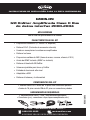
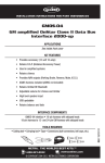
INSTALLATION INSTRUCTIONS FOR PART INSTGMOS-09
GMOS-09
GM amplified OnStar Class II Data Bus
Interface 2000-2004
APPLICATIONS
See inside front cover
KIT FEATURES
• Providesaccessory(12-volt10-amp)
• RetainsR.A.P.(RetainedAccessoryPower)
• Usedinamplifiedsystems
• Retainschimes
• ProvidesNAVoutputs(parkingbrake,reverse,mute,V.S.S.)
• ASWCharnessincluded(ASWCnotincluded)
• RetainsOnStar/OEBluetooth
• AdjustablevolumeforchimesandOnStar
• Highlevelspeakerinput
• USBupdatable
• Retainsbalanceandfade
INTERFACE COMPONENTS
TOOLS REQUIRED
CuttingTool•CrimpingTool•Tape•Connectors(example:butt-connectors,bellcaps,etc.
ISO
M4
M3.5
IGNITION
TERMINALS
M2.6
M3
6
2.5
WIRE
CUTTER
1.5
M5
METRA. THE WORLD’S BEST KITS.™
metraonline.com
1-800-221-0932
© COPYRIGHT 2004-2011 METRA ELECTRONICS CORPORATION
REV. 12/21/11
•GMOS-09interface•16-pinharnesswithstrippedleads
•18-pinharnessto32-pinGMharnesswithstrippedleads
GMOS-09
Applications
(Note: This interface will also work in vehicles listed below that are not equipped with OnStar)
OLDSMOBILE
Aurora
2001-2003
PONTIAC
Bonneville
2000-2004
Caution: Metra recommends disconnecting the negative battery terminal before beginning
any installation. All accessories, switches, and especially air bag indicator lights must be
plugged in before reconnecting the battery or cycling the ignition.
*NOTE: Refer also to the instructions included with the aftermarket radio.
GMOS-09
Connections to be made
From the 16-pin harness:
• ConnecttheRedwiretotheignitionwireoftheaftermarketradio
• ConnecttheOrange/Whitewiretotheilluminationwireoftheaftermarketradio.Ifthe
aftermarketradiohasnoilluminationwirejusttapeofftheOrange/Whitewire.
• ConnecttheWhitewiretotheleftfrontpositivespeakeroutputoftheaftermarketradio
• ConnecttheWhite/Blackwiretotheleftfrontnegativespeakeroutputofthe
aftermarketradio
• ConnecttheGraywiretotherightfrontpositivespeakeroutputoftheaftermarketradio
• ConnecttheGray/Blackwiretotherightfrontnegativespeakeroutputofthe
aftermarketradio
• ConnecttheGreenwiretotheradio’sleftrearpositivespeakeroutput.
• ConnecttheGreen/Blackwiretotheradio’sleftrearnegativespeakeroutput.
• ConnectthePurplewiretotheradio’srightrearpositivespeakeroutput.
• ConnectthePurple/Blackwiretotheradio’srightrearnegativespeakeroutput.
• ConnecttheBlue/Whitewiretotheradio’sampturnonwire
• ConnecttheBrownwiretothemutewireoftheaftermarketradio.Iftheaftermarket
radiodoesnothaveaMutewire,tapeuptheBrownwire.
• ConnecttheLight Greenwiretotheparkingbrakewireoftheaftermarket
navigationradio.
• ConnecttheBlue/PinkwiretotheVSSorspeedsensewireoftheaftermarket
navigationradio.
• ConnecttheGreen/Purplewiretothereversewireoftheaftermarketnavigationradio.
• Plugthe16-pinharnessintotheGMOS-09
3
GMOS-09
Connections to be made
From the 32-pin harness:
• ConnecttheYellow wiretotheradio’s12-voltbatteryormemorywire.
• ConnecttheBlackwiretotheradio’sgroundwire.
• Plugthe14-pinharnessintotheGMOS-09
• TheBlack/YellowwireisfortheOnStarvolumeadjustment.Thiswillbediscussedin
theOnStarLevelAdjustmentsectionofthisinstruction.
Installing the GMOS-09
• Withallconnectionscompletedtotheaftermarketradio,plugthe24-and12-pin
harnessesintothevehicleswiringharnesses.
• Reconnectthenegativebatteryterminal.
• Cyclethekey,byturningtheignitiononfor30seconds.Thenoffandon
againtotesttheradio.
Testing the GMOS-09
1) Turntheignitiononifnotalready,andthenturntheradioontoverifythattheradio
works.Checkbalanceandfadercontrolsforproperoperation.
2) PushtheOnStarbutton(ifequipped)toverifyOnStarisworking.Theradiowillshutoffor
mute,dependingiftheBrownwireonthe16-pinharnessisconnected,andOnStarwill
beheardthroughthefrontspeakers.TurnoffOnStarandtheradiowillturnbackon.
Continued on next page
4
GMOS-09
Chime Volume Adjustment
Note: If Y91 is present on the RPO list, refer to
your owner’s manual to adjust chimes.
1) Withcaron,shutoffcarandleavekeys
inignition.Openthecardoorandleaveit
open.Chimeswillbeheard.
2) Wait10seconds,thenwithasmall
screwdriveradjustthepotentiometer
fullycounterclockwise(allthewayleft),
thenclockwisetoraisechimeleveland
counterclockwisetolowerthechimelevel.
3) Whenthevolumeisatthedesiredlevel,
removethekeysfromtheignition.Thiswill
lockthechimevolumeatitscurrentlevel.
Potentiometer located on the 16 pin side
of the interface
Audio Level Adjustment
1) Startyourvehicleandturnontheradiohavingaudioplaying.
2) Turnyouraftermarketradio’svolumeup¾oftheway.
3) Withasmallscrewdriveradjustthepotentiometerclockwisetoraisetheaudioleveland
counterclockwisetolowertheaudiolevel.
4) Onceatdesiredlevelyouraudioadjustmentiscomplete.
OnStar Level Adjustment
ToadjusttheOnStarvolumelevelfindtheBlack/Yellowwireonthe16-pinharness.Push
theblueOnStarbutton,whilethevoiceisspeakingtaptheBlack/Yellowwiretoground.
Thereare4volumesettingsforOnStar;oncethe4thsettingisreachedandtheBlack/
Yellowwireistappedtogrounditwillautomaticallygobacktothefirstvolumesetting.
OncethevolumeissetitwillstayatthatvolumeuntiltheBlack/Yellowwireistappedto
groundagain.Thiscanbesetduringinstallationandthenleftalone.Ifuseradjustmentis
desired,thecustomermayalsotapvolumeupordownonthesteeringwheel(ifequipped)
toadjusttheOnStarlevel.
5
Notes
Notes
INSTALLATION INSTRUCTIONS FOR PART INSTGMOS-09
IMPORTANT WARNING
Thisproductincludesinstructionsforinstallationwhichmustbecarefullyfollowed.The
instructionsarewordedinsuchamannertoassumethattheinstalleriscapableof
completingthesetypeofelectronicinstallations.Ifyouareunclearastowhatyouare
instructedtodoorbelievethatyoudonotunderstandtheinstructionssoastoproperly
andsafelycompletetheinstallationyou should consult a technician who does have this
knowledge and understanding.
Failure to follow these instructions carefully and to install the interface as described
could cause harm to the vehicle or to safety systems on the vehicle. Interference
with certain safety systems could cause harm to persons as well. If you have any
questions in this regard please call the Help line or Metra at
1-800-221-0932 for assistance.
KNOWLEDGE IS POWER
Enhance your installation and fabrication skills by
enrolling in the most recognized and respected
mobile electronics school in our industry.
Log onto www.installerinstitute.com or call
800-354-6782 for more information and take steps
toward a better tomorrow.
REV. 12/21/11
Metra recommends MECP
certified technicians
METRA. THE WORLD’S BEST KITS.™
metraonline.com
1-800-221-0932
© COPYRIGHT 2004-2011 METRA ELECTRONICS CORPORATION
INSTRUCCIONES DE INSTALACIÓN PARA LA PIEZA INSTGMOS-09
GMOS-09
GM OnStar Amplificada Clase II Bus
de datos interfaz 2000-2004
APLICACIONES
Vea la lista de aplicaciones en el interior
CARACTERÍSTICAS DEL KIT
• Proporcionaaccesorio(12voltios10amperes)
• RetieneR.A.P.(Corrientedeaccesorioretenida)
• Usadoenreemplazanlossistemasamplificados
• Retienelostonos
• ProporcionasalidasdeNAV(frenodemano,reversa,silencio,V.S.S.)
• ArnésdeASWCincluido(ASWCnoincluido)
• RetieneelbluetoothOE/OnStar
• VolumenajustableparatonosyOnStar
• Entradadebocinadealtonivel
• AdaptableaUSB
• Retieneelbalanceylaintensidad
COMPONENTES DEL KIT
•InterfazGMOS-09•Arnésde16pinesconconectorespelados
•Arnésde18pinsaarnésGMde32pinsconconectorespelados
ISO
M4
M3.5
IGNITION
TERMINALS
M2.6
M3
6
2.5
WIRE
CUTTER
1.5
M5
METRA. THE WORLD’S BEST KITS.™
metraonline.com
1-800-221-0932
© COPYRIGHT 2004-2011 METRA ELECTRONICS CORPORATION
REV. 5/30/12
HERRAMIENTAS REQUERIDAS
•Herramientadecorte•Cinta•Herramientaengarzadora
•Conectores(p.ej.,conectoresatope,tapasacampanadas,etc.)
GMOS-09
Aplicaciones
(Nota: Esta interfaz también funcionará en los vehículos enumerados a continuación
que no están equipados con OnStar)
OLDSMOBILE
Aurora
2001-2003
PONTIAC
Bonneville
2000-2004
PRECAUCIÓN: Metra recomienda desconectar el terminal negativo de la batería antes de
comenzar cualquier instalación. Todos los accesorios, interruptores y, especialmente, las
luces indicadoras de airbag deben estar enchufados antes de volver a conectar la batería o
comenzar el ciclo de ignición.
Nota: Remítase a las instrucciones incluidas con el radio de postventa.
GMOS-09
Conexiones que se deben hacer
Desde el arnés de 16 pins:
• ConecteloscablesRojoconelcabledeignicióndelradiodemercadosecundario.
• ConecteelcableAnaranjado/Blancoconelcabledeiluminacióndelradiodemercado
secundario.Sielradiodemercadosecundarionotienecabledeiluminaciónsolocubra
concintaelalambreanaranjado.
• ConecteelcableBlancoconlasalidadelabocinapositivafrontalizquierdadelradiode
mercadosecundario.
• ConecteelcableBlanco/Negroconlasalidadelabocinanegativafrontalizquierdadel
radiodemercadosecundario.
• ConecteelcableGrisconlasalidadelabocinapositivafrontalderechadelradiode
mercadosecundario.
• ConecteelcableGris/Negroconlasalidadelabocinanegativafrontalderechadel
radiodemercadosecundario.
• ConecteelcableVerde conlasalidadelabocinapositivaizquierdadeatrásdelradio.
• ConecteelcableVerde/Negroconlasalidadelabocinanegativaizquierdade
atrásdelradio.
• ConecteelcablePúrpuraconlasalidadelabocinapositivaderechadeatrásdelradio.
• ConecteelcablePúrpura/Negroconlasalidadelabocinanegativaderecha
deatrásdelradio.
• ConecteelcableAzul/Blancoconelcabledeencendidodelamplificador.
• ConecteelcableCaféconelcabledesilenciodelradiodemercadosecundario.Siel
radiodemercadosecundarionotieneuncabledeSilencio,encinteelcableCafé.
• ConecteelcableVerde claroconelcabledelfrenodemanodelradiodemercado
secundario.
• ConecteelcableAzul/RosaconelcableVSSodedeteccióndevelocidaddelradiode
navegacióndemercadosecundario.
• ConecteelcableVerde/Púrpuraconelcabledelareversadelradiode mercadosecundario.
• Conecteelarnésde16pinsenelGMOS-09.
3
GMOS-09
Conexiones que se deben hacer
Desde el arnés GM de 32 pins:
• ConecteelcableAmarilloconlabateríade12voltiosoelcabledememoriadelradio.
• ConecteelcableNegroconelcabledepuestaatierradelradio.
• Conecteelarnésde14pinsenelGMOS-09
• ElcableNegro/AmarilloesparaelajustedevolumendeOnStar.
EstoseexplicaráenlasecciónAjustedelniveldeOnStardeesteinstructivo.
Instalación del GMOS-09
• Contodaslasconexionesrealizadasalaradionooriginal,conectelos24y12pines
enlosarnesesdelosarnesesdecableadovehículos.
• Vuelvaaconectarelterminalnegativodelabatería.
• Ciclodelallave,girandolallavedeencendidodurante30segundos.Acontinuación,
apagueyvuelvaaponerapruebalaradio.
Prueba del GMOS-09
1) Prendalaigniciónsinolohahecho,ydespuésprendaelradioparaprobarsifunciona.
Revisequefuncionenbienloscontrolesdebalanceeintensidad.
2) PresioneelbotóndeOnStar(silotiene)paraverificarqueOnStarestéfuncionando.El
radioseapagaráosepondráensilencio,dependiendodesielcable Cafédelarnésde
16pinsestáconectado,yseescucharáOnStarporlasbocinasfrontales.ApagueOnStar
yelradiosevolveráaprender.
Continúa en la página
4
GMOS-09
Ajuste del volumen de los tonos
Nota: Si Y91 está presente en la lista de
RPO, consulte el manual del propietario para
ajustar campanillas.
1) Conelcocheencendido,apagadocoche
ydejarlasllavesenlaignición.Abrala
puertadelcocheydejarloabierto.Chimes
seráescuchado.
2) Espere10segundos,yluegoconun
destornilladorpequeñoparagirarel
potenciómetrototalmentehaciala
izquierda(todoelcaminoalaizquierda),
yluegohacialaderechaparaaumentarla
campanadayhacialaizquierdaparabajar
elniveldeltimbre.
Potenciómetro situado en el lado de 16 pines
de la interfaz
3) Cuandoelvolumenestáenelnivel
deseado,retirelasllavesdelcontacto.Esto
bloquearáelvolumendeltimbreensunivelactual.
Ajuste del nivel de audio
1) Iniciesuvehículoyenciendalaradioconreproduccióndeaudio.
2) Enciendaelvolumendesuradionooriginaldehastatrescuartaspartesdelaforma.
3) Conundestornilladorpequeñoparagirarelpotenciómetrohacialaderechaparaelevar
elniveldeaudioylaizquierdaparabajarelniveldeaudio.
4) Unavezenelniveldeseadopuedeajustarelaudiocompleto.
Ajuste del nivel de OnStar
ParaajustarelniveldeOnStar,encuentreelcableNegro/Amarilloenelarnésde16pins.
PresioneelbotónOnStar,mientrasseoyelavoz,conecteelcableNegro/Amarilloatierra.
Hay4ajustesdevolumenparaOnStar;unavezquellegueal4oajusteyelcableNegro/
Amarillosetoqueatierra,automáticamenteregresaráalprimerajustedevolumen.Una
vezqueelvolumenestéajustadosequedaráenesevolumenhastaqueelcableNegro/
Amarillosetoqueatierradenuevo.Estopuedeajustarsedurantelainstalaciónyluego
novolveracambiarse.Sisedeseaqueelusuariopuedahacerajustes,elclientetambién
puedepulsarelbotónquesubeobajaelvolumendesdeelvolante(siestáequipado)para
ajustarelniveldeOnStar.
5
Notas
Notas
INSTRUCCIONES DE INSTALACIÓN PARA LA PIEZA INSTGMOS-09
ADVERTENCIA IMPORTANTE
Esteproductoincluyeinstruccionesdeinstalaciónquedebenseguirse
cuidadosamente.Dichasinstruccionesestánredactadasdandopor
supuestoqueelinstaladorescapazdecompletarestostiposde
instalacioneselectrónicas.Sitienedudasrespectodeloquesele
indicaquehagaocreequenocomprendelasinstruccionescomopara
completarlainstalaciónenformaadecuadaysegura,debeconsultara
untécnicoqueefectivamentetengaestosconocimientosycomprensión.
Si no sigue estas instrucciones con cuidado y no instala la
interfaz como se describe, podría provocar daños en el vehículo
o en los sistemas de seguridad del vehículo. La interferencia con
determinados sistemas de seguridad también podría provocar
daños a las personas. Si tiene alguna pregunta al respecto, llame
a la línea de ayuda o a metra, al 1-800-221-0932 para obtener
asistencia.
EL CONOCIMIENTO ES PODER
KNOWLEDGE
IS POWER
Mejoresushabilidadesdeinstalaciónyfabricación
Enhance your installation and fabrication skills by
inscribiéndoseenlaescueladedispositivos
enrolling
in the most recognized and respected
mobile
electronics school in our industry.
electrónicosmóvilesmásreconocidayrespetadade
Log onto www.installerinstitute.com or call
nuestraindustria.Regístreseenwww.installerinstitute.
800-354-6782
for more information and take steps
toward
a better tomorrow.
comollameal800-354-6782paraobtenermás
informaciónyavancehaciaunfuturomejor.
REV. 5/30/12
Metra recomienda técnicos con
certificación del Programa de
Certificación en Electrónica Móvil
(Mobile Electronics Certification
Program, MECP).
METRA. THE WORLD’S BEST KITS.™
metraonline.com
1-800-221-0932
© COPYRIGHT 2004-2011 METRA ELECTRONICS CORPORATION