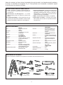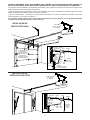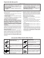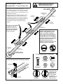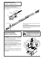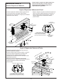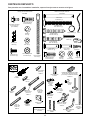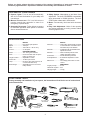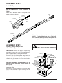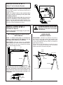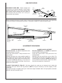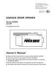
1
The Chamberlain Group, Inc.
A DUCHOSSOIS ENTERPRISE
845 Larch Avenue
Elmhurst, Illinois 60126
Manual del Propietario
Abre puerta para Puerta de Garaje
SOLO PARA USO RESIDENCIAL
Modelo 701-2E — 1/2 HP
ATENCION! FAVOR DE LEER ESTE MANUAL CUIDADOSAMENTE
La etiqueta con el número de modelo de su abre puerta está en el panel delantero.
CONTENIDO
PAGINA
Reglas de Seguridad ...........................................................2
Características del Abre Puerta ..........................................3
Especificaciones ..................................................................3
Herramientas Necesarias....................................................3
Illustraciones del Abre puerta Ensamblado e Instalado....4
Operación del Abre Puerta..................................................5
Accesorios............................................................................5
Programa de Mantenimiento...............................................6
Ensamblado .........................................................................7
Información para la Instalación......................................10
Ajuste de Límite .................................................................20
CONTENIDO
PAGINA
Ajuste de Sensibilidad...........................................................21
Prueba de Seguridad en Reversa........................................22
El Sistema Fotocelda .........................................................22
Las Instrucciones para Programar de Código.....................23
¿Hay Algún Problemas?.......................................................24
Lista de Empaque .................................................................26
Componentes de Repuesto del Riel ....................................26
Componentes de Repuesto, Instalación..............................26
Componentes de Repuesto, Cabeza ..................................27
Como Pedir Repuestos ........................................................28
Garantía.................................................................................28
GUARDAR ESTE MANUAL CERCA DE LA PUERTA DEL GARAJE.
ES NECESARIO EFECTUAR REVISIONES PERIODICOS PARA OBTENER UNA OPERACION SATISFACTORIA.
COMIENCE POR LEER ESTAS REGLAS DE SEGURIDAD
ESTOS SÍMBOLOS SIGNIFICAN ALERTA Y PRECAUCIÓN – SEGURIDAD PERSONAL, DAÑOS A SU
PROPIEDAD O PELIGRO ELÉCTRICO. LÉALO CON TODO CUIDADO.
ESTE OPERADOR DE GARAJE HA SIDO DISEÑADO Y PROBADO PARA PROPORCIONAR SERVICIO
RAZONABLEMENTE SEGURO SIEMPRE QUE SU INSTALACION Y OPERACION ESTE EN ESTRICTO
ACUERDO A LAS INSTRUCCIONES DE SEGURIDAD SIGUIENTES.
LA NEGLIGENCIA PARA OBEDECER ESTAS INSTRUCCIONES PUEDE RESULTAR EN LESIONES
PERSONALES SERIAS O EN DAÑOS A SU PROPIEDAD.
PRECAUCION: SI SU GARAGE NO TIENE PUERTA DE ENTRADA DE SERVICIO. INSTALE LA CERRADURA
PARA ABERTURA DE EMERGENCIA MODELO 7702CB. ESTE ACCESORIO PERMITE LA OPERACION MANUAL
DE LA PUERTA DEL GARAGE DESDE EL EXTERIOR EN CASO DE HABER UN CORTE DE ENERGIA ECTRICA.
MANTENGA LA PUERTA DE SU GARAJE
BALANCEADA. Una puerta que se atora o se
pega debe ser reparada. La puerta, los
resortes, cables y poleas y demás herrajes
están bajo tensión extrema y pueden causar
lesiones personales serias. NO TRATE DE
AFLOJAR, MOVER O AJUSTARLAS. Llame
al técnico especialista.
NO HAGA USO DE LOS AJUSTES DE
FUERZA PARA COMPENSAR POR UNA
PUERTA QUE SE PEGA O ATORA. La
fuerza excesiva interfiere con la operación del
sistema de seguridad en reversa o puede
dañar la puerta misma (página 21).
Fije la etiqueta de PRECAUCION en la pared,
junto al panel, para recordarle los procedimientos de seguridad.
NO USE ANILLOS, RELOJ PULSERA O
ROPA AMPLIA durante la instalación o
reparación de una puerta de garaje.
ABRA TODAS LAS CERRADURAS DE LA
PUERTA para evitar dañar la misma.
Para evitar daños personales QUITE LOS
LAZOS AMARRADOS A LA PUERTA
antes de proceder a su instalación.
Instale el botón iluminado (u otros adicionales)
EN UN LUGAR DONDE LA PUERTA DE LA
COCHERA ESTE A LA VISTA, PERO
FUERA DEL ALCANCE DE LOS NIÑOS. NO
PERMITA QUE LOS NIÑOS OPEREN LOS
CONTROLES DE PARED NI EL TRANSMISOR. Serias lesiones personales pueden
resultar por mal uso del abre puerta.
La instalación y alambrado eléctrico habrá de
reunir las especificaciones de construcción y
eléctricas de su localidad. CONECTE LOS
CABLES ELECTRICOS SOLO A UN TOMACORRIENTE PROPIAMENTE ATERRIZADO.
PRECAUCION: Active el abre puerta sólo
cuando la puerta esté completa a la vista,
libre de obstrucciones y el abre puerta
propiamente ajustado. NADIE DEBE
ENTRAR O SALIR DE LA GARAJE
ESTANDO LA PUERTA EN MOVIMIENTO.
NO PERMITA QUE LOS NIÑOS JUEGUEN
EN SU PROXIMIDAD.
ALGUNAS PUERTAS DE LAMINA,
ALUMINIO O FIBRA DE VIDRIO TENDRAN
QUE SER REFORZADAS SUBSTANCIALMENTE PARA EVITAR DAÑOS A LAS
MISMAS. (Vease la página 17.) La solución es
consultar con el fabricante de la puerta y
ordenar un juego de refuerzo.
Use la manija de emergencia SOLO para
liberar el carro y si es posible solo cuando la
puerta esté cerrada. NO USE LA MANIJA DE
EMERGENCIA PARA TRATAR DE ABRIR O
CERRAR LA PUERTA.
LA PRUEBA DE SEGURIDAD DEL
SISTEMA DE REVERSA ES MUY
IMPORTANTE (página 22). La puerta de su
garaje debe dar reversa al encontrar un
obstáculo de 1 pulgada colocado en el
piso. Si los ajustes del operador no se
hacen cuidadosamente pueden causar
lesiones personales serias causadas por la
puerta en descenso. REPITA ESTA
PRUEBA UNA VEZ AL MES Y HAGA LOS
AJUSTES NECESARIOS.
DESCONECTE LA CORRIENTE ELECTRICA
AL ABRE PUERTA ANTES DE HACER
REPARACIONES O QUITAR LAS MICAS.
2
Antes de comenzar, por favor revise el contenido de la caja de cartón. Las ilustraciones de las piezas y
el herraje, se muestran en las páginas 26 y 27. Para proceder con el ensamble e instalación, separe
el herraje como se muestra en la figura.
CARACTERISTICAS DEL ABRE PUERTA
1. Luces: Encienden y apagan automáticamente con
4-1/2 minutos de iluminación para seguridad y
conveniencia.
2. Desconexión de Emergencia: El cordón
desconectador permite la operacion manual de la
puerta.
3. Conexión Automática: Las dos partes del carro se
conectan para operación automática cuando el abre
puertas es energizado, después de una emergencia.
4. Sistema de Seguridad: Ajustes independientes de
fuerza hacia arriba y hacia abajo. La puerta dá
REVERSA automáticamente cuando se obstruye el
DESCENSO. La puerta para automáticamente
cuando se obstruye el ASCENSO.
5. Motor: Permanéntemente lubricado, con capacitor.
6. Ajuste Fácil de Límites: Los límites de la puerta,
tanto al abrir como al cerrar, son ajustes de tornillo y
sin quitar mica.
ESPECIFICACIONES
SEGURIDAD
Personal......................................Reversa automática y por
botón en descenso. Paro
automático y por botón en
ascenso.
Electrónico..................................Ajustes independientes de
sensibilidad.
Eléctrico ......................................Protector de sobrecarga para
el motor. Controles de voltaje
bajo.
Dispositivo de Límite..................El circuito se controla por
sistema de interruptor de
paro.
Ajuste de Límites........................Ajuste de tornillo en el panel
lateral.
Circuito de Arranque ..................Controles de botón y radio a
bajo voltaje.
DIMENSIONES
Largo (total) ................................3.15m
Espacio libre al techo.................5cm
Peso total....................................14.5 kg
MOTOR
Tipo .............................................Capacitor permanente
dividido.
Velocidad....................................1500 rpm.
Voltios .........................................120 Voltios CA - 60 ciclos.
Unicamente.
Corriente .....................................4.5 Amperes.
TRANSMISION
Engranes ....................................Sinfin reductor 16:1.
Sistema.......................................Cadena y cable con carro de
1 parte en riel de acero
forma "T".
Longitud de Carrera ...................Ajustable a 2.29m.
Velocidad....................................De 15 a 20 cm/s por
segundo.
Lámparas....................................Encienden cuando la puerta
se acciona; se apagan 4-1/2
minutos después de cerrar.
Conexiones de la puerta ..............Brazo ajustable. Cordón
liberador del carro.
HERRAMIENTAS DE MANO
Durante el ensamblado e instalación de su operador se necesitarán varias herramientas de mano.
Lápiz
Nivel de
carpintero
2
1
Segueta
Cinta de medir
Corta cables
Taladro
Escalerilla
Brocas de 5mm,
8mm, y 4mm
Llave y casquillos
de 13mm y 11mm
Martillo
Alicates
Destornillador
3
Llave de extremo ajustable
ANTES DE PROCEDER, POR FAVOR EXAMINE CON CUIDADO LAS ILUSTRACIONES DONDE ENSEÑAN LA
INSTALACION NORMAL DE UN ABRE PUERTA DE GARAJE DE PUERTAS SECCIONALES Y DE UNA PIEZA.
Las instrucciones de instalación para puertas seccionales y para puertas de una pieza son diferentes. Siga solo las
instrucciones para el tipo de puerta que usted tiene.
¿Tiene su garaje las vigas cubiertas y está el techo acabado? Si es cierto, necesitará un sostén de soporte y herraje
adicional. Se especifican estos puntos en el Paso 5, Página 14.
¿Tiene una puerta ligera, o de aluminio (o tiene paneles de vidrio)? Si es cierto, refuerzos horizontales y verticales
serán necesarios. Ver el Paso 10, Página 17.
Si es posible instale el abre puerta 7 pies o más de distancia por encima del piso, con la manija del liberador
manual del carro montada 6 pies por encima del piso.
INSTALACION DE
PUERTA SECCIONAL
Sostén de
soporte y tornilleria
(no incluidos)
Sporte de
cabecera
Cuerda
Polea final
Carro
Se necesitan refuerzos
horizontales y
verticales con puertas
de fibra de vidrio,
aluminio ligero,
metal ligero o puertas
con paneles de vidrio.
Cadena
Los
resortes
Refuerzo
horizontal
de puerta
(si necesario)
Cabecera
Puerta
Brazo
recto
Brazo
curvo
Liberador
del carro
manual y manija
Sostén de
la puerta
Refuerzo vertical de
puerta (si necesario)
INSTALACION DE
PUERTA DE UNA PIEZA
Sostén de soporte
y tornilleria
(no incluidos)
Polea final
Cuerda
Carro
Cadena
Sporte de
cabecera
Sostén de
la puerta
Brazo
recto
Cabecera
4
Puerta
Brazo
curvo
Liberador
del carro
manual
y manija
Operación del abre puerta
PRECAUCION
• PARA EVITAR DIFICULTADES DURANTE LA INSTALACION, NO OPERE EL ABRE PUERTA HASTA QUE
RECIBA INSTRUCCIONES DE HACERLO.
• NO ACTIVE EL ABRE PUERTA HASTA QUE ESTE
DEBIDAMENTE AJUSTADO, CON LA PUERTA A LA
VISTA Y SIN OBSTRUCCIONES.
• ANTES DE PROCEDER, LEA POR FAVOR LAS
REGLAS DE SEGURIDAD EN LA PAGINA 2 Y LAS
INSTRUCCIONES DE OPERACION EN ESTA PAGINA
CON TODO CUIDADO.
• NO PERMITA QUE LOS NIÑOS JUEGUEN CERCA DE
LA PUERTA.
LA LUZ DEL ABRE PUERTA se encenderá bajo las
siguientes condiciones: cuando el operador se conecta
inicialmente; cuando la corriente eléctrica se interrumpe;
cuando el abre puerta ha sido activado. Esta se apagará
automáticamente después de 4-1/2 minutos. Un foco de 75
watts es el máximo que debe usarse.
CUANDO SE ACTIVA EL OPERADOR:
1. Si está abierta. La puerta cerrará. Si está cerrada la
puerta abrirá.
2. Si está cerrando, la puerta dará reversa.
3. Si está abriendo, la puerta parará (dejando espacio para
entrada y salida de animales caseros y de aire fresco).
4. Si la puerta ha sido detenida parcialmente abierta, esta
cerrará.
5. Si al estar cerrando la puerta encuentra un obstáculo, la
puerta dará reversa.
6. Si al estar abriendo la puerta encuentra un obstáculo, la
puerta se detendrá.
7. El Sistema Fotocelda opcional usa un rayo invisible que
cuando es interrumpido al momento que la puerta se está
cerrando ocasiona que la puerta se regrese y si la puerta
estaba abierta no cerrará mientras se obstruya el paso
del rayo. Es muy recomendable para uso residencial para
evitar accidentes a niños.
USO DEL abre puerta
Su abre puerta puede ser activado por cualquiera de los
siguientes controles:
1. El Transmisor de un solo canal. Oprima el botón hasta
que la puerta empiece a moverse.
2. El Botón Iluminado. Oprima la tecla hasta que la puerta
empiece a moverse.
3. La Llave de Emergencia o el Transmisor de Código
(si ha instalado cualquiera de estos accesorios).
ABRIENDO LA PUERTA MANUALMENTE
LA PUERTA DEBE ESTAR TOTALMENTE CERRADA SI
ES POSIBLE. LOS RESORTES DEBILES O ROTOS
PUEDEN OCASIONAR QUE LA PUERTA CAIGA
RAPIDAMENTE. DAÑOS A SU PROPIEDAD O A SU
PERSONA PUEDEN RESULTAR. NO TRATE DE ABRIR
O CERRAR LA PUERTA POR MEDIO DE LA MANIJA DE
EMERGENCIA.
La puerta puede abrirse manualmente desconectándola del
operador. Jale con firmeza la manija de color rojo para
desconectar y luego puede ya abrir la puerta con la mano.
Para reconectar automáticamente la puerta al abre puerta,
oprima el botón iluminado.
OPERACION MANUAL TEMPORAL: No permite la
reconexión automática del carro. Si quiere dejar le
puerta en operación manual, jale le manija del cordón
liberador de carro hacia abajo y corra el carro hacia el
abre puerta. El carro permanecerá sin enganchar y la
puerta podra abrirse o cerrarse manualmente. Para
reconectar el carro, jale la manija del cordón directo
hacia abajo.
Accesorios Útiles Para Su Abre Puerta
Modelo 853CB
TRANSMISOR EXTRA:
Tamaño normal. Incluye sujetador.
Modelo 760E
SISTEMA DIGITAL:
Permite que el dueño opere el operador
de garaje desde afuera marcando el
código en la tabla de teclado.
Modelo 740CB
SWITCH DE LLAVE:
Abre la puerta automáticamente desde
afuera cuando el transmisor no está a la
mano.
Modelo 1702E
LLAVE DE EMERGENCIA:
INDISPENSABLE para una garaje SIN
puerta de servicio. Permite abrir la garaje
desde afuera en caso de falla eléctrica.
Modelo 770E
EL SISTEMA FOTOCELDA:
Un sistema opcional para aumentar la
seguridad de su abre puerta. Si el rayo
invisible del sensor se interrumpe, la
puerta dará reversa en bajada y no
cerrará si está abierta.
Modelo 845CB
PANEL DE PARED:
Tiene un botón de seguridad que impide
la operación del operador de garaje por
medio del transmisor y un botón de
iluminación que brinda luz constante.
LOCK
LIGHT
5
CUIDADO DE SU ABRE PUERTA
Propiamente instalado, su abre puerta le dará un alto
funcionamiento con un mantenimiento mínimo. El abre
puerta no requiere lubricación adicional.
La mayoría de las quejas referentes a una operación
poco satisfactoria pueden ser identificadas como
problemas de la puerta misma. Cuando una puerta
debidamente balanceada es operada manualmente,
ésta debe permanecer en la posición deseada sostenida
únicamente por la tensión de los resortes.
EL abre puerta NO FUE DISEÑADO PARA
CORREGIR LOS PROBLEMAS CAUSADOS POR
UNA PUERTA FUERA DE BALANCE O
DESCUADRADA, POR RESORTES ROTOS O
HERRAJES DEFECTUOSOS.
AJUSTE DE LIMITE DE CARRERA Y SENSIBILIDAD:
Estos ajustes deben ser revisados y establecidos
propiamente durante la instalación del abre puerta. Solo
se necesita un destornillador. La página 20 y 21
contiene los ajustes de límite y sensibilidad. Siga las
instrucciones con cuidado.
REPITA LA PRUEBA DEL SISTEMA DE REVERSA
DESPUES
DE
CUALQUIER
AJUSTE
DE
SENSIBILIDAD O DE LIMITE. Las condiciones del
clima pueden causar cambios en la operación de la
puerta que requieran algunos ajustes, principalmente
durante el primer año de uso.
EL SISTEMA DE SEGURIDAD DE REVERSA ES
IMPORTANTE (vea página 22). LA PUERTA DEBE
DAR REVERSA AL ENCONTRAR UN OBSTACULO
DE 1 PULGADA COLOCADO EN EL PISO. UN
AJUSTE DEFICIENTE AL abre puerta PUEDE
RESULTAR EN DAÑOS PERSONALES SERIOS .
9
1
7
3
9
AJUSTE DE TENSION DEL CABLE Y CADENA:
Después de instalar el abre puerta y hacer los ajustes de
sensibilidad y límite de carrera, el cable y la cadena
pueden parecer flojos. Esto es normal.
PARA REVISAR LA TENSION DE LA CADENA:
Desconecte el carro por medio de la manija del cordon
de emergencia. Si la cadena regresa a la posición
descrita e ilustrada en el Paso 4, página 9, NO HAGA
MAS AJUSTES.
TRANSMISOR DE UN SOLO CANAL: El transmisor
puede llevarse en el visor del auto usando el clip
incorporado. Transmisores adicionales pueden ser
ordenados para uso en todos los autos usando la garaje.
(Véa Accesorios, página 5).
Los transmisores adicionales deben ser puestos al
mismo código que el transmisor y receptor original. El
procedimiento para ajustar el código se explica en la
página 23.
BATERIA DE TRANSMISOR: La batería de 12 voltios
debe durar, por lo menos, un año. Mientras la potencia
sea adecuada, la luz de prueba de la batería de
transmisor brillará cuando se oprima el botón (y el abre
puerta funcionará). Cuando la luz no brille, cambie la
batería. Si el alcance del transmisor disminuye,
inspeccione la luz de la batería.
PARA CAMBIAR LA BATERIA: Saque el clip del visor
y tornillo de la caja del transmisor. Coloque a un lado la
caja y tire la batería vieja. Coloque la tapa de la caja y el
tornillo, y el clip visor.
1
7
3
5
5
KG
KG
Etiqueta de Ajustes
de Carrera
Etiqueta de Ajustes
de Sensibilidad
MANTENIMIENTO DE SU abre puerta
UNA VEZ AL MES
DOS VECES AL AÑO
OPERE MANUALMENTE LA PUERTA. Si la puerta está
fuera de balance o se atora, llame al técnico especialista.
VEA Y ASEGURESE QUE LA PUERTA ABRE Y CIERRA
POR COMPLETO. Haga Ajustes de Límite de carrera y/o
sensibilidad si es necesario.
REPITA LA PRUEBA DE SEGURIDAD DE REVERSA.
Haga los ajustes necesarios (vea página 22).
REVISE LA TENSION DEL CABLE Y LA CADENA. Ajuste
si es necesario.
UNA VEZ AL AÑO
ACEITE LOS RODILLOS DE LA PUERTA, COJINETES Y
BISAGRAS.
6
Ensamblado PASO 1
PARA EVITAR DIFICULTADES, NO
ABRA LA PUERTA DEL GARAJE
HASTA VER EL INSTRUCTIVO.
Ensamble Riel "T" con la Polea Final
ornillos
"-18x7/8"
• Extender las cuatro secciónes del riel " T " en
una superficie plana. El centro de las secciónes
s
ele
son intercambiables. La sección afrontal
y
ral
nal
rp
posterior también son intercambiables
para
a
t
s
ne
facilidad del ensamble.
be
de
l
ie redonda y cuello
• Inserte los pernos con cabeza
yr
rte
o
p cuellos de los pernos
cuadrado para que los
so
El
cuadrados se asienten
en los hoyos cuadrados
de las secciones del riel " T " y pasen a través de
los hoyos redondos en los tierantes del riel.
Rondana
Tuerca
Ensamble
las tuercas
de seguridad, alínee y
5/16"
5/16"-18
apriete.
RIEL "T" TRASERO
(HACIA ABRIDOR)
Escuadra del carro
perforación para
la flecha
Tuerca de
sequridad 1/4"
Riel "T"
(Sección final)
Tornillo
de carro
1/4"-20x1/2"
Si el riel T no se ensamble
exactamente como se
muestra, el carro no se
moverá suavemente a lo
largo del riel o golpeará
contra los pernos.
Polea final
extremo frontal
del riel
Riel "T"
(Sección centro)
Asegúrese de que los cuellos de los
tornillos estén asentados en los
orificios rectangulares y que los
rieles se encuentren alineados,
antes de apretar las contratuercas
de seguridad. Consulte las figuras
correspondientes a una instalación
correcta e incorrecta. El ensamblado
incorrecto puede ocasionar la
operación brusca del carro y
también movimientos de reversa de
la puerta ruidosos o molestos.
Riel "T"
(Sección final)
Correcto
Correcto
FRENTE DE RIEL "T"
(HACIA LA PUERTA)
Incorrecto
Incorrecto
Tornillería Mostrada en Tamaño Real
• Situar la polea final frente al final del riel "T" con se
muestra. Fijar firmement con los tornillos indicados.
Tuerca de sequridad
1/4"-20x7/16"
Tornillo de carro
1/4"-20x1/2"
Tuerca
5/16"-18
Rondana
5/16"
Tornillos
5/16"-18x7/8"
s
Tornillo hexagonal
5/16"-18x7/8"
ele
ral
a
rp
Polea final
sta
ne
e
eb
ld
rte
ie
yr
po
o
ls
E
Rondana
5/16"
Tuerca
5/16"-18
Correcto
7
Incorrecto
Cuando atornille
asegúrese que la
polea final esté
paralela al riel.
De otra manera
el riel puede
doblarse cuando
esté abriendo.
Ensamblado PASO 2
Ensamble – Instalación del Carro
COMO UN TOPE TEMPORAL, INSERTE UN
DESTORNILLADOR DENTRO DEL HOYO EN LA
PARTE FRONTAL AL FINAL DEL RIEL "T".
Unir la espiga roscada con el carro con rondana y tornillo
como se muestra.
Carro
Rondana
5/16"
Tuerca interior
5/16"-18
Tuerca exterior
5/16"-18
Espiga
roscada
Carro
Deslizar el carro ensamblado a lo largo del riel hasta topar
con el destornillador.
Si la carretilla golpea otra vez a la tuerca con el riel "T",
flecha y/o guía y tuerca donde se unen por el lado
opuesto y deben ser puestas nuevamente en posición
correcta. Revise el Paso 1.
Tope temporal destornillador
#8x1" Tornillo
hexagonal
Cubierta de
l
d
Rondana
USE UNICAMENTE LOS DOS TORNILLOS
QUE ESTAN YA COLOCADOS EN LA PARTE
DE ARRIBA DEL CABEZAL. SI NO LO HACE
CAUSARA DANOS CONSIDERABLES AL
ABRE PUERTA.
Ensamblado PASO 3
Fijar Riel "T" al Abre Puerta e
Instalar la Cubierta de la Cadena
PROCEDIMIENTO: Colocar el abre puerta en el material
de empaque para proteger la cubierta. Por conveniencia,
colocar un soporte abajo de la polea final.
Quite los tornillos de seguridad 5/16-18x1/2 pulgada que
están ya en el cabezal. Coloque los orificios del riel en línea
con los orificios del cabezal. Fije el riel contra el chasis con
los tornillos de seguridad que quitó anteriormente.
CUIDADO: USE SOLAMENTE ESTOS TORNILLOS!
Cualquier otro tornillo causará grandes daños al abre
puerta. Apriete los dos tornillos con firmeza.
Colocar la cubierta de la cadena con tornillos de 8x1
pulgada y las rondanas.
Rondana
Tornillo arandela
5/16"-18x1/2"
Tornillo hexagonal
5/16"-18x7/8"
Perforación
para ajuste
Riel "T"
sección posterior
Rondana
5/16"
Tuerca
5/16"-18
Insertar un tornillo hexagonal 516-18x7/8 pulgada a través
del hoyo tope de la carretilla en el riel "T" como se muestra.
Ajustar firmemente con una llave 5/16 pulgada y tuerca
5/16-18 pulgada.
8
#8x1" Tornillo
hexagonal
Cubierta de
la cadena
USAR UNICAMENTE
ESTE TIPO Y
TAMAÑO DE TORNILLO
Ensamblado PASO 4
C
Seguro
Instale la Cadena y Cable
Contra
Sacar el ojal del cable de la caja de cartón y sujetarla al carro
mediante el eslabón maestro que se encuentra en la bolsa
con la tornillería.
PROCEDIMIENTO PARA LOS ESLABONES MAESTROS:
Empujar los pasadores de la barra del enlace maestro a
través del ojal del cable y del orificio en la parte del extremo
frontal del carro (A). Empujar la tapa sobre los pasadores y
dentro de la ranura. Deslizar el resorte de sujeción sobre la
tapa y dentro de las ranuras hasta que ambos pasadores
queden fijados sólidamente.
Extremo plano
del perno roscado
Seguro
Cadena
Contra
A
Riel "T"
Bucle de
cuerda
Ranura
CUIDADO: Mantenga la cadena y cable tensos
mientras los coloca para evitar nudos.
Perno
Carro
Eslabón
maestro
Polea de
cable
Instale la cadena y
cable en esta dirección
Con el carro contra el desarmador, alimentar el cable
alrededor de la polea del cable y dirigirlo hacia adelante a
la catarina del abre puerta y al extendedor de la cadena (B).
Asegurarse que los dientes de la catarina se sujeten a la
cadena. Continuar alimentando la cadena dirigiéndola
hacia adelante al carro (C). (Consultar las instrucciones
de la instalación de la cadena que se encuentran a la
derecha, para las catarinas de 6 y 8 dientes, dependiendo
del tipo de puerta.)
Utilizar el segundo eslabón maestro para conectar la
cadena al extremo plano del eje con rosca.
Revisar para asegurarse que la cadena no esté torcida.
RETIRAR EL DESTORNILLADOR
Puerta en Secciones con Riel Curvo
APLICACION DE LA CATARINA DE 8 DIENTES
(Se puede utilizar la catarina de 6 dientes en el caso que
se desee una velocidad más lenta de recorrido.)
Catarina de
6 dientes
Cubierta de
la cadena
Placa de montaje
del abre puerta
Instale la cadena
en esta dirección
Cubierta de
la cadena
Puertas de Una Pieza
APLICACION DE LA CATARINA DE 6 DIENTES
Catarina
B
Cubierta de
la cadena
Catarina de
6 dientes
Placa de montaje
del abre puerta
Apretar La Cadena y Cable
Tuerca externa
Rondana
Tuerca interna
Para apretar la
tuerca externa
• Gire la tuerca interna y la rondana de cierre en la
dirección del eje roscado y alejado del carro.
• Para aligerar la cadena, gire la tuerca externa en la
dirección mostrada. A medida que gire la tuerca,
mantenga la cadena derecha.
• Cuando la cadena esté aproximadamente 1/2 pulgada
sobre la base del riel en "T" en su punto medio, vuelva a
apretar la tuerca interna para asegurar el ajuste.
El engranaje de cadena se hará ruidoso si la tensión
de la cadena queda floja o muy apretada.
Al terminar la instalación, pude ser que note alguna caída
de la cadena cuando la puerta se cierra. Esto es normal,
en caso que la cadena regrese a la posición mostrada
cuando la puerta se abra, por lo tanto no vuelva a ajustar
la cadena.
Para apretar
la tuerca
interna
Carro
Cadena
1/2 pulgada
Base del riel
EL ENSAMBLADO DE SU OPERADOR HA TERMINADO.
9
Si el soporte de la cabecera, no es sujetado
rígidamente a un sostén estructural en la
pared del cabecera o en el techo, el sistema
de seguridad de reversa, es probable que no
funcione correctamente (ver la página 22). Puede ser
que la puerta no se mueva en reversa cuando así se
requiera, por lo tanto puede causar lesiones serias e
incluso la muerte.
La puerta, los resortes, cables, poleas y demás herrajes
están bajo tension extrema y pueden causar lesiones
personales graves; puesto que puede ocasionar serias
lesiones personales e inclusive la muerte. Llame a un
técnico especialista.
Instalación PASO 1
Determine la Localización
del Soporte de Cabecera
Los procedimientos de la instalación, varían de acuerdo a
los tipos de las puertas de los garajes. Siga las
instrucciones las cuales se aplican a su puerta.
INSTALACION PUERTA
SECCIONAL Y PUERTA DE UNA
PIEZA CON RIEL
Pared de
cabecera
Guía
linea vertical
• Con la puerta cerrada, localice y marque el
centro vertical de la puerta del garaje.
• Extienda la línea de centro hasta la pared de
cabecera arriba de la puerta.
Recuerde que usted puede sujetar el
soporte de cabecera dentro de una
distancia de 60cm, a la izquierda o a la
derecha del centro de la puerta,
únicamente si estorba el resorte de
torsión o la placa del cojinete central; o lo
puede sujetar al techo (consulte la página
12) en caso que el claro sea mínimo.
Si necesita instalar el soporte de cabecera
en un larguero de 25mm (2x4) (en la pared o
en el techo), utilice un tornillo tirafondos (no
proporcionado) para sujetar firmemente el
larguero de 25mm (2x4) a los soportes
estructurales.
– Techo terminado –
2x4
Soporte
Guía
linea
vertical
Techo
Pared de
cabecera
5cm
• Localice la altura para el soporte de
cabecera abriendo la puerta hasta el
punto más alto de su carrera como
se ilustra. Marque una línea
horizontal a 5cm arriba del punto
alto. Esta altura es necesaria para
dar paso al borde superior de
la puerta.
Pared de
cabecera Riel
5cm
Riel
Punto alto
de carrera
Punto alto
de carrera
Puerta
Puerta
PUERTA SECCIONAL
RIEL CURVO
Proceda al Paso 2, Página 12.
10
PUERTA DE UNA PIEZA
RIEL HORIZONTAL
PUERTA DE UNA PIEZA SIN RIEL
POR FAVOR DE LEER Y CUMPLIR CON LAS ADVERTENCIAS EN LA PÁGINA 10. ESTAS SE REFIEREN A LA
INSTALACION DEL SOPORTE DE CABECERA SIN TOMAR EN CUENTA EL TIPO DE PUERTA.
• Con la puerta cerrada, encuentre
y marque el centro vertical de la
puerta del garaje. Extienda la
linea de centro hasta la pared de
cabecera arriba de la puerta.
Si el espacio disponible para la
cabeza es mínimo, puede instalar
el soporte de cabecera en el
techo. Vea la página 12.
• Si necesita instalar el soporte de
cabecera en un larguero de
25mm (2x4) (en la pared o en el
techo), utilice tornillo tirafondos
(no proporcionado) para sujetar
firmemente el larguero de 25mm
(2x4) a los soportes estructurales
de la manera mostrada.
Pared de
la cabecera
Techo no
terminado
Linea vertical
al centro
Viga
de 25mm
(2x4)
Montantes
del techo
Linea vertical
al centro de
al puerta de
la cochera
Viga de
25mm (2x4)
MONTAJE OPCIONAL DEL TECHO
Pared de
la cabecera
Pared de
la cabecera
Punto alto
de carrera
Punto alto
de carrera
Distancia
Puerta
Herraje de
retención
Distancia
Puerta
Pivote
PUERTA DE UNA
PIEZA SIN RIEL
HERRAJE DE PIVOTE
PUERTA DE UNA
PIEZA SIN RIEL
HERRAJE DE RETENCION
• Localize la altura para el soporte de cabecera abriendo
la puerta a su punto más alto en su carrera. Mida la
distancia desde el filo alto de la puerta al piso. Réstele la
altura real de la puerta. Sume 20cm al resultado. Vea el
ejemplo que se dá abajo.
• Cierre la puerta y trace una línea horizontal de
intersección sobre la pared de cabecera a la altura
determinada.
NOTA: Si la altura total en centímetros excede a la
altura disponible en su cochera, utilizar la máxima
altura posible o consultar en la página 12, la
sección de instalación en el techo.
EJEMPLO
Distancia desde arriba de la puerta al piso
(en su punto de carrera más alto).......................................234cm
Altura real de la puerta.......................................................–224cm
Resultado ................................................................................10cm
Agregue...............................................................................+ 20cm
Altura del soporte en la pared cabecera..........................= 30cm
(Mida hacia arriba desde el filo de la
puerta en posición CERRADA.)
Proceda al Paso 2, Página 12.
11
Puede instalar el soporte de cabecera tanto a la
pared encima del garaje o al techo. Siga las
instrucciones que se adapten mejor a sus
requerimientos en particular.
Instalación PASO 2
Instale el Soporte de Cabecera
Sujete el Soporte de Cabecera a la Pared
• Centre el soporte de cabecera sobre la guía vertical
con el borde inferior del soporte sobre la línea
horizontal como se muestra en la figura (con la flecha
apuntando hacia al techo).
Pared de
la cabecera
Y
NL
• Marque cualquier conjunto de orificios del soporte (no
utilice los orificios destinados para el montaje en el
techo). Perfore orificios piloto de 5mm y sujete el
soporte sólidamente por medio del tornillería
proporcionado.
Orificios de
montaje de la pared
Linea
vertical
al centro
TO
UN
G
Tornillos tirafondo
5/16"x9x1-5/8"
MO
ILIN
CE
UP
CEILING MOUNT ONLY
Soporte de
cabecera
Montantes
del techo
2x4
UP
Resorte
de la puerta
El orificio para el clavo, es
únicamente para posicionamiento.
Debe de utilizar tornillos tirafondo
para montar el soporte de cabecera.
5cm
Orificios opcionales
para montaje
en la pared
Puerta
del garaje
Punto alto de la
carrera (de la puerta
del garaje)
Linea
vertical
al centro
Sujete el Soporte de Cabecera al Techo
Orificios de montaje para el techo
Techo
terminado
Linea
vertical
al centro
Soporte de
cabecera
15cm
máximo
Resorte de
la puerta
UP
• Extienda la guía linea vertical hacia el techo de la
manera mostrada en la figura.
• Centre el soporte sobre la marca vertical, no más de
15cm de la pared. Asegúrese que la flecha este
apuntando hacia la pared. El soporte puede
montarse al ras contra el techo en caso que el claro
disponible sea mínimo.
• Marque los orificios designados para montaje
únicamente al techo. Perfore orificios piloto de 5mm y
sujete el soporte por medio de la tornillería
proporcionado.
Tornillos tirafondo
5/16"x9x1-5/8"
CEILING MOUNT ONLY
UP
Pared de
la cabecera
Puerta
del garaje
El orificio para el clavo, es únicamente para
posicionamiento. Debe de utilizar tornillos
tirafondo para montar el soporte de la cabecera.
12
Linea
vertical
al centro
Instalación PASO 3
Coloque el Riel "T" al Soporte de la
Cabecera (Para Todo Tipo de Puerta)
Soporte de
cabecera
Seguro
de aro
Perno clevis
5/16"x2-3/4 "
PROCEDIMIENTO: Posicione el cabezal del
operador en el piso debajo del soporte de cabecera.
Use la base de empaque para protejer la tapa.
NOTA: Para facilitar que el riel " T " libre los
resortes de la puerta seccional, será necesario
levantar el cabezal sobre un soporte temporal.
CUIDADO: El cabezal tendrá que estar bien
asegurado o detenido firmemente por una persona.
Levante el riel " T " hasta que la polea final y los
soportes de la cabecera se unan. Alínee los agujeros
del soporte y coloque el perno clevis como se
muestra. Inserte el seguro de aro.
Polea
final
Material
de empaque
Instalación PASO 4
PARA EVITAR DAÑOS A PUERTAS
LIGERAS O PUERTAS CON VENTANAS,
NO COLOQUE EL OPERADOR SOBRE LA
PUERTA.
Posicionar el Cabezal del Abre Puerta
Siga solo estas instrucciones para su tipo de puerta.
INSTALACION PUERTA SECCIONAL Y
PUERTA DE UNA PIEZA CON RIEL
INSTALACION PUERTA DE
UNA PIEZA SIN RIEL
NOTA: Es conveniente tener una viga de 25mm
(2x4) para fijar la distancia correcta de la puerta al
riel. No será necesario cuando no hay suficiente
espacio libre.
PROCEDIMIENTO: Coloque el cabezal del operador
sobre una escalerilla. Abra la puerta del garaje. Ponga
una viga de 25mm (2x4) en la orilla de la sección de
arriba de la puerta, cerca del centro. Coloque el riel
" T " en la viga de 25mm (2x4).
PROCEDIMIENTO: Mida la distancia del piso hasta el
borde de la puerta (en posición abierta y paralela al
piso). Usando una escalerilla como soporte, levante el
cabezal del operador a la misma distancia del piso (el
cabezal tendrá un ángulo ligero, como se muestra).
El borde de la puerta debe estar al mismo nivel con el
borde del operador. Para mayor eficacia, no coloque el
cabezal del operador mas arriba de 5cm de este punto.
Riel "T"
2x4
Soporte de
cabecera
Operador
Puerta
Orilla de
la puerta
Escalerilla
Escalerilla
Al subir la puerta, si el panel superior pega en el
carro, jale del brazo liberador del carro para
desconectar las secciones internas y externas. El
carro puede permanecer desconectado hasta que
el paso 11 se haya concluido.
Brazo liberador
del carro
Carro
13
EL CABEZAL DEL ABRE PUERTA DEBE SER
FIJADO FIRMEMENTE A UN SOPORTE
ESTRUCTURAL DEL GARAJE.
Instalación PASO 5
Soportes del Cabezal del Abre Puerta
Dos ejemplos de instalación se muestran. El suyo puede ser diferente. Los Soportes colgados deben angularse
(Figura 1) o estar cruzados para dar un soporte rígido. En techos terminados (Figura 2) coloque un soporte fuerte (no
provisto) a las vigas del techo antes de instalar el abre puerta.
PROCEDIMIENTO: En CADA lado del abre puerta,
mida la distancia desde el cabezal al soporte
estructural.
Corte ambas partes de los soportes colgados a las
dimensiones requeridas. Aplane un extremo de cada
soporte colgado y doble o tuerza hasta conformar con
los ángulos de la estructura. No doble los soportes
colgados en línea con los agujeros. Taladre
agujeros pilotos de 5mm en los soportes estructurales.
Fije los extremos aplanados de los soportes colgados a
los soportes con tornillos tirafondo de 5/16x1-7/8
pulgada.
Levante el abre puerta y fíjelo a los soportes colgados
como se muestra. Asegúrese que el riel " T " quede
centrado sobre la puerta. QUITE AHORA EL VIGA
DE 25mm (2X4). Opere la puerta a mano. Si la puerta
choca contra el riel, eleve el soporte de cabecera.
Figura 1
Vigas del
techo
Mida la
distancia
Tornillos tirafondo
5/16"x1-7/8"
Tornillo 5/16"-18x7/8"
Rondana 5/16"
Tuerca 5/16"-18
Figura 2
Soporte
oculto
– Techo terminado –
Tornillos tirafondo
5/16"x1-7/8"
Soporte
(no provisto)
(No provisto)
Tornillo 5/16"-18x7/8"
Rondana 5/16"
Tuerca 5/16"-18
Tornillo 5/16"-18x7/8"
Rondana 5/16"
Tuerca 5/16"-18
USE EL CORDON LIBERADOR SOLO
PARA DESENGANCHAR EL CARRO. NO
USE LA MANIJA Y EL CORDON PARA
ABRIR O CERRAR LA PUERTA.
Instalación PASO 6
Instale la Manija y el Cordón
Liberador de Emergencia
Nudo
sobremano
Carro
Brazo liberador
del carro
Cordón
NOT
ICE
Nudo
sobremano
Manija liberador
del carro
14
PROCEDIMIENTO: Inserte un extremo del cordón en la
manija, de modo que la palabra "NOTICE" se lea
correctamente. Anude el extremo del cordón.
NOTA: El nudo debe quedar a 25mm del extremo del
cordón para prevenir que se deshaga.
Inserte el otro extremo del cordón en el orificio del brazo
liberador del carro. Ajuste el largo del cordón para que la
manija quede a 1.8m del piso. Haga un nudo igual en
ese extremo.
NOTA: Si es necesario cortar el cordón, queme el
extremo cortado con un fósforo o encendedor para
evitar que el cordón se destuerza.
COLOQUE EL PANEL DE PARED (O CONTROLES ADICIONALES) DONDE LA PUERTA DEL GARAJE
ESTE VISIBLE, LEJOS DE LA PUERTA Y HERRAJERIA DE LA PUERTA, Y FUERA DEL ALCANCE DE
NIÑOS.
DAÑOS PERSONALES SERIOS PUEDEN RESULTAR POR UNA PUERTA EN MOVIMIENTO POR MAL
USO DEL ABRE PUERTA. NO PERMITA QUE NIÑOS OPEREN LOS CONTROLES O EL TRANSM ISOR.
COMO RECORDATORIO DE LOS PROCEDIMIENTOS DE SEGURIDAD, COLOQUE LA ETIQUETA DE
PRECAUCION EN LA PARED, CERCA DE LOS CONTROLES.
Instalación PASO 7
Instalación del Botón Iluminado
Corte como 6mm de aislante de cada punta del
alambre de teléfono de 2 hilos. Conecte las puntas del
cable a las terminales del botón iluminado, el alambre
blanco a la terminal marcada con blanco. El alambre
rojo con blanco a la terminal marcada con rojo.
Instale el botón iluminado en una pared interior del
garaje. Utilizando un taladro con una broca de 4mm de
diámetro. En un lugar conveniente y cerca de la puerta
de servicio y FUERA DEL ALCANCE DE LOS
NIÑOS.
Con grapas aislantes sujete el alambre de teléfono
hasta el techo, y asegúrelo hasta llegar al abre puerta.
Las terminales del receptor y antena se encuentran en
la parte trasera del panel del abre puerta. Coloque el
alambre de antena como se enseña. Después conecte
el alambre blanco al tornillo de la terminal 2 y el
alambre blanco/rojo al tornillo terminal 1.
Alambre
de teléfono
de 2 hilos
WHT
2
D
RE
1
Tornillos
terminales
del botón
iluminador
Tornillos
terminales del
abre puerta
Grapas
aislantes
1
2
3
9
1
7
9
3
1
7
3
5
5
KG
KG
Botón
Iluminador
Tornillos
de metal
6ABx1-1/2"
Panel trasero
del abre puerta
OPERACION DEL BOTON ILUMINADO
Antena
INSTRUCCIONES DE ALAMBRADO
PARA LOS ACCESORIOS
Oprima para abrir o cerrrar la puerta.
Oprima otra vez para dar REVERSA a la puerta
mientras CIERRA, o para detener la puerta
mientras ABRE.
El Sistema Fotocelda
A los tornillos de terminales
blanco a 2 y blanco/negro a 3 del abre puerta
Switch de Llave
A los tornillos de terminales
blanco/rojo a 1 y blanco a 2 del abre puerta
15
Instalación PASO 8
Instalación de foco y mica
INSTALACION DEL FOCO DE LUZ: Instale un foco
de luz de 75 watts máximo en el portalámparas de la
manera mostrada. La luz se encenderá y permanecerá
encendida por espacio de 4-1/2 minutos al conectarse
la corriente. Después de 4-1/2 minutos se apagará.
Si el foco se funde prematuramente debido a
vibración, reemplacelo con un foco específicamente
diseñado para "Abre Puerta de Garaje".
INSTALACION DE LA MICA: Deslice la mica dentro
de las guías como se muestra en la figura
correspondiente. Presione las lenguetas en forma de
botón dentro de las ranuras de la mica.
Guías
Mica
Ranuras
de la mica
Foco de 75
Watts max.
PARA EVITAR LESIONES PERSONALES,
QUITE LOS LAZOS Y CORDONES
CONECTADOS A LA PUERTA DEL GARAJE
ANTES DE HACER FUNCIONAR EL ABRE
PUERTA.
PARA EVITAR DAÑOS A LA PUERTA Y AL
ABRE PUERTA, VEA QUE TODAS LAS
CERRADURAS ESTEN "ABIERTAS" ANTES DE
CONECTAR LA CORRIENTE ELECTRICA. USE UN
TORNILLO O CLAVO PARA MANTENERLAS EN
POSICION "ABIERTA".
LA INSTALACION ELECTRICA DEBE PASAR LOS
REQUISITOS DE LOS CODIGOS LOCALES.
LA OPERACION EN CORRIENTE DISTINTA A 120
VOLTIOS, 60 CICLOS CAUSARA DAÑOS Y
MALFUNCIONAMIENTO.
Instalación PASO 9
Conecte Energía Eléctrica
El abre puerta DEBE estar conectado en forma
permanente a un contacto triple con una pata a tierra, de
acuerdo a los códigos locales. NO USE un enchufe de
2-patas. NO USE extensiones.
CORRECTO
INCORRECTO
SI LOS CODIGOS LOCALES REQUIEREN ALAMBRADO PERMANENTE:
DESCONECTE LA CORRIENTE ANTES DE
PROSEGUIR.
ALAMBRADO
PERMANENTE
(De acuerdo con código local)
Vea la ilustración. Haga la conexión mediante agujero
de 22mm de diámetro por encima del cabezal
del abre puerta.
1. Quite la tapa del chasis, quitando primero los tornillos.
2. Quite el contacto triple.
3. Conecte al alambre negro (+) con el alambre negro en el
conector de terminales; alambre blanco (neutral) con el
alambre blanco del terminal; el alambre verde (tierra) con
el tornillo verde de tierra.
CUIDADO: ASEGURESE QUE LA UNIDAD ESTA A
TIERRA CONFORME AL CODIGO LOCAL.
NOTA IMPORTANTE: PARA EVITAR PROBLEMAS
CON LA INSTALACION, NO OPERE EL ABRE PUERTA
AHORA.
Lengüeta de tierra
Tornillo de
tierra (verde)
Alambre
verde (tierra)
Alambre
negro
Alambre
blanco
16
PARA EVITAR DAÑOS A PUERTAS DE
METAL LIGERO O CON VENTANAS DEBE
REFORZAR LA PUERTA POR DENTRO,
TANTO VERTICAL COMO HORIZONTAL,
CON VIGAS DE 25mm (2x4) O ANGULO DE
HIERRO.
Instalación PASO 10
Instalar Sostén de Puerta
Siga las instrucciones para su tipo de puerta, según
la ilustración.
El refuerzo horizontal debe medir 1.8m. El refuerzo vertical debe cubrir la altura del panel superior. Consulte con el
fabricante de su puerta para pedir un juego de refuerzos para su puerta.
INSTALACION DE PUERTA SECCIONAL
Una el sostén de puerta como se muestra. Centre el sostén
en la guía vertical previamente marcada. Coloque el sostén
en el frente de la puerta dentro los limites siguientes:
A. El borde superior del sostén 5cm a 10cm debe estar
abajo del borde superior de la puerta.
B. Directamente abajo de cualquier soporte estructural
del borde superior de la puerta.
La posición dependerá de sus necesidades particulares.
Marque y taladre agujeros de soporte 8mm tanto en el
superior e inferior para poder sujetar el sostén.
Soporte
de cabecera
Linea vertical
al centro
Sostén de puerta
Borde de
la puerta
Sostén de puerta
Tornillo de carro
5/16"-18x2-1/2"
Viga
de refuerzo
para puertas ligeras
Tuerca
5/16"-18
Borde interior
de la puerta o
viga de refuerzo
Rondana
5/16"
INSTALACION DE PUERTA DE UNA PIEZA
Centre el sostén sobre el borde superior de la puerta,
como se ve en el dibujo. Marque los agujeros.
Taladre dos agujeros 8mm y fije el sostén con herrajes
provistos.
NOTA: Si la puerta no tiene marco expuesto, taladre
agujeros pilotos 5mm y use tornillos tirafondo
5/16x1-1/2 pulgadas (no incluídos) para fijar el soporte
al borde de la puerta.
NOTA: El sostén de puerta debe instalarse en el frente de
la puerta si es necesario para su instalación. (Refiérase al
dibujo marcado en puntos.) SIN EMBARGO, taladre
agujeros pilotos 5mm y sustituya tornillos tirafondo
5/16x1-1/2 pulgadas (no incluídos) para fijar el soporte a la
puerta.
PUERTA DE UNA PIEZA
Tuerca
5/16"-18
Rondana
5/16"
Soporte de cabecera
Borde interior
de la puerta o
viga de refuerzo
Sostén
de puerta
Sostén
de puerta
Opcional
Instalación en
frente de la puerta
Opcional
Tornillo de carro
5/16"-18x2-1/2"
Linea vertical
al centro
17
Pared
de cabecera
Instalación PASO 11
Conecte el Brazo de la Puerta al Carro
Siga solamente las instrucciones para su tipo de puerta
INSTALACION DE PUERTA SECCIONAL
Asegúrese que la puerta del garaje esté bien cerrada. Jale la manija para soltar manualmente y desconecte el carro
exterior del carro interior. Deslice el carro exterior hacia atrás (lejos de la puerta) unas 5cm como muestran las
Figuras A, B, y C.
Figura A: Fije el brazo recto al carro exterior con un
perno clevis 5/16x1 pulgada. Asegure la conexión con un
seguro de aro. Fije la sección curva en la misma manera
al sostén de puerta, usando un perno clevis
5/16x1-1/4 pulgada.
Figura B: Junte los dos brazos hasta poder alinear dos
agujeros para unir las secciones, procurando que los
agujeros estén tan separados como sea posible para
aumentar la rigidez en el brazo de la puerta.
A
B
Carro interior
Carro exterior
Perno clevis
5/16"x1"
Seguro
de aro
Cordón
Rondana
5/16"
Manija
de emergencia
Tuerca
5/16"-18
Sostén
de puerta
Perno clevis
5/16"x1-1/4"
Brazo
recto
Tornillos
5/16"-18x7/8"
Brazo
curvo
Sostén de puerta
13mm Llave de casquillos
Figura C: Si los agujeros en el brazo curvo están arriba
de los agujeros del brazo recto, desconecte el brazo recto
y corte 15cm de la punta salida. Reconecte al carro con
la punta cortada para abajo como se muestra.
Junte los dos brazos, buscando dos pares de agujeros
alineados y únalos con tornillos, rondanas y tuercas.
C
Rondana
5/16"
Tuerca
5/16"-18
Tornillos
5/16"-18x7/8"
Corte esta punta
Siga adelante al Paso 1, Página 20. El carro se reconectará automáticamente cuando el operador funcione.
18
INSTALACION DE PUERTA DE UNA PIEZA
Sostén
de puerta
ENSAMBLE DE BRAZO ABRE PUERTA: Junte los
brazos rectos y curvos al tamaño mas grande posible
(traslapando 2 ó 3 hoyos). Con la puerta cerrada, conecte
el brazo abre puerta al sostén de puerta con un perno
clevis de 5/16x1-1/4 pulgada. Asegúrelo con un seguro
de aro.
Seguro
de aro
Rondana
5/16"
Perno clevis
5/16"x1-1/4"
Tuerca
5/16"-18
Brazo
recto
Tornillos
5/16"-18x7/8"
Brazo
curvo
Antes de conectar el brazo abre puerta al carro, los límites de la carrera tendrán que ser ajustados en puertas de una pieza.
Los tornillos para ajustar los límites están colocados en el panel izquierdo como se ven en la ilustración en la página 20.
Siga estos procedimientos:
Carro totalmente
cerrado
Carro totalmente
abierto
Brazo
abre puerta
Puerta
cerrada
Agujero para
conectar brazo
abre puerta
Puerta
abierta
Agujero para
conectar brazo
abre puerta
Sostén de brazo
abre puerta
Brazo
abre puerta
PROCEDIMIENTOS DE AJUSTE
AJUSTE - PUERTA CERRADA
Acorte el límite inferior. Dé 5 vueltas completas al tornillo
de ajuste inferior, según las manecillas del reloj.
Oprima la tecla de botón iluminado. El carro caminará hasta
cerrarse.
Manualmente cierre la puerta y suba el brazo abre puerta al
carro. El brazo debe tocar el carro adelante del agujero
conectador como se ve en el dibujo. Si el brazo no extiende
suficientemente, aumente el límite de ajuste. Una vuelta
completa equivale a 5cm de carrera de puerta.
AJUSTE - PUERTA ABIERTA
Acorte el límite superior. Dé 5-1/2 vueltas al tornillo de
ajuste superior contra-reloj.
Oprima la tecla del botón iluminado . El carro caminará
hasta abrirse.
Manualmente suba el brazo abre puerta a la posición
abierta (paralela al piso) y suba el brazo abre puerta al
carro. El brazo debe tocar el carro detrás del agujero
conectador, como se ve en el dibujo. Si el brazo no
extiende suficientemente, aumente el límite de ajuste. Una
vuelta completa equivale a 5cm de carrera de puerta.
CONECTE EL BRAZO ABRE PUERTA AL CARRO: Con la puerta cerrada, junte el brazo curvo en el carro y por medio
del agujero conectador con un perno clevis. Asegúrelo con un seguro de aro. NOTA: Podrá ser necesario levantar la puerta
ligeramente para hacer la conexión.
Haga correr el abre puertas por un ciclo completo. Si la puerta tiende a inclinarse en posición abierta, acorte el límite
superior hasta que la puerta está paralela al piso.
19
Ajustes PASO 1
Ajuste Límites de Cierre y Abertura
LOS AJUSTES DE LIMITE (panel izquierdo) regulan los
puntos en que la puerta para tanto al abrirse como al
cerrarse.
NOTA: La puerta PARA en ABERTURA si alguna cosa
interfiere en su movimiento. La puerta da REVERSA
cuando cierra si algo interfiere con su movimiento, (incluye
puertas en desbalance o que se atoran).
PROCEDIMIENTO: Para activar el abre puerta, oprima
del botón iluminado. Active el abre puerta durante un
CICLO COMPLETO DE OPERACION. Los ajustes de
límite no son necesarios cuando la puerta abre y cierra
completamente y no dá reversa por sí misma cuando se
cierra.
Panel
izquierdo
Tornillos de ajuste
de límite de carrera
Etiqueta de ajustes
de carrera
El cuadro siguiente explica los procedimientos de ajuste. DESPUES DE CADA AJUSTE HAGA QUE LA PUERTA CORRA
UN CICLO COMPLETO.
NOTA: LA OPERACION REPETIDA DEL ABRE PUERTA DURANTE UN PERIODO DE AJUSTES PUEDE CAUSAR
QUE EL MOTOR SE SOBRECALIENTE Y SE APAGUE SOLO. ESPERE 15 MINUTOS Y PRUEBE OTRA VEZ.
Lea la tabla cuidadosamente antes de proceder al Paso 2. Use un destornillador para los ajustes de límite.
TABLA DE AJUSTES DE LIMITE DE CARRERA
SI LA PUERTA NO ABRE TOTALMENTE
PERO ABRE AL MENOS 1.5m
SI EL ABRE PUERTA DA REVERSA
AL CERRAR TOTALMENTE
Aumente la carrera de ABERTURA. Gire el tornillo de
abertura (UP) hacia la derecha. Una vuelta del tornillo
resulta en 5cm de carrera.
Si la puerta no abre al menos 1.5m: Ajuste el tornillo
de FUERZA-ARRIBA (UP) como se indica en el Paso 2.
Disminuya la carrera de CIERRE. Gire el tornillo
(DOWN) a la derecha. Una vuelta representa en 5cm
de carrera.
SI LA PUERTA DA REVERSA EN EL CIERRE Y NO
HAY NADA QUE INTERFIERA EN SU CAMINO
SI LA PUERTA NO CIERRA TOTALMENTE
Pruebe si la puerta se atora. Jale la manija de
emergencia. Abra y cierre la puerta a mano. Si la puerta
se atora llame al técnico. Si la puerta no se atora ni está
en desbalance, ajuste el tornillo de FUERZA-ABAJO
(DOWN). Vea Paso 2.
Aumente la carrera de cierre (DOWN). Gire el tornillo
hacia la izquierda. Una vuelta del tornillo representa en
5cm de carrera.
Si la puerta aún no cierra totalmente, es que el soporte
de cabecera se colocó muy alto. Repita el Paso 1,
página 10.
20
La fuerza excesiva interfiere con la
operacion del sistema de seguridad de
reversa o puede dañar mas la puerta.
Véase la página 22. La puerta puede no
retroceder cuando sea necesario y podría lesionar
grave o fatalmente a alguna persona debajo de la
misma. No aumentar la fuerza más allá de lo
necesario para cerrar la puerta. No use los ajustes
de sensibilidad para compensar por una puerta que
se atora y no corre bien.
Ajustes PASO 2
Ajuste de Sensibilidad
Los Controles de Ajuste de Sensibilidad están en el panel
trasero del abre puerta. LOS AJUSTES DE
SENSIBILIDAD regulan la cantidad de sensibilidad
requerida para abrir y cerrar la puerta.
NOTA: La puerta PARA en ASCENSO si algo interfiere
con su movimiento. La puerta dá REVERSA llendo hacia
ABAJO si algo interfiere con su movimiento (incluye
puertas en desbalance o que se atoran).
Si los ajustes de sensibilidad se dejan muy ligeros, la
carrera de la puerta se interrumpirá con reversas molestas
con paros sin motivo. Las condiciones del clima pueden
también afectar el movimiento de la puerta y puede ser
necesario efectuar ajustes ligeros.
El giro de los ajustes de sensibilidad está limitado a 260°
grados, o sea 3/4 de vuelta. Nunca force estos controles
más allá. Haga los ajustes con destornillador.
Controles
de Ajuste
de Sensibilidad
1
2
3
9
1
7
9
1
7
3
9
3
9
1
7
3
5
5
KG
KG
1
7
3
5
5
KG
KG
Panel trasero
del abre puerta
Etiqueta de Ajustes
de Sensibilidad
TABLA DE AJUSTES DE SENSIBILIDAD
Probar la fuerza hacia ABAJO (de cierre)
Si la puerta no abre al menos 1.5m
Cuando la puerta vaya a mitad de su cierre agarre la
manija o el filo de la puerta. La puerta debe dar reversa. Si
no puede deterner la puerta o no dá reversa DISMINUYA
SENSIBILIDAD EN CIERRE (DOWN) girando el tornillo a
la izquierda. Haga ajustes pequeños (10°) hasta que la
puerta dé reversa en forma normal. Después de cada
ajuste déle a la puerta un ciclo completo.
Aumente SENSIBILIDAD DE ABERTURA (UP) girando el
control a la derecha. Haga ajustes de 10° grados y pruebe
hasta que la puerta abra totalmente. Reajuste LIMITE DE
ABERTURA si es necesario. Después de cada ajuste déle
a la puerta un ciclo completo.
Si la puerta dá reversa en cierre
Aumente la SENSIBILIDAD DE CIERRE (DOWN) girando
el control a la derecha. Haga ajustes de 10° grados hasta
que la puerta termine el ciclo de cierre. Después de cada
ajuste déle a la puerta un ciclo completo.
Probar la fuerza hacia ARRIBA (de abertura)
Sujetar la parte inferior de la puerta cuando la puerta
esté a la mitad del recorrido hacia ARRIBA (de
abertura). La puerta se debe parar. Si la puerta es
difícil de sostener o si no se para, disminuir la fuerza
hacia ARRIBA (de abertura) girando el control en
sentido contrario a las manecillas del reloj.
Hacer un ajuste de giro de 10° hasta que la puerta se
pare fácilmente. Después de cada ajuste, haga
funcionar el abre puerta a través de un ciclo completo.
PROCEDA AL PASO 3.
21
EL SISTEMA DE SEGURIDAD EN REVERSA
ES IMPORTANTE. LA PUERTA DEBE DAR
REVERSA AL CONTACTO CON UN
OBSTACULO DE 25mm COLOCADO EN EL
PISO. SI EL ABRE PUERTA NO SE AJUSTA
DEBIDAMENTE PUEDEN RESULTAR LESIONES
PERSONALES SERIAS CAUSADAS POR LA PUERTA
EN MOVIMIENTO HACIA ABAJO. REPITA LA PRUEBA
UNA VEZ AL MES Y HAGA AJUSTE NECESARIO.
Ajustes PASO 3
Pruebe Sistema de Seguridad de Reversa
PROCEDIMIENTO: Coloque un obstáculo de 25mm en el
piso bajo la puerta del garaje. Corra la puerta hacia
ABAJO. La puerta DEBE dar reversa contra la
obstrucción.
Si la puerta PARA en la obstrucción es que no está
corriendo suficiente en esa dirección. Aumente al límite de
DESCENSO girando el tornillo de ajuste de DESCENSO
hacia la izquierda 1/4 de vuelta. REPITA LA PRUEBA.
NOTA: Asegúrese que los ajustes de límite no forzan el
brazo de la puerta más allá de la posición vertical. Vea la
ilustración en la Páginas 18 y 19.
Cuando la puerta dá reversa en el obstáculo de 25mm
quite el obstáculo y opere el abre puerta dándole un ciclo
completo.
La puerta NO DEBE dar reversa al cierre total. Si lo hace
repita los ajustes en los Pasos 1, 2 y 3.
Puerta de Una Pieza
Puerta
Seccional
Puerta
Seccional
Obstrucción
de 25mm
REPITA EL AJUSTE DEL PASO 3
DESPUES DE:
• CADA AJUSTE DE LARGO DEL BRAZO DE LA
PUERTA, FUERZA DE CIERRE O LIMITE DE CIERRE.
• CUALQUIER REPARACION O AJUSTE A LA PUERTA
(INCLUSO LOS RESORTES Y HERRAJE).
• CUALQUIER REPARACION O TORCIMIENTO DE LA
PUERTA.
• CUALQUIER REPARACION O AJUSTE AL ABRE
PUERTA.
Obstrucción
Obstrucción
una pulgada
dede
25mm
LA SISTEMA FOTOCELDA™ OFRECE UNA MEDIDA
ADICIONAL DE SEGURIDAD CONTRA LA
POSIBILIDAD DE QUE UN NIÑO PEQUEÑO SEA
ATRAPADO BAJO LA PUERTA DEL GARAJE. El
sensor usa un rayo invisible el cual al ser interceptado
causa que la puerta que está cerrando se abra y evita
que una puerta abierta se cierre. SE RECOMIENDA
MUCHO EN HOGARES CON NIÑOS PEQUEÑOS
La Sistema Fotocelda™
Instalación de la Fotocelda (Opcional)
Después de que su abre puerta ha sido instalado y
ajustado, La Sistema Fotocelda™ (accesorio opcional)
puede ser instalada.
Las instrucciones necesarias se incluyen con el accesorio.
22
LOS NIÑOS QUE OPERAN O QUE
JUEGAN CON UN ABRE PUERTAS DE
GARAJE, SE PUEDEN LESIONAR ELLOS
MISMOS O PUEDEN LESIONAR A OTRAS
PERSONAS. LA PUERTA DEL GARAJE, PUEDE
CERRARSE Y CAUSAR SERIAS LESIONES
INCLUSO LA MUERTE. NO PERMITA QUE LOS
NIÑOS OPEREN LOS CONTROLES DE LA PUERTA
O LOS TRANSMISORES DE CONTROL REMOTO.
UNA PUERTA DEL GARAJE QUE ESTE EN
MOVIMIENTO, PUEDE LESIONAR O CAUSAR LA
MUERTE A ALGUIEN, AL ESTAR BAJANDOSE LA
PUERTA. ACTIVE EL ABRIDOR UNICAMENTE
CUANDO PUEDA VER LA PUERTA CLARAMENTE,
CUANDO LA PUERTA ESTE LIBRE DE
OBSTRUCCIONES Y ADEMAS CUANDO SE
ENCUENTRE AJUSTADA CORRECTAMENTE.
Radiocontroles
Manufacturado bajo 1 o más de las siguientes patentes
de U.S.: RE29,525; 4,037,201; 4,750,118; 4,806,930.
Otros patentes pedientes.
El receptor de su abre puerta de garaje y el control
remoto han sido fijados en la fábrica según un código
concordante. La puerta se abrirá cuando se presione
el botón pulsador del control remoto.
Seguir las instrucciones indicadas más adelante para
programar el abre puerta de acuerdo a los controles
remotos adicionales que se compre. Ver los
accesorios en la página 5.
Su abre puerta "Smart" opera hasta con cuatro
transmisores de control remoto "Smart" (con luces
indicadoras verdes), un Sistema Digital sin llave y
transmisores interruptores de código con luces
indicadoras rojas.
Figura 1
Para Agregar un Control Remoto
1. Oprima y mantenga oprimido el botón del control
remoto.
2. A continuación oprima y suelte el botón verde
"Smart" que se encuentra en el panel trasero del
abre puerta, como se ilustra en la Figura 2. La luz
del abre puerta se encenderá y se apagará una
sola vez.
Ahora el abre puerta operará ya sea mediante
el oprimir el botón del control remoto.
Si suelta el botón pulsador de control remoto
antes de que las luces del abre puerta se
enciendan y se apaguen intermitentemente, el
abre puerta no habrá memorizado el código.
Control remoto uni-funcional
Luz verde
indicadora
de batería
Botón
Figura 2
Para Borrar Todos Los Códigos de Control
Remoto
• Oprima y mantenga oprimido el botón verde "Smart"
del código que se encuentra en el panel del abre
puerta, hasta que la luz indicadora se apague
(aproximadamente 6 segundos). Todos los
códigos que el abridor ha memorizado serán
borrados.
• Repita los pasos 1 y 2 para cada unidad de control
remoto que se encuentre en operación.
Abre Puerta de Garaje
(con Botón verde "Smart")
1
2
3
9
1
7
Botón
verde
"Smart"
3
9
1
7
3
5
5
KG
KG
Luz
indicadora
Las instrucciones se encuentran en el panel
posterior del abre puerta.
23
¿Hay Algún Problema?
PROBLEMA
Antes de Seguir, Repase las Páginas 2 y 3
CAUSA PROBABLE Y SOLUCION
EL ABRE PUERTA NO FUNCIONA, 1. ¿Ya revisó que todas las cerraduras estén abiertas? Vea el Paso 9, página 16.
CON EL CONTROL REMOTO NI
2. ¿Tiene corriente eléctrica al abre puerta? Enchufe una lámpara al
CON EL BOTON ILUMINADO
tomacorriente. Si no enciende, revise la caja de fusibles o de circuitos
(algunos tomacorrientes están controlados por un switch de pared).
3. La operación repetida puede sobrecargar el interruptor del motor. Espere
unos 15 minutos. Vuelva a probar.
4. La puerta puede estar congelada con el suelo si hay hielo o nieve. Quite
cualquier obstrucción.
5. Retire el alambre de timbre de las terminales del abre puerta. Haga
cortocircuito de las terminales blanco y rojo, al mismo tiempo tocándolos con
un pedazo de metal (como un desarmador o una moneda). Si el abre puerta
responde, entonces busque una conexión de alambre defectuosa del botón
iluminado o un corto debajo de las grapas.
EL abre puerta FUNCIONA CON EL 1. ¿Está encendida la barra del botón iluminado? Si no, vea la solución #5
anterior.
CONTROL REMOTO, PERO NO CON
EL BOTON ILUMINADO
2. ¿Hizo bien todas sus conexiones? Revise Paso 7, página 15.
LA PUERTA FUNCIONA CON EL
BOTON ILUMINADO PERO
NO CON EL CONTROL REMOTO
1. ¿Se están encendiendo intermitentemente alguno de los botónes? Si este es
el caso, su abre puerta necesita volver a memorizar el código. Las
instrucciones se encuentran en el panel posterior del abre puerta.
2. ¿Se enciende la luz de la batería cuando se oprime el botón automático del
control remoto? Cambie la batería si no prende.
3. ¿En unidades de control remoto de función múltiple, oprimió el botón
pulsador seleccionado para operar el abre puerta de garaje?.
4. ¿Se programó el receptor con el código concórdante del control remoto?.
5. Repita el procedimiento de programación del receptor para todas las
unidades de control remoto.
EL CONTROL REMOTO TIENE
UN ALCANCE CORTO
1. Pruebe la luz de la batería. Si la luz de la batería está débil, cámbiela.
2. Cambie de lugar el control remoto dentro del coche. Una puerta de metal de
garaje, material aislante de aluminio o recubrimiento metálico del abre puerta
reducirá el alcance del control remoto. Puede comprar una extensión de antena.
3. Asegúrese que la antena en el panel trasero del abre puerta está extendida
totalmente hacia abajo.
LA PUERTA DEL GARAJE
SE ABRE Y CIERRA POR
SI SOLA
1. Compruebe que el botón del control remoto no se encuentre "pegada" en la
posición de ENCENDIDO.
2. Desconecte los alambres de las terminales del abre puerta. Opere sólo con el
control remoto. Si ésto resuelve el problema, el botón iluminado tiene una
falla (cámbielo) o hay un corto o alambre roto entre el botón iluminado y el
abre puerta.
LA PUERTA NO ABRE
COMPLETAMENTE
1. ¿Hay algo obstruyendo la puerta?
2. Si la puerta se abre por lo menos unos 1.5m, el límite de carrera tendrá que
ser aumentada. Una vuelta equivale 5cm de carrera. Vea página 20.
REPITA LA PRUEBA DE SEGURIDAD DE REVERSA después que
termine el ajuste.
3. Si la puerta ha estado funcionando bien, pero ahora no se abre toda,
aumente la Sensibilidad de Abertura. Vea página 21.
REPITA LA PRUEBA DE SEGURIDAD DE REVERSA después que
termine el ajuste.
LA PUERTA NO CIERRA
COMPLETAMENTE
1. ¿Hay algo obstruyendo la puerta?
2. Repase la Tabla de Ajustes de Límites de Carrera en la página 20.
REPITA LA PRUEBA DE SEGURIDAD DE REVERSA después de
cualquier ajuste en el brazo de extensión de la puerta, de fuerza de
cierre y de límite de descenso.
LA PUERTA NO CIERRA
1. Cheque el Sistema Fotocelda (si instaló este accesorio). Si la luz no brilla
constantemente, corrija el alineamiento.
24
¿Hay Algún Problema?
PROBLEMA
(continuación)
CAUSA PROBABLE Y SOLUCION
LA PUERTA DA REVERSA
SIN RAZON APARENTE
1. Hay algo obstruyendo la puerta? Jale la manija del cordon de emergencia.
Opere la puerta manualmente. Si está fuera de balance o se atora, llame al
técnico especialista para corregir el problema.
2. Quite la nieve o el hielo del piso del garaje donde cierra la puerta.
3. Revise la Tabla de Ajustes de Sensibilidad en la página 21.
REPITA LA PRUEBA DE SEGURIDAD DE REVERSA después que
termine el ajuste.
4. Si la puerta dá reversa en la posición COMPLETAMENTE CERRADA,
disminuya el límite de carrera. (Ver la página 20).
REPITA LA PRUEBA DE SEGURIDAD EN REVERSA después de terminar
los ajustes. LA NECESIDAD DE AJUSTAR OCASIONALMENTE LA
SENSIBILIDAD Y EL LIMITE DE CARRERA ES NORMAL. EL CLIMA, EN
PARTICULAR, PUEDE AFECTAR LA CARRERA DE LA PUERTA.
5. El Sistema Fotocelda™ (si usted instaló este accesorio) puede estar
desalineado u obstruído. Desconecte el Sensor y opere la puerta. Si el
problema desapareció, corrija el alineamiento.
LAS LUCES DEL
ABRE PUERTA
NO ENCIENDEN
1. Reponga el foco (75 vatios máx.). Use un "foco para abre puerta" si un foco
normal se funde prematuramente a causa de vibración. La vibración puede
ser causada por un panel flojo. Apriete los tornillos.
NO SE APAGAN
1. Puede haber una conexión a tierra defectuosa en el techo o tomacorriente.
LA UNIDAD DEBE ESTAR A TIERRA.
EL ABRE PUERTA SE ESFUERZA, 1. La puerta puede estar desequilibrada o los resortes estar rotos. Cierre la
puerta y use la manija del cordón de emergencia para desconectar el carro.
O SE REQUIERE FUERZA MAXIMA
Abra y cierre la puerta manualmente. Una puerta bien balanceada se quedará
PARA HACER FUNCIONAR LA
en cualquier punto de carrera mientras esté soportada completamente por
PUERTA
sus resortes. Si no es así, llame a un técnico especialista para corregir
el problema.
EL MOTOR DEL ABRE PUERTA
ZUMBA BREVEMENTE,
LUEGO YA NO FUNCIONA
1. Los resortes de la puerta del garaje están rotos. VEA LA NOTA ARRIBA.
2. El carro puede estar atorado contra el tornillo tope. Jale o empuje la puerta
mientras está zumbando el motor para desatorar la puerta. Vuelva a ajustar
los límites de carrera (página 20), para prevenir sobrecarrera.
REPITA LA PRUEBA DE SEGURIDAD DE REVERSA después que
termine el ajuste.
3. Si el problema ocurre en la primera operación del abre puerta, la puerta está
cerrada con llave. ANULE LA CERRADURA. Si la cadena fue quitada y
vuelta a instalar, el motor puede estar fuera de fase. Quite la cadena. Ponga
el motor en ciclo. (Observe el engrane de cadena. Cuando gira como el reloj y
para en posición de cierre.) Coloque la cadena.
REPITA LA PRUEBA DE SEGURIDAD DE REVERSA después que
termine el ajuste.
EL ABRE PUERTA NO FUNCIONA 1. Use la manija del cordon para desconectar el carro. La puerta se puede abrir
y cerrar manualmente. Cuando la corriente regrese, oprima la tecla del botón
POR FALTA DE CORRIENTE
iluminado y el carro se conectará automáticamente.
2. La Llave de Emergencia, un accesorio para el uso con garajes que no tienen
puerta de servicio, desconecta el carro desde afuera del garaje en caso de
falla electrica.
LA CADENA CUELGA
Y SE VE FLOJA
1. Es normal que la cadena cuelque ligeramente cuando la puerta está cerrada.
Desconecte el carro por medio de la manija. Si la cadena regresa a su altura
normal cuando el carro se desconecta y la puerta da reversa en una
obstrucción de 25mm, no hay necesidad de ajustes.
EL RUIDO DEL ABRE PUERTA ES 1. Si el ruido causado por el operdor es un problema por la proximidad a la casa,
se puede instalar el Juego Aislador de Vibración #41A3263. Este accesorio
MOLESTO DENTRO DE LA CASA
fue diseñado para eliminar la transmisión de ruidos y es fácil de instalar.
25
PARTES DE REPUESTO
Para proceder con el ensamble e instalación, separe el herraje como se muestra en la figura.
HERRAJE DE ENSAMBLE
HERRAJE DE INSTALACION
Herrajes para ensamble del Riel
#41A2848
Bolsa con herraje de instalación
#41A3475-5
Perno clevis
5/16"x2-3/4" (1)
Tornillo de seguridad
5/16"-18x1/2" (2)
(en el cabezal)
Tornillo hexagonal
5/16"-18x7/8" (3)
Tornillo de carro
5/16"-18x2-1/2" (2)
Seguro de aro (3)
Tornillo tirafondo
5/16"-18x1-7/8" (2)
Rondana
5/16" (4)
Tornillo para lámina
6ABx1" (2)
Cadade pera
cadena (2)
NOTIC
E
Tornillo tirafondo
5/16"-9x1-5/8" (2)
Manija
Tuerca
5/16"-18 (5)
Perno clevis
5/16"x1" (1)
Perno clevis
5/16"x1-1/4" (1)
Tornillo de carro
1/4"-20x1/2" (12)
Cordón
Tuerca de seguridad
1/4"-20x1/2" (12)
Perno roscado
del carro (1)
Tornillo hexagonal
5/16"-18x7/8" (4)
LISTA DE PARTES, ENSAMBLE DEL RIEL
Rondana
5/16" (6)
Tuerca
5/16"-18 (6)
Grapa (10)
LISTA DE PARES PARA INSTALACION
Brazos en Riel "T"
(cada uno)
183B112
Candado
1A995
Taquete (2)
Botón iluminador
41A4166
Carro
41A3489
Ensamblado del transmisor portatil
uni-funcional, capa, tapa y tornillo
(no se incluye el tablero de circuitos)
41A3984-5
Brazos en
Riel "T"
Alambre de
timbre de
2 hilos
217A238
Brazos en
Riel "T"
Riel "T"
Sección final
(cada uno)
183B113
Riel "T"
Sección centro
(cada uno)
183B111
Polea Final
41B2616
Batería de
12 Voltios
10A14
NLY
TO
UN
G
LIN
MO
CEI
UP
NOT
ICE
Soporte de
cabecera con
perno y seguro
41A4353
Riel "T"
Sección final
(cada uno)
183B113
Cordón y manija
de emergencia
41A2828
Sujetador para
el transmisor
29C128
Cadena y Cable
41A3473
Soporte de la puerta
con perno y seguro
41A5047
NO MOSTRADO
Manual del Propietario
114A1818
26
Soportes Colgados
12B350
Sección curva del brazo
de la puerta
178B35
Sección recta
del brazo
de la puerta
178B34
Partes de Repuesto
Lista de Partes del Ensamble del Abre Puerta
1
2
20
4
3
6
8
16
19
18
17
9
10
3
5
7
16
UP
Engane
de mando
Contacto limite Contacto
de centro
hacia arriba
Clave
No.
1
2
15
ENSAMBLE INTERRUPTOR
LIMITE
DN
Contacto
hacia abajo
Alambre
café
Parte
No.
41A4208
41C4206A
3
41A2817
4
5
6
7
8
9
10
41B4245
143D152
175B88
108D34
30B363
12A373
41A3150
13
11
14
SE
GREA
RAIL . 83A4
NO
Cubierta de
la cadena
Grasa para el riel
Mica
Control remoto
uni-funcional
Alambre
gris
Alambre
amarillo
12
Descripción
Cubierta de la cadena
Ensamble de engrane y portacadena
Incluye:
Arandela de expansión
Arandela de empuje
Arillo de retén
Placa y chumacera
Pernos de expansión (2)
Engrane de mando
Engrane sin-fin
Engrane helicoidal con retén
Grasa
Conjunto de sin-fin y carona mando con
grasa y pernos de expansión (2)
Cordón eléctrico
Panel trasero
Receptáculo de foco
Mica
Capacitor 1/2HP
Retén del capacitor
Bloque terminal con tornillos
Clave
No.
Parte
No.
11
41D3058
Motor de repuesto y emsamblado de
soporte universal.
(Incluye: Motor, Conjunto de Sin-Fin,
Soporte, Ensamblado de Chumacera,
Sensor de RPM)
12
13
14
15
16
17
18
19
41R0370-1
41A2818
41D3452
41C4398A
41C4285
41A2826
41A2822A
41A4201-3C
20
41A4448
Cubierta
Engrane helicoidal, retén y grasa
Ensamble interruptor de límite
Ensamble sensor RPM
Cables con chupón
Juego del soporte de flecha
Cubierta de réten
Ensamble del panel lógico del receptor
Incluye:
Tablero lógico
Panel trasero con etiquetas
Panel trasero con etiquetas
41A2825
27
Descripción
NO MOSTRADO
Juego de herraje para el ensamble del
chasis (incluye tornillos, no indicados con
número en la ilustración)
LOS SERVICIOS DE CHAMBERLAIN
ESTAN A SU DISPOSICION
PARA LA INSTALACION Y AYUDA EN LA
LOCALIZACION DE UN DISTRIBUIDOR QUE
PROPORCIONE SERVICIO, SIMPLEMENTE
LLAME AL:
368-5501: En México, D.F.
01-800-500-9300: Llamada gratis desde todas
las localidades fuera de la
cuidad de México (pero
dentro del país)
1-602-792-0511: Fuera de la República
Mexicana (Para encontrar un
distribuidor que proporcione
servicio)
HORAS: 7:00 a.m. a 3:30 p.m.
(Huso Horario de Montana)
LUNES A SABADO
Pongase en contacto con su distribuidor local
de Chamberlain si necesita instalación, partes
de repuesto y servicio profesional. Busque el
distribuidor en las Paginas Amarillas de su
Guía de Teléfono o llame nuestro numero de
servicio para obtener una lista de distribuidores
en su área.
COMO ORDENAR
PARTES DE REPUESTO
Los precios serán dados si los pide o las partes
seran enviadas al precio en efecto y se la cobrara
de acuerdo.
CUANDO ORDENE PARTES DE REPUESTO,
SIEMPRE DE LOS DATOS SIGUIENTES:
• NUMERO DE PARTE
• DESCRIPCION
• NUMERO DE MODELO DE
SU ABRE PUERTA
ENVIE SU ORDEN A:
En La República de México:
Merik S.A. de C.V.
Poniente 152 #929
Col. Industrial Vallejo
02300 México, D.F.
Fuera de la República Mexicana,
Estados Unidos y Canadá
THE CHAMBERLAIN GROUP, INC.
Operaciones Internacionales
845 Larch Avenue
Elmhurst, Illinois. 60126 USA
GARANTIA LIMITADA DE UN AÑO DEL ABRE PUERTA CHAMBERLAIN DE PUERTA DE GARAJE
The Chamberlain Group, Inc. (“Vendedor”), garantiza al primer comprador minorista de éste producto, que éste mismo está libre de
defectos de materiales y de mano de obra por un período de un año a partir de la fecha de compra. La operación correcta de éste
producto depende de su acatamiento con las Instrucciones del Manual del Propietario referentes a la instalación, operación,
mantenimiento y prueba. El no obedecer estrictamente con estas restricciones, anulará por completo ésta garantía. Por
favor observar que el sistema de reversa de seguridad, para que opere correctamente con su puerta de garaje, debe
ajustarse y probarse periódicamente de acuerdo con lo establecido en el Manual del Propietario.
Si durante el período de garantía limitada, parece que éste producto contiene un defecto el cual es cubierto por esta garantía
limitada, antes de desmantelar éste producto comuníquese por teléfono con nuestro departamento de servicio o con el
distribuidor de servicio correspondiente a su localidad. A continuación, envié éste producto, una vez que sea pagado por
anticipado y asegurado, al centro de servicio correspondiente, con el fin de realizar la reparación, cubierta por la garantía. Al llamar al
centro de servicio correspondiente le proporcionarán las instrucciones de envío apropiadas. Por favor, incluir una descripción breve
del problema y un recibo fechado como prueba de compra, con cualquier producto que sea devuelto por concepto de reparación
cubierta por la garantía.
Los productos devueltos al Vendedor para la reparación cubierta por la garantía, los cuales una vez recibidos por el Vendedor, se
confirme que sean defectuosos y que estén cubiertos por ésta garantía limitada, serán reparados o reemplazados (a opción única
del Vendedor) sin costo para usted y serán devueltos con el porte pagado. Los componentes defectuosos serán reparados o
reemplazados a opción única del Vendedor con componentes nuevos o reconstruidos de fábrica.
ESTA GARANTIA LIMITADA SUSTITUYE A OTRAS GARANTIAS EXPRESAS O IMPLICADAS, INCLUYENDO CUALQUIER
GARANTIA IMPLICADA DE MERCANTIBILIDAD O DE ADECUACION PARA UN PROPOSITO PARTICULAR, O DE
CUALQUIER OTRA INDOLE, ADEMAS DE CUALQUIER OTRAS OBLIGACIONES O RESPONSABILIDADES DE PARTE DEL
VENDEDOR. ESTA GARANTIA LIMITADA NO CUBRE DAÑO ALGUNO QUE SURJA COMO CONSECUENCIA NO
RELACIONADA CON DEFECTO ALGUNO DEL PRODUCTO, NI TAMPOCO CUBRE EL DAÑO CAUSADO POR LA
INCORRECTA INSTALACION, OPERACION O CUIDADO (INCLUYENDO PERO NO LIMITADA AL ABUSO, MALTRATO, FALTA
DE PROPORCIONAR EL MANTENIMIENTO RAZONABLE Y NECESARIO, O CUALQUIER ALTERACION A ESTE PRODUCTO),
NI LOS CARGOS DE MANO DE OBRA PARA DESMANTELAR O VOLVER A INSTALAR UNA UNIDAD REPARADA O
REEMPLAZADA, NI TAMPOCO EL REEMPLAZO DE LAS BATERIAS.
BAJO NINGUNA CIRCUNSTANCIA EL VENDEDOR SERA RESPONSABLE DE DAÑOS CONSECUENCIALES, INCIDENTALES
O ESPECIALES QUE SURJAN EN RELACION CON EL USO O INCAPACIDAD DE USO DE ESTE PRODUCTO. LA
RESPONSABILIDAD DEL VENDEDOR POR VIOLACION DE LA GARANTIA, POR VIOLACION DEL CONTRATO,
NEGLIGENCIA O RESPONSABILIDAD ESTRICTA, EN NINGUN CASO DEBERA EXCEDER AL COSTO DEL PRODUCTO
CUBIERTO POR LA PRESENTE. NINGUNA PERSONA ESTA AUTORIZADA A ASUMIR POR NOSOTROS NINGUNA
RESPONSABILIDAD POR LA VENTA DE ESTE PRODUCTO.
Algunos estados no permiten la exclusión o limitación de daños consecuenciales, incidentales o especiales, de manera que la
anterior limitación o exclusión puede ser que no se aplique a usted. Esta garantía limitada le proporciona derechos legales
específicos y usted puede también tener otros derechos los cuales varían de un estado a otro.
GARANTIA LIMITADA DEL MOTOR
El motor se garantiza estar libre de cualquier defecto de mantenimiento y mano de obra por un período de 72 meses completos
(6 años) a partir de la fecha de compra.
114A1818F
© 1998, The Chamberlain Group, Inc.
Todos los Derechos Reservados
Impreso en México
The Chamberlain Group, Inc.
A DUCHOSSOIS ENTERPRISE
845 Larch Avenue
Elmhurst, Illinois 60126
Garage Door Opener
Owner’s Manual
FOR RESIDENTIAL USE ONLY
Model 701-2E - 1/2HP
CAUTION! PLEASE READ THIS MANUAL CAREFULLY!
The MODEL NUMBER label is located on the front panel of your opener.
CONTENTS
PAGE
Safety Rules ................................................................2
Features of Your Opener .............................................3
Specifications ..............................................................3
You'll Need Tools.........................................................3
Completed Installation Illustration................................4
Operation of Your Opener ...........................................5
Accessories .................................................................5
Care & Maintenance of Your Opener ..........................6
Assembly Instructions..................................................7
Installation Instructions ..............................................10
Travel Limit Adjustments ...........................................20
CONTENTS
PAGE
Force Adjustments ......................................................21
Safety Reverse Test....................................................22
The Protector System™ ..............................................22
Code Programming Instructions..................................23
Having a Problem?......................................................24
Carton Contents & Hardware Illustrated .....................26
Repair Parts, Rail Assembly .......................................26
Repair Parts, Installation .............................................26
Repair Parts, Opener Assembly..................................27
How To Order Repair Parts.........................................28
Warranty......................................................................28
FASTEN THIS MANUAL NEAR THE GARAGE DOOR AFTER INSTALLATION.
PERIODIC CHECKS OF THE OPENER ARE REQUIRED TO INSURE SATISFACTORY OPERATION.
Start By Reading These Important Safety Rules
THESE SAFETY ALERT SYMBOLS MEAN CAUTION - PERSONAL SAFETY, PROPERTY DAMAGE OR
DANGER FROM ELECTRIC SHOCK. READ THESE INSTRUCTIONS CAREFULLY.
THIS GARAGE DOOR OPENER IS DESIGNED AND TESTED TO OFFER REASONABLY SAFE SERVICE
PROVIDED IT IS INSTALLED AND OPERATED IN STRICT ACCORDANCE WITH THE FOLLOWING SAFETY
INSTRUCTIONS.
FAILURE TO COMPLY WITH THE FOLLOWING INSTRUCTIONS MAY RESULT IN SERIOUS PERSONAL
INJURY OR PROPERTY DAMAGE.
CAUTION: IF YOUR GARAGE HAS NO SERVICE ENTRANCE DOOR, INSTALL MODEL 1702E EMERGENCY RELEASE
KEYLOCK. THIS ACCESSORY ALLOWS MANUAL OPERATION OF GARAGE DOOR FROM OUTSIDE IN CASE OF
POWER FAILURE.
KEEP GARAGE DOOR BALANCED. Sticking
or binding doors must be repaired. Garage
doors, door springs, cables, pulleys,
brackets and their hardware are under
extreme tension and can cause serious
personal injury. DO NOT ATTEMPT TO
LOOSEN, MOVE OR ADJUST THEM. Call for
garage door service.
DO NOT USE THE FORCE ADJUSTMENTS
TO COMPENSATE FOR A BINDING OR
STICKING GARAGE DOOR. Excessive
force will interfere with the proper
operation of the safety reverse system or
damage the garage door (page 21).
Fasten a CAUTION LABEL to the wall
adjacent to the Door Control and the other
to the garage door, as reminders of safe
operating procedures.
DO NOT WEAR RINGS, WATCHES OR
LOOSE CLOTHING while installing or
servicing a garage door opener.
DISENGAGE ALL EXISTING GARAGE DOOR
LOCKS to avoid damage to garage door.
To avoid serious personal injury from
entanglement, REMOVE ALL THE ROPES
CONNECTED TO GARAGE DOOR before
installing the garage door opener.
Install door control (or any additional push
buttons) IN A LOCATION WHERE GARAGE
DOOR IS VISIBLE, BUT OUT OF THE REACH
OF CHILDREN. DO NOT ALLOW CHILDREN
TO OPERATE PUSH BUTTON(S) OR
REMOTE CONTROL TRANSMITTER. Serious
personal injury from a closing garage door
may result from misuse of the opener.
Installation and wiring must be in
compliance with your local building and
electrical codes. CONNECT THE POWER
CORD ONLY TO A PROPERLY GROUNDED
OUTLET.
CAUTION: Activate opener only when the
door is in full view, free of obstructions and
opener is properly adjusted. NO ONE
SHOULD ENTER OR LEAVE THE GARAGE
WHILE DOOR IS IN MOTION. DO NOT
ALLOW CHILDREN TO PLAY NEAR THE
DOOR.
LIGHTWEIGHT DOORS OF FIBERGLASS,
ALUMINUM OR STEEL MUST BE SUBSTANTIALLY REINFORCED TO AVOID
DOOR DAMAGE. (See page 17.) The best
solution is to check with your garage door
manufacturer for an opener installation
reinforcement kit.
Use the manual release ONLY to disengage
the trolley and, if possible, ONLY when the
door is closed. DO NOT USE THE RED
HANDLE TO PULL DOOR OPEN OR
CLOSED.
THE SAFETY REVERSE SYSTEM TEST IS
VERY IMPORTANT (page 22). Your garage
door MUST reverse on contact with a 25mm
obstacle placed on the floor. Failure to
properly adjust the opener may result in
serious personal injury from a closing
garage door. REPEAT THE TEST ONCE A
MONTH AND MAKE ANY NEEDED
ADJUSTMENTS.
DISCONNECT ELECTRIC POWER TO
GARAGE DOOR OPENER BEFORE MAKING
REPAIRS OR REMOVING COVERS.
2
Before you begin, please check the contents of the cartons. Illustrations of parts and hardware are
shown on pages 26 and 27. Separate the hardware for assembly and installation as shown.
FEATURES OF YOUR OPENER
1. Opener Lights: Turn on and off automatically
with 4-1/2 minute illumination for your safety and
convenience.
2. Manual Disconnect: Pull cord disconnect
permits manual door operation in case of an
emergency or power failure.
3. Automatic Reconnect: Trolley halves reconnect
for automatic operation when opener is activated
after a manual disconnect.
4. Safety System: Independent up and down force
adjustment. The door REVERSES automatically
when obstructed in DOWN direction. The door
STOPS when obstructed in UP direction.
5. Motor: Permanently lubricated with automatic
reset.
6. Easy Limit Adjustment: Limits of door opening
and closing adjusted by turning screws without
removing opener cover.
SPECIFICATIONS
MOTOR
Type ............................Permanent split capacitor
Speed ..........................1500 rpm
Volts ............................120 Volts AC - 60 Hz. Only
Current ........................4.5 Amperes
DRIVE MECHANISM
Gears ..........................16:1 worm gear reduction
Drive ............................Chain and cable with one-piece
trolley on steel T-rail
Length of travel ...........Adjustable to 2.29m.
Travel rate ...................15-20cm per second
Lamp ...........................On when door starts to travel, off
4-1/2 minutes after stop.
Door linkage ................Adjustable door arm. Pull cord
trolley release.
SAFETY
Personal.......................Push button and automatic reversal
in down direction. Push button and
automatic stop in UP direction
Electronic .....................Independent UP and DOWN force
adjustment screws
Electrical ......................Motor overload protector & low
voltage push button wiring
Limit device..................Circuit actuated by limit nut
Limit adjustment ..........Screwdriver adjustment on side
panel
Start circuit...................Low voltage push button or radio
control
DIMENSIONS
Length (overall)............3.15m
Headroom required .....5cm
Hanging weight............14.5kg
YOU'LL NEED TOOLS
During assembly and installation of your opener, the instructions will call for the use of various hand
tools shown below.
Pencil
Carpenter's
Level
1
2
Hack Saw
Tape Measure
Wire Cutters
Electric Drill
Stepladder
Claw Hammer
3/16", 5/16" and
5/32" Drill Bits
1/2" and 7/16" Sockets
and Wrench
Pliers
Screwdriver
3
Adjustable End Wrench
BEFORE YOU BEGIN, PLEASE TAKE SOME TIME TO CAREFULLY EXAMINE THE ILLUSTRATIONS OF
AS TYPICAL GARAGE DOOR OPENER INSTALLATION ON BOTH A SECTIONAL AND A ONE-PIECE
DOOR.
Some installation instructions vary for sectional and one-piece doors. Follow only those instructions which apply
to your door type.
Do you have a finished ceiling in your garage? If so, you will need a support bracket and additional fastening
hardware. Refer to Step 5, Page 14 for specific requirements.
Do you have a lightweight or metal door (or does it have glass panels)? If so, horizontal and vertical
reinforcement is required. Refer to Step 10, Page 17.
If possible, install the door opener 2.1m or more above floor with the manual release handle mounted
1.8m above the floor.
SECTIONAL DOOR INSTALLATION
Support Bracket
and Fastening Hardware
(Not Supplied)
Header Bracket
Cable
Cable
Pulley
Trolley
Bracket
Horiazontal &Vertical
Support - Not Supplied
(Needed Only for
Lightweight Garage
Door Installation)
Chain
Garage
Dooor
Spring
Straight
Door
Arm
Horizaontal
Garage Door
Reinforcement
(if needed)
Manual
Trolley
Release
Curved
Door
Arm
Header
Door Bracket
Door
Vertical Garage Door
Reinforcement (if needed)
ONE-PIECE DOOR INSTALLATION
Support Bracket
and Fastening Hardware
(Not Supplied)
Cable Pulley
Bracket
Cable
Trolley
Chain
Header
Bracket
Door Bracket
Header
4
Door
Straight Curved
Door
Door
Arm
Arm
Manual
Trolley
Release
Operation of Your Opener
CAUTION
• DO NOT PERMIT CHILDREN TO PLAY IN THE
• BEFORE YOU PROCEED, PLEASE READ
AREA OF THE DOOR.
SAFETY RULES ON PAGE 2 AND THE
•
OPERATE
ONLY WHEN OPENER IS
OPERATING INSTRUCTIONS ON THIS PAGE
PROPERLY ADJUSTED AND THE DOOR IS
CAREFULLY.
VISIBLE AND UNOBSTRUCTED.
• TO AVOID DIFFICULTY DURING INSTALLATION,
DO NOT RUN OPENER UNTIL INSTRUCTED TO
DO SO.
TO ACTIVATE THE OPENER:
Use any of the following devices:
1. The Remote Control Transmitter. Hold the push
button down until the door starts to move.
2. The Door Control. Hold push button down until the
door starts to move.
3. Key Switch or Keyless Entry System accessories.
HOW TO OPERATE THE DOOR MANUALLY:
DOOR SHOULD BE FULLY CLOSED IF POSSIBLE.
WEAK OR BROKEN SPRINGS COULD ALLOW AN
OPEN DOOR TO FALL RAPIDLY. PROPERTY
DAMAGE OR SERIOUS PERSONAL INJURY
COULD RESULT. DO NOT USE MANUAL RELEASE
HANDLE TO PULL DOOR OPEN OR CLOSED.
Disconnect door from opener by pulling down sharply
on red handle. Lift door manually. To automatically
reconnect door to opener, press Door Control push
button.
LOCKOUT FEATURE: Prevents trolley from
reconnecting automatically. If you need to use this
feature, pull manual release handle down and back
(toward opener). Trolley will remain "Locked-Out" and
door can be raised and lowered manually. To reconnect
trolley, pull manual release handle straight down.
OPENER LIGHTS will turn on under the following
conditions: When the opener is initially plugged in;
when the power is interrupted; when the opener is
activated. Lights turn off automatically after 4-1/2
minutes or provide constant light when the Light
feature is activated. (75 watt maximum bulb.)
HOW DOOR MOVES WHEN OPENER ACTIVATES:
1. If open, door will close. If closed, the door will
open.
2. If closing, the door will reverse.
3. If opening, the door will stop (allowing space for
entry and exit of pets and for fresh air).
4. If the door has been stopped in a partially open
position, it will close.
5. If obstructed while closing, the door will reverse.
6. If obstructed while opening, the door will stop.
7. The optional Protector System™ uses an invisible
beam which, when broken by an obstruction, causes
a closing door to open and prevents an open door
from closing. It is STRONGLY RECOMMENDED for
homeowners with young children.
ACCESSORIES AVAILABLE FOR YOUR OPENER
Model 760E
Outdoor Key Switch:
Opens the garage door automatically
from outside with the turn of a key
when transmitter is not handy.
Keyless Entry System:
Enables the homeowner to operate
garage door opener from outside by
entering code on specially designed
keypad.
Model 1702E
Emergency Release Keylock:
REQUIRED for a garage with NO
service door.
Allows manual operation of garage
door from outside in case of power
failure.
“The Protector System”:
Provides auxiliary support to the safety
features built into your opener. The
system’s invisible beam, when broken
by an obstruction, causes a closing
door to open and prevents an open
door from closing.
Model 845CB
Multi-Function Control Panel:
Provides a Lock Switch which
prevents operation of garage door
opener from remotes and a Light
Switch for constant light.
Model 853CB
Single Function Remote Control
Transmitter:
Standard size, with visor clip.
Model 740CB
Model 770E
LOCK
LIGHT
5
CARE OF THE OPENER
When properly installed, opener will provide high
performance with a minimum of maintenance. The
opener does not require additional lubrication.
CHAIN TENSION ADJUSTMENT: After installation
of the opener and adjustment of forces and limits, the
chain may appear loose. This is normal.
Most complaints of unsatisfactory opener operation
can be traced to problems with the door itself. When
operated manually, a properly balanced door will stay
in any point of travel while being supported entirely by
its springs.
TO CHECK THE CHAIN TENSION: Disconnect the
trolley by pulling the red manual release handle. If the
chain returns to the position described and illustrated
in Step 4 page 9, DO NOT make ANY further
adjustments.
THE OPENER IS NOT INTENDED TO CORRECT
ANY PROBLEMS THAT ARE CAUSED BY AN
UNBALANCED OR BINDING DOOR, BROKEN
DOOR SPRINGS OR BY FAULTY DOOR
HARDWARE.
REMOTE CONTROL TRANSMITTER: The portable
remote control may be secured to a car sun visor with
the clip provided. Additional remote transmitters can
be purchased at any time for use in all vehicles using
the garage. Refer to Accessories on page 5.
LIMIT AND FORCE ADJUSTMENTS: These
adjustments must be checked and properly set when
opener is installed. Only a screwdriver is required.
Pages 20 and 21 refer to the limit and force
adjustments. Follow the instructions carefully.
Any new remotes must be set to the same code as
the original remote. Code setting procedures are
described on page 23.
TRANSMITTER BATTERY: The 12 Volt battery
should produce power for at least one year. As long
as there is adequate power, the transmitter battery
test light will glow when the push button is pressed
(and the opener will operate). If light does not come
on, replace the battery. If transmission range lessens,
check the battery test light.
REPEAT THE SAFETY REVERSE TEST AFTER
ANY ADJUSTMENT. Weather conditions may cause
some minor changes in the door operation, requiring
some readjustments, particularly during the first year
of operation.
THE SAFETY REVERSE SYSTEM IS IMPORTANT
(see page 22). GARAGE DOOR MUST REVERSE
ON CONTACT WITH A 25mm OBSTACLE
PLACED ON THE FLOOR. FAILURE TO
PROPERLY ADJUST OPENER MAY RESULT IN
SERIOUS PERSONAL INJURY FROM A CLOSING
GARAGE DOOR.
9
1
7
3
9
TO CHANGE BATTERY: Slide the battery
compartment cover back. Remove old battery and
position the new 12 Volt battery as directed.
1
7
3
5
5
KG
KG
Adjustment Label
Adjustment Label
MAINTENANCE OF YOUR OPENER
ONCE A MONTH
MANUALLY OPERATE DOOR. If it is unbalanced or
binding, call professional garage door service.
CHECK TO BE SURE DOOR OPENS AND
CLOSES FULLY. Adjust Limits and/or Force if
necessary.
REPEAT SAFETY REVERSE TEST. Make any
necessary adjustments (see page 22).
TWICE A YEAR
CHECK CHAIN TENSION. Adjust if necessary.
ONCE A YEAR
OIL DOOR ROLLERS, BEARINGS AND HINGES.
The opener does not require additional lubrication. Do
not grease the door tracks.
6
TO AVOID INSTALLATION DIFFICULTIES,
DO NOT RUN THE GARAGE DOOR
OPENER UNTIL INSTRUCTED TO DO SO.
Assembly Step 1
Assemble the T-rail and
Attach Cable Pulley Bracket
x Screws
"-18x7/8"
• Align the 4 T-rail sections on a flat surface exactly as
ulley
shown. Center sections are interchangeable. Front
ket and back sections are also interchangeable
ed
for ease
ign
Al
e
of assembly.
B
st
Mu
• Insert the carriage bolts so Rthe
ail square bolt necks seat
t&
in the square holes in cthe
ke T-rail sections and pass
a
r
B
through the round holes
in the rail braces. Assemble
lock nuts, ensure alignment and tighten.
Lock Washer
5/16" is not
If T-rail
T-RAIL BACK
(TO OPENER)
Square Carriage
Bolt Hole
R-rail
(End Sectionl)
1/4" Lock Nut
Nut
assembled
exactly
5/16"-18
as shown, trolley will not travel
smoothly along length of rail or
it will hit against nuts.
Carriage Bolt
1/4"-20x1/2"
T-rail
(Center Section)
Make sure bolt necks are seated in the
square holes and rails are aligned
before you tighten lock nuts. (See right
and wrong views). Improper assembly
can cause jerky trolley operation, noise
and/or nuisance door reversals.
Cable pulley bracket
attaches to FRONT
END of T-rail
Right
Hex Screws
5/16"-18x7/8"
Hex Screw
5/16" - 18 x 7/8"
Cable Pulley
Bracket
Carriage Bolts
1/4" - 20 x 1/2"
Lock Nut
1/4" - 20 x 7/16"
Position the cable pulley bracket on the front end of the
T-rail as shown. Fasten securely with the hardware
provided.
Nut
5/16" - 18
d
ne
lig
st
t&
Mu
A
Be
ke
ac
Br
il
Ra
Wrong
Hardware Shown Actual Size
T-RAIL FRONT
(TO DOOR)
Lock Washer
5/16"
Wrong
Right
T-rail
(End Section)
Right
Nut
5/16"-18
7
Wrong
Lock washer
5/16"
When tightening
the screws, be
sure to keep
bracket parallel
to
the
rail.
Otherwise, the
rail may bow
when opener is
operated.
ASSEMBLY STEP 2
Install Trolley
AS A TEMPORARY STOP, INSERT A
SCREWDRIVER INTO HOLE IN FRONT END OF
T-RAIL.
Attach trolley threaded shaft to trolley with lock
washer and nuts as shown.
Lock Washer
5/16"
Trolley
Inner Nut
5/16"-18
Outer Nut
5/16"-18
Trolley
Trolley
Threaded
Shaft
Temporary Stop
Screwdriver
Slide trolley assembly along rail to screwdriver stop.
NOTE: If trolley hits against nut on T-rail, bolts
and nuts were attached from the wrong side and
must be repositioned. Review Step 1.
#8x1" Hex Screws
Washers
ASSEMBLY STEP 3
USE ONLY THOSE SCREWS MOUNTED
IN TOP OF OPENER. FAILURE TO DO SO
WILL CAUSE SERIOUS DAMAGE TO
OPENER.
Fasten T-Rail to Opener and
Attach Chain Spreader
PROCEDURE: Place the opener on packing
material to protect the cover. For convenience,
place a support under the chain pulley bracket.
Remove the (2) 5/16"-18x1/2" washered screws
mounted in the top of the opener. Align holes in
back end of T-rail with holes in opener. Fasten the
rail with the (2) washered screws previously
removed and tighten securely.
#8x1" Hex Screws
Washers
Washered Screws
5/16"-18x1/2"
Hex Screw
5/16"-18x7/8"
Trolley
Stop Hole
CAUTION: USE ONLY THESE SCREWS! Use of
any other screws will cause serious damage to
door opener.
Attach chain spreader with #8x1" hex screws and
washers as shown
Insert a 5/16"-18x7/8" hex screw into trolley stop
hole in T-rail as shown. Tighten securely with a
5/16" lock washer and nut.
T-rail
(Back Section)
Lock Washer
5/16"
Nut
5/16"-18
8
Chain Spreader
USE ONLY THIS
TYPE AND SIZE
SCREW
ASSEMBLY STEP 4
C
Install Chain/Cable
Master Link
Clip-On Spring
Master
Link Cap
Detach the cable loop from carton and fasten to flat end of
trolley with a master link from coin envelope.
MASTER LINK PROCEDURE: Push pins of master link
bar through cable loop and hole in front end of trolley (A).
Push cap over pins and into notches. Slide clip-on spring
over cap and into pin notches until both pins are securely
locked.
Caution: Keep the chain and cable taut during
installation to help prevent kinking.
Master Link
Clip-On Spring
A
Flat End of
Threaded Trolley Shaft
Master
Link Cap
Chain
T-rail
Cable
Loop
Pin Notch
Pin
Trolley
Master
Link Bar
Cable
Pulley
Install Chain and Cable
in This Direction
With trolley against screwdriver,
dispense the cable around the cable pulley and forward to
the opener sprocket and chain spreader (B). The opener
sprocket teeth must engage the chain. Continue
dispensing chain forward to the trolley (C).
(See illustrations to the right for chain installation for
6- and 8-tooth sprocket based on door type.)
Use the second master link to connect chain to flat end of
threaded shaft.
Check to make sure chain is not twisted.
REMOVE SCREWDRIVER.
Sectional Door with Curved Track
8-TOOTH SPROCKET APPLICATION
(6-tooth sprocket can be used if slower
travel speed is desired.)
Chain
Spreader
8-Tooth
Sprocket
Opener
Mounting Plate
Install Cable & Chain
in This Direction
Chain
Spreader
B
Opener
Sprocket
One-Piece Doors
6-TOOTH SPROCKET APPLICATION
6-Tooth
Sprocket
Chain
Spreader
Opener
Mounting Plate
Tighten The Chain & Cable
Outer Nut
Lock Washer
Inner Nut
To Tighten Outer Nut
• Spin the inner nut and lock washer down the threaded
shaft, away from the trolley.
• To tighten the chain, turn outer nut in the direction shown.
As you turn the nut, keep the chain from twisting.
• When the chain is approximately 13mm above the base of
the T-rail at its midpoint, re-tighten the inner nut to secure
the adjustment.
Sprocket noise can result if chain is either too loose or
too tight.
When installation is complete, you may notice some chain
droop with the door closed. This is normal. If the chain
returns to the position shown when the door is open, do not
re-adjust the chain.
To Tighten
Inner Nut
Trolley
Chain
13mm
Base of T-rail
ASSEMBLY OF YOUR GARAGE DOOR OPENER IS NOW COMPLETE
9
INSTALLATION STEP 1
IF THE HEADER BRACKET IS NOT
RIGIDLY FASTENED TO A STRUCTURAL
SUPPORT ON THE HEADER WALL OR
CEILING, THE SAFETY REVERSE SYSTEM
MAY NOT WORK PROPERLY (SEE PAGE 22). THE
DOOR MIGHT NOT REVERSE WHEN REQUIRED, AND
COULD CAUSE SERIOUS INJURY OR DEATH.
THE GARAGE DOOR SPRINGS, CABLES, PULLEYS,
BRACKETS AND THEIR HARDWARE ARE UNDER
EXTREME TENSION. DO NOT ATTEMPT TO
LOOSEN, MOVE OR ADJUST THEM YOURSELF.
SERIOUS PERSONAL INJURY OR DEATH COULD
RESULT. CALL FOR GARAGE DOOR SERVICE.
Determine Header Bracket Location
Installation procedures vary according to
garage door types. Follow the instructions
which apply to your door.
SECTIONAL DOOR AND ONE PIECE
DOOR WITH TRACK(S)
Header
Wall
• Close the door and mark the inside
vertical centerline of the garage door.
• Extend the line onto the header wall
above the door.
Remember, you can fasten the
header bracket within 60cm of the
left or right of the door center only if
a torsion spring or center bearing
plate is in the way; or you can attach
it to the ceiling (refer to page 12)
when clearance is minimal.
If you need to install the header bracket
on a 25mm (2x4) board (on wall or
ceiling), use lag screws (not supplied) to
securely fasten the 25mm (2x4) board
to structural supports.
Finished
Ceiling
Vertical
Guideline
2x4
Structural
Supports
Vertical
Guideline
Ceiling
Header
Wall
5cm
• Open your door to the highest
point of travel as shown. Draw
an intersecting horizontal line
on the header wall 5cm above
the high point. This height will
provide travel clearance for the
top edge of the door.
Proceed to Step 2, page 12.
Header
Wall
5cm
Track
Highest Point
of Travel
Highest Point
of Travel
Door
Door
Sectional door
with curved track
10
Track
One-piece door
with horizontal track
ONE-PIECE DOOR WITHOUT TRACK
Please read and comply with the warnings on page 10. They apply to the installation of the header
bracket regardless of door type.
• Close the door and mark the
inside vertical centerline of
your garage door. Extend the
line onto the header wall
above door.
If headroom clearance is
minimal, you can install the
header bracket on the ceiling.
See page 12.
• If you need to install the
header bracket on a 25mm
(2x4) board (on wall or ceiling),
use lag screws (not supplied)
to securely fasten the 25mm to
structural supports as shown.
Unfinished
Ceiling
Header Wall
Vertical
Centerline
25mm board
(2x4)
Structural
Support
25mm board
(2x4)
Vertical
Centerline of
Garage Door
OPTIONAL CEILING MOUNT
Header Wall
Header
Wall
Highest Point
of Travel
Highest Point
of Travel
Distance
Door
Jamb
Hardware
Distance
Door
Pivot
One-piece door without track
jamb hardware
One-piece door without track
pivot hardware
• Open your door to the highest point of travel as
shown. Measure the distance from the top of the
door to the floor. Subtract the actual height of the
door. Add 20cm to the remainder. (See Example).
• Close the door and draw an intersecting horizontal
line on the header wall at the determined height.
If the total number of centimeters exceeds the
height available in your garage, use the
maximum height possible, or refer to page 12 for
ceiling installation.
EXAMPLE
Distance from top of door
(at highest point of travel) to floor .....................234cm
Actual height of door........................................-224cm
Remainder ..........................................................10cm
Add .....................................................................20cm
Bracket height on header wall ..........................=30cm
(Measure UP from top of CLOSED door.)
Proceed to Step 2, page 12.
11
You can attach the header bracket either to the
wall above the garage door, or to the ceiling.
Follow the instructions which will work best for
your particular requirements.
INSTALLATION STEP 2
Install the Header Bracket
FASTEN THE HEADER BRACKET TO THE WALL
• Center the bracket on the vertical guideline with
the bottom edge of the bracket on the horizontal
line as shown (with the arrow pointing toward the
ceiling).
Header
Wall
Y
NL
TO
Wall
Mounting Holes
Vertical
Center
Line
UN
G
• Mark either set of bracket holes (do not use the
holes designated for ceiling mount). Drill 5mm pilot
holes and fasten the bracket securely with the
hardware provided.
Lag Screws
5/16"x9x1-5/8"
MO
ILIN
CE
UP
CEILING MOUNT ONLY
Header
Bracket
UP
2x4
Structural
Support
Door
Spring
The nail hole is for positioning
only. You must use lag screws to
mount the header bracket.
Optional
Wall Mounting
Holes
5cm
Garage
Door
Highest
Point of Travel
(of Garage Door)
Vertical
Center
Line
FASTEN THE HEADER BRACKET TO THE CEILING
• Extend the vertical guideline onto the ceiling as
shown.
• Center the bracket on the vertical mark no more
than 15cm from the wall. Make sure the arrow is
pointing toward the wall. The bracket can be
mounted flush against the ceiling when clearance
is minimal.
• Mark holes designated for ceiling mount only. Drill
5mm pilot holes and fasten bracket with the
hardware provided.
Finished
Ceiling
Vertical
Center Line
Door
Spring
Ceiling Mounting Holes
UP
Header
Bracket
15cm
Maximum
Lag Screws
5/16"x9x1-5/8"
CEILING MOUNT ONLY
UP
Header
Wall
Garage
Door
The nail hole is for positioning only.
You must use lag screws to mount
the header bracket.
12
Vertical
Center Line
INSTALLATION STEP 3
Attach T-rail to Header Bracket
Header
Bracket
Fastener
Ring
Clevis Pin
5/16"x2-3/4 "
PROCEDURE: Position opener on garage floor
below header bracket. Use packing material as a
protective base.
NOTE: To enable T-rail to clear sectional door
springs, it may be necessary to lift opener onto
a temporary support.
CAUTION: The opener must either be secured to a
support or held firmly in place by another person.
Raise T-rail until pulley and header brackets come
together. Align bracket holes and join with clevis pin
as shown. Insert ring fastener to secure.
Cable
Pulley
Bracket
Packing
Material
TO PREVENT DAMAGE TO ALL LIGHTWEIGHT DOORS AND DOORS WITH
WINDOWS, DO NOT REST THE OPENER
ON THE DOOR.
INSTALLATION STEP 4
Position the Opener
Follow instructions which apply to your door
type as illustrated.
SECTIONAL DOOR & 1-PIECE DOOR
WITH TRACK
1-PIECE DOOR
WITHOUT TRACK
NOTE: A 25mm board (2x4) is convenient for
setting an ideal door-to-T-rail distance. It is not
necessary when headroom is insufficient.
PROCEDURE: Measure the distance from floor to
top of door (in fully open position and parallel to the
floor). Using a stepladder as a support, raise opener
to the same distance from the floor (it will have a
slight angle as shown).
The top of the door should be level with the top of
opener. For maximum efficiency, do not position
opener more than 5cm above this point.
PROCEDURE: Raise the opener onto a stepladder.
Open garage door. Place a 25mm board (2x4) on
the top section of door near centerline as shown.
Rest T-rail on board as shown.
T-rail
2x4
Header
Bracket
Top of Opener
Door
Top of Door
Stepladder
Stepladder
If the top panel hits the trolley when you raise
the door, pull down on the trolley release arm to
disconnect the inner and outer sections. The
trolley can remain disconnected until Step 11 is
completed.
Trolley
Release Arm
Trolley
13
THE OPENER MUST BE SECURELY FASTENED
TO A STRUCTURAL SUPPORT OF THE GARAGE.
INSTALLATION STEP 5
Hang the Opener
Two representative installations are shown. Yours may be different. Hanging brackets should be angled
(Figure 1) to provide rigid support. On finished ceilings (Figure 2) attach a sturdy metal bracket (not supplied)
to structural supports before installing opener.
PROCEDURE: Measure the distance from EACH
side of the opener to structural support.
Cut both pieces of the hanging bracket to required
lengths. Flatten one end of each bracket and bend
or twist to fit the fastening angles. Do not bend at
the brackets holes. Drill 5mm pilot holes in the
structural supports. Attach flattened ends of
brackets to supports with 5/16"x1-7/8" lag screws.
Figure 1
Structural
Supports
Lag Screws
5/16"x1-7/8"
Measure
Distrance
5/16"-18x7/8" Screw
5/16" Lock Washer
5/16"-18 Nut
Lift opener and fasten to hanging bracket as shown.
Check to make sure T-rail is centered over door.
REMOVE 25mm board. Operate door manually. If
door hits the rail, raise header bracket.
Figure 2
Hidden
Support
– Finished Ceiling –
Lag Screws
5/16"x1-7/8"
Bracket
(Not Supplied)
(Not Supplied)
5/16"-18x7/8" Screw
5/16" Lock Washer
5/16"-18 Nut
5/16"-18x7/8" Screw
5/16" Lock Washer
5/16"-18 Nut
USE MANUAL RELEASE ROPE ONLY TO
DISENGAGE TROLLEY. DO NOT USE
ROPE AND HANDLE TO PULL DOOR
OPEN OR CLOSED.
INSTALLATION STEP 6
Attach Manual Release Rope & Handle
PROCEDURE: Thread one end of rope through hole
in top of red handle so "NOTICE" reads right side up
as shown. Secure with an overhand knot.
NOTE: Knot should be at least 25mm from the
end of the rope to prevent slipping.
Thread other end of rope through hole in release arm
of outer trolley. Adjust rope length so that handle is
1.8m above the floor. Secure with an overhand knot
as above.
NOTE: If it is necessary to cut rope, heat seal cut
end with a match or lighter to prevent fraying
and/or raveling.
Overhand
Knot
Trolley
Trolley
Release Arm
Rope
NOT
ICE
Overhand
Knot
Manual
Release Handle
14
LOCATE DOOR CONTROL PANEL (OR ANY ADDITIONAL PUSH BUTTONS) WHERE THE GARAGE DOOR
IS VISIBLE, AWAY FROM DOOR AND DOOR HARDWARE AND OUT OF THE REACH OF CHILDREN.
SERIOUS PERSONAL INJURY FROM A MOVING GARAGE DOOR MAY RESULT FROM MISUSE OF
OPENER. DO NOT ALLOW CHILDREN TO OPERATE DOOR CONTROL BUTTON(S) OR REMOTE
CONTROL TRANSMITTER.
FASTEN THE CAUTION LABEL ON THE WALL NEAR DOOR CONTROL PANEL AS A REMINDER OF
SAFE OPERATING PROCEDURES.
INSTALLATION STEP 7
Install Multi-Function Door Control Panel
Remove about 6mm of insulation from both ends of
2-strand bell wire. Connect one end to terminal
screws on back of door control as follows: the white
wire to the white terminal screw, and the white/red
wire to the red terminal screw.
Fasten the door control panel on an inside garage wall.
If installing into drywall, drill 4mm diameter holes for
anchors. A convenient place is alongside the service
door and OUT OF THE REACH OF CHILDREN.
Run bell wire up the wall and across the ceiling to
the opener. Secure with insulated staples.
Receiver terminals and antenna are located on back
panel of opener. Position antenna wire as shown.
Then connect the white wire to terminal screw 2 and
the white/red wire to terminal screw 1.
2-Strand
Bell Wire
WHT
2
D
RE
1
Lighted Door
Control Terminal
Screws
Opener
Terminal
Screws
Staples
1
2
3
TO PROGRAM RECEIVER CODE
FOR EACH REMOTE CONTROL
1. Press and HOLD remote control
transmitter push button.
2. Press receiver code button. The opener
light will flash once.
3. Release transmnitter button. Opener
has learned code.
9
1
7
3
9
1
7
3
TO ERASE ALL RECEIVER CODES
5
5
1. Press and HOLD receiver code button.
Green indicator light alongside will turn
ON.
KG
KG
2. When light turns OFF (about 6
seconds) ALL codes are erased from
opener memory.
AVERTISSEMENT: Pour réduire les risques de
blessures mortelles par happement, après tout
réglage de la force de déclenchement ou des
seuils de fin de course s'assurer que le sens de
la course s'inverse lorsque la porte entre en
contact avec un object de 13 mm (1 po) de
hauteur (ou un madrier de 2 x 4 de section, à
plat) posé sur le sol. Effectuer les reglages
selon les procédures décrites dans la notice.
PART NO:
Nº DE PIÈCE:
Lighted Door
Control Button
D.O.C. CERT. NO.
Sears Roebuck & Co.
Sears Canada Inc., Toronto
Assembled in Mexico - Assemblé du Mexique
PAT. #RE29,525; 4,750,201; 4,806,930 Other Patents Pending.
M.D.C. CERT. NO.
DATE:
132C2105-1
Metal Screws
6ABx1-1/2"
Back Panel
of Opener
Antenna
WIRING INSTRUCTIONS FOR ACCESSORIES
The Protector System™
To opener terminal screws:
White to 2 and Black to 3
Outdoor Key Switch:
To opener terminal screws:
Red to 1 and White to 2
OPERATION OF
LIGHTED DOOR CONTROL BUTTON
Press to open or close door.
Press again to REVERSE door during the
CLOSING cycle or to STOP door during OPENING
cycle.
15
INSTALLATION STEP 8
Install Light and Lens
Lens
Guide
Install a 75 watt maximum light bulb in each socket.
Lights will turn ON and remain lit for 4-1/2 minutes
when power is connected. After 4-1/2 minutes, they
will turn OFF.
If bulb burns out prematurely due to vibration,
replace with a standard-neck “Garage Door
Opener”bulb.
INSTALL LENS: Slide lens into guides as shown.
Snap bottom tabs into lens slots.
Lens
Lens
Slot
75 Watt Max.
Light Bulb
TO AVOID SERIOUS PERSONAL INJURY
FROM ENTANGLEMENT, REMOVE ALL
ROPES CONNECTED TO THE GARAGE
DOOR BEFORE OPERATING OPENER.
TO AVOID DAMAGE TO GARAGE DOOR
AND OPENER, MAKE DOOR LOCKS
INOPERATIVE BEFORE CONNECTING
ELECTRIC POWER. USE A WOOD SCREW OR NAIL
TO HOLD THE LOCKS IN “OPEN” (UNLOCKED)
POSITION.
INSTALLATION AND WIRING MUST BE IN
COMPLIANCE WITH LOCAL ELECTRICAL AND
BUILDING CODES.
OPERATING AT OTHER THAN 120V 60Hz WILL
CAUSE OPENER MALFUNCTION AND DAMAGE.
INSTALLATION STEP 9
Connect Electric Power
Opener MUST be permanently wired or plugged into
a grounded 3-prong receptacle wired according to
local electrical codes. DO NOT use a 2-wire
adapter. DO NOT USE an extension cord.
WRONG
RIGHT
PROCEDURE FOR PERMANENT WIRING (if required by local codes)
DISCONNECT THE POWER AT THE FUSE
BOX BEFORE PROCEEDING.
PERMANENT WIRING
CONNECTION
Refer to illustration. Make connection through the
22mm diameter hole in top of opener.
1. Remove opener cover screws and set cover
aside.
2. Remove attached 3-prong cord.
3. Connect black (line) wire to black wire on terminal
block; white (neutral) wire to white terminal wire;
ground wire to green ground screw.
Ground Tab
Green Ground
Screw
Ground Wire
CAUTION: BE SURE THAT THE UNIT IS
GROUNDED ACCORDING TO LOCAL CODE.
IMPORTANT NOTE: TO AVOID INSTALLATION
DIFFICULTIES, DO NOT RUN OPENER NOW.
Black
Wire
White
Wire
16
TO PREVENT DAMAGE TO LIGHTWEIGHT
AND METAL GARAGE DOORS (OR ONES
WITH GLASS PANELS), ALWAYS REINFORCE THE INSIDE OF DOOR , BOTH
VERTICALLY AND HORIZONTALLY, WITH ANGLE
IRON OR 25mm BOARDS.
INSTALLATION STEP 10
Fasten Door Bracket
Follow instructions which apply to your door
type as illustrated below.
The horizontal brace should be at least 1.8m long. The vertical brace should cover height of top panel. The best
solution is to check with your garage door manufacturer for a door reinforcement kit for an opener installation.
SECTIONAL DOOR INSTALLATION PROCEDURE
Assemble door bracket as shown. Center bracket on
previously marked vertical guideline used for header
bracket installation. Position the bracket assembly on the
face of the door within the following limits:
A. The top edge of the bracket 5cm–10cm below top
edge of door.
B. Directly below any structural support across top of
door.
Placement depends on your particular needs.
Mark and drill 8mm top and bottom fastening holes.
Secure bracket as shown.
Header
Bracket
Vertical
Center
Line
Door Bracket
Top of
Door
Door Bracket
Reinforcement
Board for
Lightweight Doors
Carriage Bolt
5/16"-18x2-1/2"
Nut
5/16"-18
Inside Edge of Door
or
Reinforcement Board
Lock Washer
5/16"
ONE-PIECE DOOR INSTALLATION PROCEDURE
NOTE: The door bracket may be installed on face of
door if required for your installation. (Refer to dotted
line drawing.) HOWEVER, drill 5mm pilot holes and
substitute 5/16"x1-1/2" lag screws (not supplied) to
fasten the bracket to the door.
Center bracket on top edge of door as shown. Mark holes.
Drill 8mm holes and fasten the door bracket with
hardware supplied.
NOTE: If the door has no exposed framing, drill 5mm
pilot holes and use 5/16"x1-1/2" lag screws (not
supplied) to fasten bracket to top of door.
ONE-PIECE DOOR
Nut
5/16"-18
Lock Washer
5/16"
Header
Bracket
Top Edge
of Door
(Inside)
Door
Bracket
Door
Bracket
Optional
Face of Door
Installation
(Optional)
Vertical
Center
Line
Carriage Bolt
5/16"-18x2-1/2"
17
Header Wall
INSTALLATION STEP 11
Connect Door Arm to Trolley
Follow only those instructions which apply to
your door type.
SECTIONAL DOORS ONLY
Make sure garage door is closed tight. Pull the manual release handle to disconnect the outer trolley from the
inner trolley. Slide the outer trolley back (away from the door) about 5cm as shown in figures A, B and C.
Figure A: Fasten straight door arm section to outer
trolley with the 5/16x1” clevis pin. Secure the
connection with a ring fastener. Fasten curved
section to the door bracket in the same way, using
the 5/16x1-1/4” clevis pin.
Figure B: Bring arm sections together. Find two
pairs of holes that line up and join sections. Select
holes as far apart as possible to increase door arm
rigidity.
Inner Trolley
A
B
Outer Trolley
Lock
Washers
5/16"
Clevis Pin
5/16"x1"
Ring
Fastener
Rope
Manual
Release
Handle
Nuts
5/16"-18
Door
Bracket
Clevis Pin
5/16"x1-1/4"
Straight
Door Arm
Screws
5/16"-18x7/8"
Curved
Door Arm
Door Bracket
Figure C: If holes in curved arm are above holes in
straight arm, disconnect straight arm. Cut about
15cm from the solid end. Reconnect to trolley with
cut end down as shown.
Bring arm sections together. Find two pairs of holes
that line up and join with screws, lock washers and
nuts.
13mm Socket Wrench
C
Lock
Washers
5/16"
Nuts
5/16"-18
Screws
5/16"-18x7/8"
Cut This End
Proceed to Step 1, page 20. Trolley will re-engage automatically when opener is operated.
18
ONE-PIECE DOORS
ASSEMBLE DOOR ARM: Fasten straight and
curved door arm sections together to their longest
possible length (with a 2 or 3 hole overlap). With
door closed, connect straight door arm section to
door bracket with the 5/16x1-1/4" clevis pin.
Secure with a ring fastener.
Ring
Fastener
Door
Bracket
Lock
Washers
5/16"
Clevis Pin
5/16"x1-1/4"
Nuts
5/16"-18
Straight
Arm
Screws
5/16"-18x7/8
Curved
Door Arm
Before connecting door arm to trolley, limits of travel must be adjusted on one-piece doors. Limit adjustment
screws are located on left side panel as shown in illustration on page 20. Follow procedures below.
Fully Closed
Trolley
Fully Open
Trolley
Door Arm
Connector Hole
Door Arm
Closed
Door
Open Door
Door Arm
Connector Hole
Door with
Backward Slant
Door Arm
ADJUSTMENT PROCEDURES
OPEN DOOR ADJUSTMENT
Decrease UP limit. Turn UP limit adjustment screw
counterclockwise 5-1/2 turns.
Press door control button. Trolley will travel to full
open position.
Manually raise door arm to open position (parallel to
floor) and lift door arm to trolley. The arm should
touch trolley just in back of door arm connector hole
as shown in solid line drawing. If arm does not
extend far enough, adjust limit further. One full turn
equals 5cm of door travel.
CLOSED DOOR ADJUSTMENT
Decrease DOWN limit. Turn DOWN limit adjustment
screw clockwise 5 complete turns.
Press door control button. Trolley will travel to full
closed position.
Manually close door and lift door arm to trolley. The
arm should touch trolley just ahead of door arm
connector hole as shown in dotted line drawing. If
arm is behind the connector hole, adjust limit further.
One full turn equals 5cm of door travel.
CONNECT DOOR ARM TO TROLLEY: With door closed, join curved arm to connector hole in trolley with
remaining clevis pin. Secure with ring fastener. NOTE: It may be necessary to lift door slightly to make
connection.
Run opener through a complete travel cycle. If door has a slight ‘backward’ slant in full open position, decrease
UP limits until door is parallel to floor.
19
ADJUSTMENT STEP 1
Adjust UP and DOWN Limits
LIMIT ADJUSTMENT settings regulate the points at
which the door will stop when moving up or down.
NOTE: Door STOPS in the UP direction if
anything interferes with door travel. Door
REVERSES in the DOWN direction if anything
interferes with the door travel (including binding
or unbalanced doors)
PROCEDURE: To operate the opener, press the
Door Push Button or remote control. Run the opener
through a COMPLETE TRAVEL CYCLE. No limit
adjustments are necessary when the door opens
and closes completely and doesn’t reverse
unintentionally when fully closed.
Left Side
Panel
Limit
Adjustment
Screws
Adjustment Label
The following chart outlines adjustments procedures. Run the opener through a COMPLETE TRAVEL
CYCLE AFTER AFTER EACH ADJUSTMENT.
NOTE: REPEATED OPERATION OF THE OPENER DURING ADJUSTMENT PROCEDURES MAY CAUSE
MOTOR TO OVERHEAT AND SHUT OFF. SIMPLY WAIT 15 MINUTES AND TRY AGAIN.
Read the chart carefully before proceeding to step 2. Use a screwdriver to make limit adjustments.
LIMIT ADJUSTMENT CHART
IF DOOR DOES NOT OPEN COMPLETELY
BUT OPENS AT LEAST 1.5m
Increase UP travel. Turn the UP LIMIT adjustment
screw clockwise. One turn equals 5cm of travel.
If door does not open at least 1.5m: Adjust UP
(OPEN) FORCE as explained in step 2.
IF OPENER REVERSES IN FULLY
CLOSED POSITION
Decrease DOWN travel. Turn down limit adjustment
screw clockwise. One turn equals 5cm inches of
travel.
IF DOOR REVERSES WHEN CLOSING AND
THERE IS NO INTERFERENCE TO TRAVEL CYCLE
Test door for binding: Pull manual release
handle. Manually open and close door. If door is
binding, call for garage door service. If door is not
binding or unbalanced, adjust DOWN (CLOSE)
FORCE. See Step 2.
IF DOOR DOES NOT CLOSE COMPLETELY
Increase DOWN travel. Turn down limit adjustment
screw counterclockwise. One turn equals 5cm of
travel.
If the door still will not close completely, the header
bracket is positioned too high. See Step 1, page 10.
20
ADJUSTMENT STEP 2
Too much force on the door will interfere
with the proper operation of the safety
reverse system. See page 22. The door
might not reverse properly when required and could
seriously injure or kill someone under it. Do not
increase the force beyond what is required to close
the door. Do not use the force adjustments to
compensate for a binding or sticking garage door.
Adjust Force
Force Adjustment Controls are located on back
panel of opener. FORCE ADJUSTMENT settings
regulate amount of the power required to open and
close door.
NOTE: The door STOPS in the UP direction if
anything interferes with its travel. Door
REVERSES in the DOWN direction if anything
interferes with its travel (including binding or
unbalanced doors).
If the force adjustments are set too light, door travel
may be interrupted by nuisances reversals in
DOWN direction and stops in UP direction. Weather
conditions can affect the door movement, so
occasional adjustment may be needed.
Maximum force adjustment range is 260 degrees,
about 3/4 of a complete turn. Do not force controls
beyond that point. Turn force adjustment controls
with a screwdriver.
9
1
7
3
9
Force
Controles
Adjustment
de Ajuste
de Controls
Sensibilidad
1
5
KG
KG
1
7
3
9
1
7
3
5
5
KG
KG
Panel
trasero
Back
Panel
del abre
puerta
of Opener
3
5
3
9
1
7
2
Adjustment Label
FORCE ADJUSTMENT CHART
TEST THE DOWN (CLOSE) FORCE
Grasp the door handle or door bottom when door is
about halfway through DOWN (CLOSE) TRAVEL.
Door should reverse. If the door is hard to hold or
doesn’t reverse, decrease DOWN (CLOSE) FORCE
by turning the control in a counterclockwise
direction. Make 10 degree turn adjustments until
door reverses normally. After each adjustment, run
opener through a complete cycle.
IF DOOR DOESN’T OPEN AT LEAST 1.5m
Increase UP (OPEN) FORCE by turning the control
in a clockwise direction. Make 10 degree turn
adjustments until door opens completely. Readjust
UP LIMIT if necessary. After adjustment, run opener
through a complete travel cycle.
IF DOOR REVERSES DURING DOWN
(CLOSE) CYCLE
Increase DOWN (CLOSE) FORCE by turning
control clockwise. Make 10 degree turn adjustments
until door completes close cycle. After each
adjustment, run the opener through a complete
travel cycle.
TEST THE UP (OPEN) FORCE
Grasp the door handle or door bottom when door is
about halfway through UP (OPEN) TRAVEL. Door
should stop. If the door is hard to hold or doesn’t
stop, decrease UP (OPEN) FORCE by turning the
control in a counterclockwise direction. Make 10
degree turn adjustments until door stops normally.
After each adjustment, run opener through a
complete cycle.
PROCEED TO STEP 3
21
ADJUSTMENT STEP 3
THE SAFETY REVERSE SYSTEM TEST IS
IMPORTANT. GARAGE DOOR MUST
REVERSE ON CONTACT WITH 25mm
OBSTACLE PLACED ON THE FLOOR. FAILURE TO
PROPERLY ADJUST OPENER MAY RESULT IN
SERIOUS PERSONAL INJURY FROM A CLOSING
GARAGE DOOR. REPEAT TEST ONCE A MONTH
AND ADJUST AS NEEDED.
Test Safety Reverse System
PROCEDURE: Place a 25mm obstacle on the floor
under the garage door. Operate door in DOWN
direction. The door MUST reverse on the
obstruction.
If the door STOPS on the obstruction, it is not
traveling far enough in the DOWN direction.
Increase the DOWN limit by turning DOWN limit
adjustment screw counterclockwise 1/4 turn.
REPEAT TEST.
NOTE: Make sure limit adjustments do not force
the door arm beyond a straight up and down
position. See the illustration on Page 18.
When the door reverses on the 25mm obstacle,
remove the obstruction and run the opener through
3 or 4 complete travel cycles to test the adjustment.
Door MUST NOT reverse in closed position. Repeat
Adjustment Steps 1, 2 and 3 if necessary.
ONE-PIECE DOOR
SECTIONAL DOOR
25mm Obstacle
REPEAT ADJUSTMENT STEP 3 AFTER:
• EACH ADJUSTMENT OF DOOR ARM LENGTH,
CLOSE FORCE OR DOWN LIMIT.
• ANY REPAIR OR ADJUSTMENT OF GARAGE
DOOR (INCLUDING SPRINGS AND HARDWARE)
• ANY REPAIR OR BUCKLING OF THE GARAGE
FLOOR.
• ANY REPAIR OR ADJUSTMENT OF THE GARAGE
DOOR OPENER.
25mm Obstacle
THE PROTECTOR SYSTEM™ PROVIDES AN
ADDITIONAL MEASURE OF SAFETY AGAINST A
SMALL CHILD BEING CAUGHT UNDER A GARAGE
DOOR. It uses an invisible beam which, when broken by
an obstruction, causes a closing door to open and
prevents an open door from closing. STRONGLY
RECOMMENDED FOR HOMEOWNERS WITH SMALL
CHILDREN.
THE PROTECTOR SYSTEM™
Installation of Optional Safety Feature
After opener has been installed and adjusted, THE
PROTECTOR SYSTEM™ accessory can be
installed.
Instructions are included with this optional device.
22
CHILDREN OPERATING OR PLAYING
WITH A GARAGE DOOR OPENER CAN
INJURE THEMSELVES OR OTHERS. THE
GARAGE DOOR COULD CLOSE AND CAUSE
SERIOUS INJURY OR DEATH. DO NOT ALLOW
CHILDREN TO OPERATE THE DOOR CONTROL(S)
OR REMOTE CONTROL TRANSMITTER(S).
A MOVING GARAGE DOOR COULD INJURE OR
KILL SOMEONE UNDER IT. ACTIVATE THE
OPENER ONLY WHEN YOU CAN SEE THE DOOR
CLEARLY, IT IS FREE OF OBSTRUCTIONS, AND IS
PROPERLY ADJUSTED.
Radio Controls
Manufactured under 1 or more of the following U.S. patents:
RE29,525; 4,037,201; 4,750,118; 4,806,930. Other
Patents Pending.
Your garage door opener receiver and remote
control transmitter have been set at the factory to a
matching code. The door will open when you press
the remote control push button.
Follow the instructions below to program your
opener to match any additional remotes you may
purchase. See available accessories on page 5.
Your "Smart" garage door opener will operate with
up to four "Smart" remote controls (with green
indicator lights), a Keyless Entry System and code
switch remote controls with red indicator lights.
Figure 1
Single-Function
Remote Control
To Add A Remote Control
1. Press and hold the remote push button.
2. Then press and release the green "Smart" button
on the back panel of the opener in Figure 2. The
opener light will flash once.
Now the opener will operate when the remote
control push button is pressed.
If you release the remote control push button
before the opener light(s) flash(es), the opener
has not accepted the code.
Green Battery
Indicator Light
Push Button
To Erase All Remote Control Codes
• Press and hold the green "Smart" button on the
opener panel until the indicator light turns off
(about 6 seconds). All the codes the opener has
learned will be erased.
• To reprogram, repeat Steps 1 and 2 for each
remote control in use.
Figure 2
Garage Door Opener
(With Green "Smart" Button)
1
2
3
9
1
7
Green
"Smart"
Button
3
9
1
7
3
5
5
KG
KG
Indicator
Light
Code programming instructions are also located
on the opener panel.
23
Having a Problem?
Review Pages 2 and 3 Before Proceeding
SITUATION
PROBABLE CAUSE & SOLUTION
OPENER DOESN’T OPERATE
FROM EITHER THE DOOR
CONTROL OR THE REMOTE
CONTROL TRANSMITTER
1. Have you disengaged all door locks? Review Step 9, page 16.
2. Does the opener have electric power? Plug a lamp into the outlet. If it doesn't light,
check fuse box or circuit breaker. (Some outlets are controlled by a wall switch.)
3. Repeated operation may have tripped the overload protector in the motor. Wait 15
minutes. Try again.
4. Is there a build-up of ice or snow under door? Door may be frozen to ground.
Remove any obstruction.
5. Remove bell wire from opener terminal screws. Short red and white terminals by
touching both terminals at same time with a piece of metal (screwdriver or coin). If
opener runs, check for a faulty wire connection at door control button or a short
under staples.
OPENER OPERATES FROM
REMOTE CONTROL BUT NOT
FROM DOOR CONTROL
1. Is door control button lit? If not, refer to No. 5 above.
2. Are wiring connections correct? Review Step 7, page 15.
DOOR OPERATES FROM DOOR
CONTROL BUT NOT FROM REMOTE
CONTROL TRANSMITTER
1. Is any door control push button flashing? Your opener needs to relearn the code.
Follow the instructions located on the opener end panel.
2. Does the battery test light glow when remote push button is pressed? If not, replace
the battery.
3. On multi-function remotes, did you press the push button selected to operate the
garage door opener?
4. Was the receiver programmed to match the remote control?
5. Repeat the receiver programming procedure with all transmitters.
REMOTE CONTROL HAS
SHORT RANGE
1. Check battery test light. If the light is dim, change the battery.
2. Change the location of the remote control in the car. A metal garage door,
foil-backed insulation or metal garage siding will reduce the transmission range.
3. Make sure antenna on the back panel of opener extends fully downward.
THE GARAGE DOOR OPENS
AND CLOSES BY ITSELF
1. Make sure that the remote control push button is not stuck in the “on” position.
2. Remove bell wire from opener terminals and operate from remote control only. If
this solves the problem, the door control is faulty (replace), or there is a short or
broken wire between door control button and opener.
DOOR DOESN’T OPEN
COMPLETELY
1. Is something obstructing the door?
2. If door opens at least 1.5m, travel limits may need to be increased. One turn equals
5cm of travel. See page 20.
REPEAT SAFETY REVERSE TEST after the adjustment is complete.
3. If door has been working properly but now doesn't open all the way, increase the
UP FORCE. See page 21.
REPEAT SAFETY REVERSE TEST after the adjustment is complete.
DOOR DOESN’T CLOSE
COMPLETELY
1. Is something obstructing the door?
2. Review the Travel Limits Adjustment Chart on page 20.
REPEAT SAFETY REVERSE TEST after any adjustment of door arm length,
close force or down limit.
DOOR WON’T CLOSE
1. Check the Protector System™ (if you have installed this accessory). If the light is
blinking, correct alignment.
24
Having a Problem?
(Continued)
SITUATION
PROBABLE CAUSE & SOLUTION
DOOR REVERSES FOR NO
APPARENT REASON
1. Is something obstructing the door? Pull red manual release handle. Operate
door manually. If it is unbalanced or binding, call for professional garage door
service.
2. Clear any ice or snow from garage floor area where garage door closes.
3. Review the Force Adjustment Chart on page 21.
REPEAT SAFETY REVERSE TEST after adjustment is complete.
4. If door reverses in FULLY CLOSED position, decrease travel limits (Page 20).
REPEAT SAFETY REVERSE TEST after the adjustment is complete. THE
NEED FOR OCCASIONAL ADJUSTMENT OF THE FORCE AND LIMIT
SETTINGS IS NORMAL. WEATHER CONDITIONS IN PARTICULAR CAN
AFFECT DOOR TRAVEL.
5. Check the Protector System™ (if you have installed this accessory). If the light is
blinking, correct alignment.
OPENER LIGHTS
DO NOT TURN ON
1. Replace the light bulb (75 watts maximum). Use a "garage door opener bulb" if
standard bulb burns out prematurely due to vibration. Vibration may be caused
by loose end panel. Retighten screws.
DO NOT TURN OFF
1. There may be a defective ground at ceiling or wall receptacle.
UNIT MUST BE GROUNDED.
OPENER STRAINS OR MAXIMUM
FORCE IS NEEDED TO OPERATE
DOOR
1. Door may be out of balance or springs are broken. Close door and use manual
release rope and handle to disconnect trolley. Open and close door manually. A
properly balanced door will stay in any point of travel while being supported
entirely by its springs. If it does not, call for professional garage door service.
OPENER MOTOR HUMS
BRIEFLY, THEN WON'T WORK
1. Garage door springs are broken. SEE ABOVE.
2. The trolley may be jammed into stop bolts. Pull or push on door while motor is
humming to release jammed condition. Re-adjust door limits (page 20) to
prevent over-travel.
REPEAT SAFETY REVERSE TEST after adjustment is complete.
3. If the problem occurs on first operation of the opener, door is locked. DISABLE
DOOR LOCK. If chain was removed and reinstalled, motor may be out of phase.
Remove chain; cycle motor to the down position. Observe drive sprocket. When
it turns in clockwise direction and stops in down position, reinstall chain.
REPEAT SAFETY REVERSE TEST after adjustment is complete.
OPENER WON'T OPERATE DUE
TO POWER FAILURE
1. Use manual release rope and handle to disconnect trolley. Door can be opened
and closed manually. When the power is restored, press the door control button
and trolley will automatically reconnect.
2. The Emergency Release Keylock accessory (for use on garages with no service
door) disconnects the trolley from outside the garage in case of power failure.
CHAIN DROOPS OR SAGS
1. It is normal for chain to droop slightly in the closed door position. Use manual
release rope and handle to disconnect trolley. If chain returns to normal height
when the trolley is disengaged and door reverses on a 25mm obstruction, no
adjustments are needed.
OPENER NOISE IS DISTURBING
IN LIVING QUARTERS OF HOME
1. If operational noise is a problem because of proximity of the opener to the living
quarters, Vibration Isolator Kit 41A3263 can be installed. This kit was designed
to eliminate the "sounding board effect" and is easy to install.
25
Repair Parts
Separate all hardware for assembly and installation procedures as shown below.
ASSEMBLY HARDWARE
INSTALLATION HARDWARE
Rail Assembly Hardware Kit
#41A2848
Installation Hardware Bag
#41A3475-5
Clevis Pin
5/16"x2-3/4" (1)
Hex Screw
5/16"-18x7/8" (3)
Washered Screw
5/16"-18x1/2" (2)
(mounted in opener)
Carriage Bolt
5/16"-18x2-1/2" (2)
Ring Fastener (3)
Lock Washer
5/16" (4)
Screw
6ABx1" (2)
NOTIC
E
Lag Screw
5/16"-9x1-5/8" (2)
Master Link (2)
Rope
Lag Screw
5/16"-18x1-7/8" (2)
Handle
Nut
5/16"-18 (5)
Clevis Pin
5/16"x1" (1)
Clevis Pin
5/16"x1-1/4" (1)
Lock Nut
1/4"-20x1/2" (12)
Carriage Bolts
1/4"-20x1/2" (12)
Trolley
Threaded Shaft (1)
Hex Screw
5/16"-18x7/8" (4)
RAIL ASSEMBLY PARTS
Lighted Door
Control Button
41A4166
Rail Brace
T-Rail
Center Section
(each) 183B111
Insulated
Staples (10)
INSTALLATION PARTS
Trolley
41A3489
Rail Brace
Nut
5/16"-18 (6)
Lock Washer
5/16" (6)
Rail Brace
(each) 183B112
Master Link Kit
1A995
Anchors (2)
2-Strand
Bell Wire
217A238
Single-Function Remote Control
Transmitter Case, Cover & Screw
Assembly (circuit board not included)
41A3984-5
12 Volt Battery
10A14
NLY
TO
UN
G
LIN
MO
CEI
UP
Header Bracket plus
Clevis and Fastener
41A4353
T-Rail
End Section
(each) 183B113
NOT
ICE
Manual Release Rope
& Handle Assembly
41A2828
Remote Control
Transmitter Visor Clip
29C128
T-Rail
End Section (each)
183B113
Cable Pulley
Bracket Assy.
41B2616
Chain and Cable
41A3473
Door Bracket plus
Clevis and Fastener
41A5047
NOT SHOWN
Owner's Manual
114A1818
Hanging Brackets
12B350
26
Curved Door Arm
Section 178B35
Straight Door
Arm Section
178B34
Repair Parts
Opener Assembly Parts List
1
2
20
4
3
6
8
16
19
18
17
9
10
3
5
7
16
LIMIT SWITCH ASSY.
SE
GREA
RAIL . 83A4
NO
Grey
Wire
UP
Center Limit
Contact
1
2
14
Rail Grease
Drive
Gear
KEY
NO.
11
Chain Spreader
DN
(Down)
Contact
Brown
Wire
13
15
PART
NO.
41A4208
41C4206A
3
41A2817
4
5
6
7
8
9
10
41B4245
143D152
175B88
108D34
30B363
12A373
41A3150
(Up)
Contact
Yellow
Wire
Light Lens
Single-Function
Transmitter
12
DESCRIPTION
Chain spreader
Gear and sprocket assy.
Complete with:
Spring washer
Thrust washer
Retaining ring
Bearing plate
Roll pins (2)
Drive gear
Worm gear
Helical gear w/retainer
Grease
Drive/worm gear kit w/grease
Roll pins (2)
Line cord
End panel
Light socket
Lens
Capacitor 1/2HP
Capacitor bracket
Terminal block w/screws
KEY
NO.
PART
NO.
11
41D3058
Universal replacement motor & bracket
assy. (Includes: Motor, worm, bracket,
bearing assembly RPM sensor)
12
13
14
15
16
17
18
19
41R0370-1
41A2818
41D3452
41C4398A
41C4285
41A2826
41A2822A
41A4201-3C
20
41A4448
Cover
Helical gear & retainer w/grease
Limit switch assembly
RPM sensor assemlby
Wire harness assy. w/plug
Shaft bearing kit
Interrupter cup assy.
Receiver logic board assy.
Complete with:
Logic board
End panel w/all labels
End panel w/all labels
41A2825
27
DESCRIPTION
NOT SHOWN
Opener assy. hardware kit (includes
screws not designated by number in
illustration)
CHAMBERLAIN SERVICE
IS ON CALL
INSTALLATION AND FOR HELP IN FINDING
SERVICING DISTRIBUTOR SIMPLY DIAL:
368-5501: In Mexico, D.F.
01-800-500-9300: Toll Free outside of Mexico
City (within Mexico)
1-602-792-0511: Outside the Mexican
Republic (For the Servicing
Distributor in your country)
HOURS: 7:00 A.M. TO 3:30 P.M.
(Mountain Std. Time)
MONDAY through SATURDAY
For professional installation, parts and
service, contact your local CHAMBERLAIN
dealer. Look for him in the Yellow Pages, or call
our Service number for a list of dealers in your
area.
HOW TO ORDER
REPAIR PARTS
Selling prices will be furnished on request or parts
will be shipped at prevailing prices and you will be
billed accordingly.
WHEN ORDERING REPAIR PARTS, ALWAYS
GIVE THE FOLLOWING INFORMATION:
• PART NUMBER
• PART NAME
• MODEL NUMBER
ADDRESS ORDERS TO:
In Mexico:
Merik S.A. de C.V.
Poniente 152 #929
Col. Industrial Vallejo
02300 México, D.F.
Outside of Mexico/U.S. & Canada
THE CHAMBERLAIN GROUP, INC.
International Operations
845 Larch Avenue
Elmhurst, Illinois 60126 USA
CHAMBERLAIN GARAGE DOOR OPENER ONE-YEAR LIMITED WARRANTY
The Chamberlain Group, Inc. (“Seller”) warrants to the first retail purchaser of this product that it is free from defect in materials and/or
workmanship for a period of one year from the date of purchase. The proper operation of this product is dependent on your
compliance with the Owner’s Manual instructions regarding installation, operation, maintenance and testing. Failure to
comply strictly with those instructions will void this warranty in its entirety. Please note that the safety reverse system, in
order to operate properly with your garage door, must be adjusted and periodically tested in accordance with the Owner’s
Manual.
If, during the limited warranty period, it appears as though this product contains a defect which is covered by this limited warranty, call
our service number or the servicing distributor in your area, before dismantling this product. Then send this product, pre-paid
and insured, to the designated service center for warranty repair. You will be advised of shipping instructions when you call the
service number. Please include a brief description of the problem and a dated proof-of-purchase receipt with any product that is
returned for warranty repair.
Products returned to Seller for warranty repair, which upon receipt by Seller are confirmed to be defective and covered by this limited
warranty, will be repaired or replaced (at Seller’s sole option) at no cost to you and returned pre-paid. Defective parts will be repaired
or replaced with new or factory-rebuilt parts at Seller’s sole option.
THIS LIMITED WARRANTY IS IN LIEU OF ANY OTHER WARRANTIES, EXPRESS OR IMPLIED, INCLUDING ANY IMPLIED
WARRANTY OF MERCHANTABILITY OR FITNESS FOR A PARTICULAR PURPOSE, OR OTHERWISE, AND OF ANY OTHER
OBLIGATIONS OR LIABILITY ON SELLEER’S PART. THIS LIMITED WARRANTY DOES NOT COVER NON-DEFECT DAMAGE,
DAMAGE CAUSED BY IMPROPER INSTALLATION, OPERATION OR CARE (INCLUDING, BUT NOT LIMITED TO ABUSE,
MISUSE, FAILURE TO PROVIDE REASONABLE AND NECESSARY MAINTENANCE, OR ANY ALTERNATIONS TO THIS
PRODUCT), LABOR CHARGES FOR DISMANTLING OR REINSTALLING A REPAIRED OR REPLACED UNIT, OR
REPLACEMENT BATTERIES.
UNDER NO CIRCUMSTANCES SHALL SELLER BE LIABLE FOR CONSEQUENTIAL, INCIDENTAL OR SPECIAL DAMAGES
ARISING IN CONNECTION WITH THE USE, OR INABILITY TO USE, THIS PRODUCT. IN NO EVENT SHALL SELLER’S
LIABILITY FOR BREACH OF WARRANTY, BREACH OF CONTRACT, NEGLIGENCE OR STRICT LIABILITY EXCEED THE
COST OF THE PRODUCT COVERED HEREBY. NO PERSON IS AUTHORIZED TO ASSUME FOR US ANY OTHER LIABILITY IN
CONNECTION WITH THE SALE OF THIS PRODUCT.
Some states do not allow the exclusion or limitation of consequential, incidental or special damages, so the above limitation or
exclusion may not apply to you. This limited warranty gives you specific legal rights, and you may also have other rights which vary
from state to state.
LIMITED WARRANTY ON MOTOR
The motor is warranted to be free from any defect in materials and/or workmanship for a period of 72 full months (6 years) from the
date of purchase.
114A1818F
© 1998, The Chamberlain Group, Inc.
All Rights Reserved
Printed in Mexico