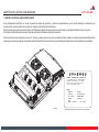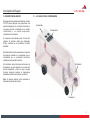
1
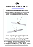
Aire Acondicionado
Miniómnibus - Microomnibus
Air Conditioner
Minibus - Midbus
Manual del Proprietário / Certificado de Garantía
Owner’s Manual / Warranty Certificate
Recomendamos leer atentamente este manual antes de empezar la
operación del aire acondicionado, para obtener el mejor desempeño .
Tenga el manual siempre en manos para futuras referencias.
We recommend a careful reading of this manual prior starting the
operation of your air conditioner, to obtain its best performance.
Keep it for future references..
CC 145T
Término de Garantía Spheros
1 - TÉRMINOS DE GARANTÍA SPHEROS
7 – L A GARANTÍA PERDERÁ SU VALIDAD:
LA SPHEROS CLIMATIZAÇÃO DO BRASIL S/A garantiza sus productos por
un período de un año, contados a partir de la fecha de instalación del equipo,
que consta en el cuerpo del certificado de garantía.
Si el equipo es instalado por un tercero la Spheros garantiza solamente el
producto y no la instalación del mismo.
Ninguna reivindicación será acepta si el vehículo continua siendo usado
después de constatado el defecto, mismo que haya falta de piezas, atraso en
el transporte o cualquier otro incidente.
a) Si la instalación o utilización del producto estuviera en desacuerdo con las
recomendaciones técnicas de la Spheros.
b) Si el producto sufrir cualquier daño provocado por accidente, agentes de la
naturaleza, malos tratos, o aún alteraciones y reparos realizados por
personas no autorizadas por el fabricante.
c) Si el certificado de garantía o el número de serie del producto estuviera
adulterado, rasurado o damnificado.
d) Si defectos y desempeño insatisfactorios son provocados por la utilización
de piezas no originales y en desacuerdo con las especificaciones técnicas de
la SPHEROS.
1- La garantía tendrá validad por el plazo arriba especificado, empezando a
partir de la fecha de instalación del equipo, mismo que la propiedad del
producto cambie de dueño.
2- Durante el período estipulado, la garantía cubre totalmente la mano de obra
y piezas para reparos de defectos debidamente constatados como siendo de:
fabricación del equipo; falla prematura de material y defectos de componentes
utilizados en la fabricación del mismo.
3- Solamente un técnico de la red de servicio autorizado Spheros está
habilitado a reparar defectos cubiertos por la garantía.
4- El reparo o sustitución de piezas defectuosas, realizado por el servicio
autorizado, no tendrá débito de piezas y/o mano de obra al cliente.
5- La aprobación de la garantía está condicionada al analice técnica del
defecto presentado en el componente y a condiciones operacionales a que el
equipo fue sometido.
6- La garantía de componentes utilizados en montaje de equipos Spheros,
que poseen red propia de asistencia técnica, será obtenida junto a su red,
mediante la presentación del certificado de garantía Spheros.
Como ejemplo el caso del alternador, que debe ser encaminado para la red
Bosch.
8 – LA GARANTÍA NÃO CUBRE:
a) Traslado del producto para reparos. Si el consumidor desea ser atendido en
sus instalaciones, quedará a criterio del Servicio Autorizado la cobranza o
cortesía de la tasa de visita.
b) La asistencia al consumidor, gratuita o remunerada, en ciudades que no
poseen Servicio Autorizado. Así los costos con traslados son de total
responsabilidad del propietario.
c) Falta de mantenimiento preventivo, conforme descrito en este manual, en el
ítem mantenimiento preventivo.
d) Revisiones, ajustes y limpieza, pues estas informaciones constan en el
manual del propietario.
e) Piezas que sufrieron desgastes considerados naturales.
Son considerados componentes de desgastes naturales: correas, filtros en
general, aceites lubrificante, relees y fusibles.
f) Pérdidas o lucros cesantes ocasionados por la parada del vehículo debido al
mal funcionamiento del equipo de aire acondicionado.
LA GARANTÍA SOLAMENTE SERÁ VALIDADA MEDIANTE LA
PRESENTACIÓN DEL CERTIFICADO DE GARANTÍA ORIGINAL.
3
Spheros Warranty Terms
1 - SPHEROS WARRANTY TERMS
7 – THE WARRANTY LOSES ITS VALIDITY:
SPHEROS CLIMATIZAÇÃO DO BRASIL S/A guarantees its products for the
period of one year, counted from the equipment installation date, which is
stated on the cover of the warranty certificate.
In case a third party installs the equipment, Spheros guarantees only the
product and not its installation.
No claim will be accepted if the vehicle continues to be used after the evidence
of defect, even if there is lack of parts, delays in transportation or any other
incident.
a) If the installation or use of the product is not in accordance with the Spheros
technical recommendations.
b) If the product suffers any damage caused by accident, nature agents,
misuse, or yet alterations and repairs performed by any other than the
manufacturer’s authorized technicians.
c) If the warranty certificate and/or the serial number of the product is
adulterated, overwritten or damaged.
d) If defects or unsatisfactory performance are caused by the use of not
original spare parts and in disagree with the technical specifications from
SPHEROS.
1- The warranty will be valid for the period above specified, counted from the
equipment installation date made by the first buyer/consumer, even though the
property has been transferred.
2- During the stipulated period, the warranty covers totally the workmanship
and spare parts when repairing defects duly identified as being: equipment
manufacturing; primary failure of material and defects of components used on
its manufacturing.
8 – THE WARRANTY DOES NOT COVER:
5- The warranty approval is conditioned to the technical analysis of the defect
presented on the components and operational conditions to which the
equipment was submitted.
a) Transportation expenses to the repair facility. In case the consumer decides
to be attended in the same place the product operates, the collection or not of
the visit tax will be the criterion of the Authorized Service.
b) The attendance to the consumer, free or paid, in cities that do not have
Authorized Services. Being thus the expenses with displacement are of total
responsibility of the owner.
c) Failure of proper preventative maintenance, according to the described in
this manual, on the preventative maintenance item.
d) Revisions, external adjustments and cleaning, therefore these information
are listed on the owner’s guide.
e) Parts that wear out naturally.
Are considered components of natural wear out: belts, filters in general,
lubricant oil, relays and fuses.
f) Losses or losses of profits caused by the stop of the vehicle due to the not
functioning of the air conditioning equipment.
6- The warranty of the components used on the assembly of the Spheros
equipment, which have their own net of technical assistance, will be obtained
from its own net, by presenting the Spheros warranty certificate. Having as
example the alternator case, it should be forwarded to the Bosch net.
THE WARRANTY WILL ONLY BE VALID BY PRESENTING THE
ORIGINAL WARRANTY CERTIFICATE.
3- Only a technician from the spheros authorized net of services is qualified to
repair the defects covered by the warranty.
4- The repair or replacement of defective parts, performed by an authorized
service station, will not incur in any debit regarding parts and workmanship
used.
4
Índice / Index
1 - INTRODUCCIÓN ...................................................................................................... 6
1 - IDENTIFICACIÓN DEL AIRE ACONDICIONADO..................................................... 7
2 - OPERACIÓN ............................................................................................................ 8
2.1 - INFORMACIONES GENERALES DE OPERACIÓN ......................................... 8
2.1.1 - ACCIONAMIENTO DEL CONDENSADOR .................................................. 8
2.1.2 - ACCIONAMIENTO DEL EVAPORADOR ..................................................... 8
2.1.3 - ACCIONAMIENTO DEL COMPRESOR ....................................................... 8
2.1.4 - SISTEMA DE PROTECCIÓN ....................................................................... 8
2.2 - OPERACIÓN DEL AIRE ACONDICIONADO - CONTROLADOR GLW 161 ..... 9
2.2.1 - MODO REFRIGERACIÓN ........................................................................... 9
2.2.2 - MODO VENTILACIÓN ................................................................................. 9
2.2.3 - PROGRAMANDO EL SET-POINT............................................................... 10
2.2.4 - FALLAS ....................................................................................................... 10
3 - DESCRIPCIÓN DEL EQUIPO ................................................................................. 11
3.1 - LOCALIZACIÓN DE COMPONENTES ........................................................... 11
3.2 - ESPECIFICACIONES TÉCNICAS.................................................................... 12
3.2.1 - COMPONENTES DEL EQUIPO ................................................................. 13
4 - MANUTENCIÓN PREVENTIVA ............................................................................. 14
4.1 - TABLA DE FRECUÊNCIA PARA MANUTENCIÓN PREVENTIVA ................. 14
4.2 - VERIFICACIÓN DE LA CARGA DE GAS REFRIGERANTE .......................... 16
EN EL SISTEMA
LEYENDA ELÉCTRICA .............................................................................................. 17
5 - ESQUEMAS ELÉTRICOS ..................................................................................... 18
1 - INTRODUCTION....................................................................................................... 6
1 - AIR CONDITIONER IDENTIFICATION .................................................................. 20
2 - OPERATION .......................................................................................................... 21
2.1 - OPERATION GENERAL INFORMATION ........................................................ 21
2.1.1 - TURNING THE CONDENSER ON ............................................................ 21
2.1.2 - TURNING THE EVAPORATOR ON .......................................................... 21
2.1.3 - TURNING THE COMPRESSOR ON ......................................................... 21
2.1.4 - PROTECTION SYSTEM ............................................................................ 21
2.2 - AIR CONDITIONER OPERATION - GLW 161 CONTROLLER ....................... 22
2.2.1 - COOLING MODE ....................................................................................... 22
2.2.2 - VENTILATION MODE ................................................................................ 22
2.2.3 - PROGRAMMING THE SET-POINT ............................................................ 23
2.2.4 - FAILURES................................................................................................... 23
3 - EQUIPMENT DESCRIPTION ................................................................................ 24
3.1 - COMPONENTS LOCATION ........................................................................... 24
3.2 - TECHNICAL SPECIFICATION ........................................................................ 25
3.2.1 - EQUIPMENT COMPONENTS ................................................................... 26
4 - PREVENTATIVE MAINTENANCE ......................................................................... 27
4.1 - FREQUENCY SCHEDULE FOR PREVENTATIVE MAINTENANCE .............. 27
4.2 - VERIFICATION OF REFRIGERANT GAS LOAD IN THE SYSTEM ............... 29
5 - ELECTRICAL SCHEME ......................................................................................... 30
5
Introducciónes / Introduction
INTRODUCCIÓN
INTRODUCTION
La Spheros desenvuelve sus productos preocupada en ofrecer a los
pasajeros un ambiente confortable, buscando siempre la mejor condición de
climatización.
Spheros develops its products worried in offering to the passengers a
comfortable environment, always looking for the best air conditioning
concepts.
Los equipos poseen simplicidad de operación y una gran precisión de control.
Los sistemas con dimensiones optimizadas, garantiza una alta capacidad de
resfriamiento con bajo nivel de ruido.
The equipments are simple to operate and have great precision of control. The
systems, with compact dimensions, guarantee a high cooling capacity with low
noise level.
Este manual fue desenvuelto con la finalidad de presentar aspectos
importantes de funcionamiento, operación y manutención, para que se
obtenga el mejor desempeño del equipo de aire acondicionado.
This manual was developed with the purpose of presenting important
functioning aspects, operation and maintenance, to obtain the best
performance out of the air conditioning system.
Para asegurar que el equipo tenga una larga vida útil y libre de problemas es
imprescindible que las instrucciones de operación y manutención descritas en
este manual sean seguidas y ejecutadas periódicamente.
To ensure a long useful and problem free life to the equipment it is essential
that the operation and maintenance instructions described in this manual are
followed and performed periodically.
Los controladores instalados por la Spheros y utilizados por el conductor
están debidamente ilustrados y explicados en este manual.
All controls installed by Spheros, which are used by the driver, are duly
illustrated and explained in this manual.
Es importante que el conductor lea atentamente las instrucciones de
operación antes de iniciar la operación del equipo de aire acondicionado.
It is important that the driver reads the operation instructions carefully before
starting to operate the air conditioning equipment.
La Spheros mantiene una red de servicio autorizado con herramientas,
aparatos y un equipo de personas entrenadas para ejecutar cualquier tipo de
manutención dentro de los padrones de calidad.
Spheros keeps a net of authorized services with tools, equipments and a team
of professionals trained to perform any type of maintenance within the quality
standard.
Agradecemos la preferencia por los productos Spheros. En caso de dudas
entre en contacto con la red de servicio autorizado Spheros más próximo o
comuníquese con el departamento de Asistencia técnica en la fabrica.
Thank you for choosing Spheros products. In case of any doubt please contact
the nearest Spheros’s authorized net of services or contact the technical
assistance department..
6
Identificación del Aire Acondicionado
1 - IDENTIFICACIÓN DEL AIRE ACONDICIONADO
Es de fundamental importancia, en casos de pedidos de piezas de reposición, y demás correspondencias, que el cliente identifique el modelo del aire
acondicionado, mencionando el número de serie, modelo y fecha de fabricación del mismo.
Estas informaciones podrán ser encontradas en el Certificado de garantía del equipo del aire acondicionado y en la tarjeta de identificación (ver figura 1).
En la tarjeta consta también el tipo de gas refrigerante utilizado y cantidad necesaria para el modelo.
Informaciones referentes a aplicaciones como: N° de serie y modelo de carrocería; serie y modelo de chasis, también son importantes para la identificación de
piezas que componen el equipo de aire acondicionado. Para identificación de la carrocería y del chasis los manuales de los mismos deben ser consultados.
SPHEROS CLIMATIZAÇÃO DO BRASIL SA
AV. RIO BRANCO NRO 4688 - B SÃO CRISTÓVÃO
95060-650 - CAXIAS DO SUL - RS - BRASIL
Fone (54) 2101 5700 Fax 9540 2101 5747
E-mail: [email protected]
Equipo
Modelo.......:
Codigo.......:
No. Serie....:
Fecha........:
GAS
Tipo.: R 134 a
CC145T
100-00000-000
99999999999
00/00/00
Cd.:3,7Kg
figura 01
* la cantidad de refrigerante puede variar de una aplicación
7
Operación
2 - OPERACIÓN
2.1.2 - ACCIONAMIENTO DEL EVAPORADOR
2.1 - INFORMACIONES GENERALES DE OPERACIÓN
El control de velocidad de los ventiladores del evaporador es hecho
automáticamente de acuerdo con la temperatura programada y la
temperatura interna del coche.
Los controladores de los equipos de aire acondicionado Spheros son
normalmente instalados en el panel de la cabina del conductor. Son
compuestos por un display y un teclado destinado a la operación del equipo.
El display informa al operador el valor de la temperatura interna del vehículo.
También es utilizado para visualización del status de la operación y
programación de la temperatura del Set-point*.
La temperatura interna es detectada por el sensor de temperatura ubicado en
el retorno de aire del equipo. (ver iten 3.1).
Importante: El equipo de aire acondicionado solamente funcionará con el
motor del vehículo prendido. Recomendase siempre apagar el aire
acondicionado antes de apagar el motor del vehículo.
Obs.: Antes de encender el aire acondicionado verifique las condiciones de
las correas del compresor localizado junto al motor del vehículo (ver iten 3.1).
Cuando la temperatura interna llega próxima del set-point, la velocidad de los
ventiladores es reducida y cuando la temperatura interna se aleja del setpoint, la velocidad de los ventiladores aumenta automáticamente.
Para equipos instalados en coches utilizados en líneas urbanas, donde existe
una necesidad mayor de refrigeración, la ventilación funciona solamente a
velocidad alta.
2.1.3 - ACCIONAMIENTO DEL COMPRESOR
El compresor trabaja solamente en el “Modo refrigeración”, y entrará en
operación 10 segundos después de que el evaporador sea accionado.
Por motivos de seguridad los controladores poseen una histerese de tiempo
de 30 seg. para rearmar el compresor toda vez que él mismo se apague.
2.1.1 - ACCIONAMIENTO DEL CONDENSADOR
2.1.4 - SISTEMA DE PROTECCIÓN
Los ventiladores del condensador, así como el compresor, solamente serán
accionados cuando el equipo del aire acondicionado funcione en el “Modo
Refrigeración”.
Los equipos poseen un sistema eléctrico que monitora sus presiones de
trabajo. Este monitoreo es hecho por presostatos**.
Cuando ocurriera una falla en el equipo y las presiones de trabajo del sistema
sufrieren una alteración, el controlador recibirá una señal de los presostatos y
el display mostrará un código de falla (ver fallas en el iten 2 –Operación). Para
seguridad del compresor el mismo será apagado inmediatamente.
* Set-point – es el valor de temperatura deseado en el interior del vehículo, ajustada por el operador
(conductor).
** Presostato – dispositivo de seguridad que protege los componentes del sistema del aire acondicionado
contra altas y bajas presiones.
Obs.: Las presiones son monitoreadas constantemente mismo si el aire
acondicionado estuviera apagado.
8
Operación
2.2 - OPERACIÓN DEL AIRE ACONDICIONADO - CONTROLADOR
GLW161
Al accionar la llave de ignición, el display, primeramente mostrará la versión
del software del controlador, después mostrará la temperatura interna del
vehículo. Antes de poner el motor en marcha el display mostrará la sigla AL
(ver iten 2.2.4).
6
7
8
9
1
3
4
5
1 - Display numérico
2 - Tecla control de ventilación (VENT.)
3 - Tecla control de refrigeración (REFRIG.)
4 - Tecla (AUMENTA)
5 - Tecla (DISMINYE)
6 - Indicativo “modo refrigeración”
7 - Indicativo “modo automático”
8 - Indicativo “modo ventilación velocidad baja”
9 - Indicativo “modo ventilación velocidad alta”
2
2.2.1 - MODO REFRIGERACIÓN
1- Para encender el equipo presione la tecla (REFRIG).
El “modo refrigeración” encenderá automáticamente en función de la
temperatura interna del vehículo y de la temperatura ajustada.
La operación del modo refrigeración será señalizada conforme información
abajo.
a) Indicativo (6) apagado informa que el “modo refrigeración” está
apagado
b) Indicativo (6) parpadeando informa que el equipo está trabajando en el
“modo ventilación”
c) Indicativo (6) encendido informa que el “modo refrigeración” está
encendido.
2 - Para desactivar el “modo refrigeración”, presione nuevamente la tecla
(REFRIG).
Siempre que el sistema inicie en el “modo refrigeración” los ventiladores del
evaporador empezarán en el “modo automático”. Pero, la velocidad puede ser
alterada manualmente (ver iten 2.3.2).
El accionamiento de los ventiladores del evaporador en el modo automático
es hecho de acuerdo con la programación del set-point.
2.2.2 - MODO VENTILACIÓN
El “modo ventilación” proporciona dos velocidades de operación:
1- Con el “modo refrigeración” desactivado presione la tecla (VENT) y el aire
acondicionado funcionará solamente en ventilación. El indicativo (8) quedará
encendido para informar que la ventilación está operando en velocidad baja.
2- Para que los ventiladores operen en velocidad alta, presione nuevamente la
tecla (VENT). Esta función será informada por el indicativo (9) encendido.
3- Presionando una vez más la tecla (VENT) desactivará el “modo ventilación”
9
Operación
Con el “modo refrigeración” activado la velocidad de la ventilación es
normalmente automática, y será informada por el indicativo (7) encendido.
Aunque la velocidad puede ser alterada manualmente, siguiendo los mismos
pasos informados anteriormente.
4 - Para volver al control automático, presione la tecla (VENT) hasta que el
indicativo (7) encienda, informando que la ventilación está en el modo
automático.
2.2.4 - FALLAS
Este controlador posee un sistema de monitoreo de fallas. Cuando ocurra
alguna falla en el sistema del aire acondicionado, el display mostrará una
alarma conforme información abajo.
FALHA
DESCRIÇÃO
2.2.3 - PROGRAMANDO EL SET-POINT
Falla de presostato
1- Para ajustar el set-point presione una de las teclas (AUMENTA) o
(DISMINUYE). La temperatura del set-poit aparecerá parpadeando en el
display.
Sensor de temperatura abierto
2- Para programar el set-point basta presionar la tecla (AUMENTA) para
aumentar la temperatura o la tecla (DISMINUYE) para disminuir la
temperatura, hasta encontrar la temperatura deseada.
3- Después de la temperatura deseada definida, el display continuará
parpadeando por 5 segundos. Cuando pare de parpadear el mismo mostrará
la temperatura interna del vehículo y la temperatura del set-point estará
reprogramada
Sensor de temperatura en corto
Falla del alternador
1- Si ocurriera alguna falla de presostato, el display mostrará la alarma (HA) y
el sistema apagará el compresor. Después de corregida la falla, el sistema
aguardará 3 minutos para accionar nuevamente el compresor.
2- Como el sistema opera en función de la temperatura interna el controlador
posee dos códigos de falla para monitorear el sensor de temperatura:
a) Si el sensor de temperatura estuviera abierto el display mostrará (OP)
b) Si el sensor de temperatura estuviera en corto circuito el display
mostrará (SC)
3- Este controlador posee un parámetro para monitorear el alternador. Caso el
alternador no estuviera cargando el display mostrará el código (AL).
Importante: Al identificar cualquier falla en el sistema del aire acondicionado,
el vehículo deberá ser encaminado a un puesto de servicio autorizado
Spheros.
10
Descripción del Equipo
3 - DESCRIPCIÓN DEL EQUIPO
El equipo del aire acondicionado Spheros, modelo
CC145T posee designer que proporciona una
perfecta integración con el vehiculo. Consiste en
un equipo de techo, constituido por un módulo
conden sador y un modulo evaporador,
conectados a un compresor.
3.1 - LOCALIZACIÓN DE COMPONENTES
Evaporador
Condensador
El compresor está ubicado junto al motor del
vehículo. El producto utiliza gas refrigerante
R134a, conforme ley de protección al medio
ambiente.
El sistema eléctrico está compuesto por una placa
de potencia, ubicada en el evaporador que es
comandada por un controlador electrónico
ubicado junto al panel del conductor.
Controlador
El controlador recibe información del sensor de
temperatura, que está ubicado en el retorno del
aire del evaporador, y hace con que el equipo
funcione buscando alcanzar la temperatura
deseada en el interior del vehículo. (ver item 2)
Obs.: El sistema eléctrico está conectado al
alternador y baterías del vehículo.
Compresor
11
Especificaciones Técnicas
3.2 - ESPECIFICACIONES TÉCNICAS
FICHA TÉCNICA
AIRE ACONDICIONADO
GAS REFRIGERANTE
Modelo
Capacidad de refrigeración
Tipo
Cantidad
CC-145T
45.000 BTU/hR
R 134a
3,7 kg*
EVAPORADOR
Modelo de ventiladores
Cantidad de ventiladores
Volumen de aire
Corriente nominal
centrífugo
2
2040 m3/h
38 A
CONDENSADOR
Modelo de ventiladores
Cantidad de ventiladores
Volumen de aire
Corriente nominal
axial
2
5500 m3/h
32 A
COMPRESOR
EMBRAGUE
Modelo (Tipo revolución)
Deslocación
Máxima rotación por minuto
Aceite lubricante
Cantidad de aceite
SP 22
212 cm3
4500 RPM
027-00001-000
180 ml
Tipo
Voltaje
eletromagnética
12 v
12
Componentes del Equipo
3.2.1 - COMPONENTES DEL EQUIPO
1
2
4
5
3
8
7
6
ITEM
DESCRIPCIÓN
CÓDIGO
ITEM
1
Ventilador condensador 12” 24v
021-00021-001
5
Serpentin evaporador
DESCRIPCIÓN
006-00090-000
CÓDIGO
2
Serpentín condensador
006-00089-000
6
Válvula de expansión
012-00004-000
3
Filtro deshidratador / mirrilla / tanque
012-00074-000
7
Sensor de temperatura
007-00042-000
4
Ventilador evaporador 12V
021-00020-001
8
Placa de relees GL-T043 12V
007-00001-000
13
Manutención Preventiva
4 - MANUTENCIÓN PREVENTIVA
4.1 - TABLA DE FRECUENCIA PARA MANUTENCIÓN PREVENTIVA
Las acciones de manutención preventiva aquí descriptas, fueran consideradas para condiciones operacionales normales. Caso las condiciones sean de
grande solicitación y contaminación ambiental, las acciones preventivas deberán ser mas frecuentes.
REFRIGERACIÓN
Instalar los manómetros y registrar las presiones, temperatura y condiciones de la línea de succión;
Verificar la carga del refrigerante después de 15min de funcionamiento;
Inspeccionar visualmente si hay marcas de desgastes y deterioración en tuberías y mangueras;
Inspeccionar visualmente se hay señales de fuga de aceite e refrigerante;
Verificar las presiones de abertura y cerramiento de los presostatos;
Verificar la eficiencia del compresor.
Mensual Trimestral Anual
COMPRESOR / EMBRAGUE
Inspeccionar visualmente si hay desgaste en la embrague;
Verificar visualmente las condiciones, tensión y alineamiento de las correas del compresor;
Limpiar el compresor y embrague;
Verificar la resistencia y voltaje en la bobina (magneto).
Mensual Trimestral Anual
ESTRUCTURA
Inspeccionar visualmente si hay piezas sueltas, dañadas o quebradas;
Limpiar o sustituir el filtro del retorno del aire;
Limpiar los drenes del condensador y evaporador;
Limpiar el serpentín del condensador (utilizar jabón neutro);
Limpiar el serpentín del evaporador (utilizar jabón neutro);
Reapretar todos los tornillos del soporte del compresor y de la unidad observando los torques aplicados.
Verificar la tapa del equipo.
Mensual Trimestral Anual
X
X
X
X
X
X
X
X
X
X
X
X
X
X
X
X
X
14
Manutención Preventiva
ELÉCTRICA
Mensual Trimestral Anual
Verificar la secuencia del termostato (refrigeración / ventilación / calefacción);
Verificar el alternador;
Verificar el aprieto del cable de potencia en el alternador, fusible general, placa de relees y arranque
Inspeccionar visualmente las correas del alternador observando la tensión, alineamiento y desgaste excesivo;
Limpiar el alternador, verificar marcas de corrosión y las conexiones eléctricas;
X
Verificar el funcionamiento de las velocidades alta y baja de los ven. evaporador y el flujo de aire de los vent. evaporador e condensador
X
X
X
X
X
Limpiar la area donde está el controlador y el sensor de temperatura. Utilizar aire comprimido;
Inspeccionar todos los cables y conexiones eléctricas, verificando daños y corrosión.
X
X
Nota: Recomendamos utilizar esa tabla para desarrollar un plan de manutención periódica en sus vehículos..
IMPORTANTE: La limpieza del filtrador del retorno del aire localizado en el pasillo del vehículo y el
serpentín del condensador localizada en la parte externa del vehículo, deberá ser realizada por el
propietario con una periodicidad semanal, la no realización de estos servicios podrá ser encuadrada
como negligencia, cancelando la garantía.
La limpieza de los conductos del aire deberá ser hecha con una periodicidad trimestral y este tiempo
puede ser reducido, dependiendo de la utilización del sistema del aire acondicionado, de la cantidad de
personas transportadas y de la agravación sufrida por el medio adónde transita. Esta limpieza es de
responsabilidad exclusiva del propietario del vehículo, a él le cabrá todo el ónus de la mala calidad del aire
ofrecido a sus pasajeros.
15
Manutención Preventiva
4.2 - VERIFICACIÓN DE LA CARGA DE GAS REFRIGERANTE EN EL
SISTEMA
Después que el sistema del aire acondicionado esté funcionando por
aproximadamente 5 minutos, con el embrague magnético acoplado y el motor
del vehículo funcionando a una revolución mínima de 1500RPM, El
refrigerante deberá fluir a través de la mirilla del líquido sin la formación de
burbujas.
Nota: Los refrigerantes no deben ser lanzados a la atmósfera (8, CFC directiva prohibitiva de Halon, 06/05/1991).
4.3 - CUIDADOS DURANTE EL INVIERNO
Para prevención contra fugas en el sello del compresor, prenda el aire
acondicionado por 15 minutos. Esa operación debe ser ejecotada dos veces
al mes a una temperatura superior a 8°C. El tanque recibidor y los otros
componentes del sistema del aire acondicionado deberán ser
inspeccionados.
Durante las actividades de manutención, una atención especial debe ser dada
para señales de corrosión o algún daño mecánico. Todos los componentes
que no estuvieran en perfecto estado deberán ser sustituidos por motivo de
seguridad.
Atención: En caso que ocurra un problema en el circuito de refrigeración, el
mismo deberá ser reparado por un taller autorizado, o por un profesional
capacitado.
16
Leyendas Eléctricas
BATERIA
E-BATTERY
S-BATERÍA
!M
M
+15 ( + PÓS IGNIÇÃO)
E- + POS IGNITION
S- + POS IGNICIÓN
!
ALTERNADOR
E-ALTERNATOR
S-ALTERNADOR
M
PRESSOSTATO ALTA
E-HIGH PRESSURE SW
S-PRESSOSTATO ALTA
GND
E-GROUND
S-TIERRA
PRESSOSTATO BAIXA
E-LOW PRESSURE SW
S-PRESSOSTATO BAJA
SENSOR EXTERNO
E-EXTERNAL SENSOR
S-SENSOR EXTERNO
CHAVE IGNIÇÃO
E-IGNITION KEY
S-LLAVE DE IGNICIÓN
SENSOR DE RETORNO
E-RETURN SENSOR
S-SENSOR DE VUELTA
RELÉ
E-RELAY
S-RELAI
SENSOR DE DUTO
E-DUCT SENSOR
S-SENSOR DEL DUCTO
1
2
VÁLVULA CALEFAÇÃO
E-HEATING VALVE
S-VÁLVULA DEL CALEFAC.
PLACA DE RELÉS
E-RELAY BOARD
S-TABLERO DEL RALAIS
CONVECTOR PISO
E-CONVECTOR
S-CONVECTOR
TERMOSTATO ICE
E-ICE THERMOSTAT
S-TERMÓSTATO ICE
COM 1
E-COMUNICATION 1
S-COMUNICACIÓN 1
SOLENÓIDE L. LIQUIDO
E-SOLENOID LINE LIQUID
S-SOLENOIDE L.LIQUIDO
COM 2
E-COMUNICATION 2
S-COMUNICACIÓN 2
B
BOMBA CALEFAÇÃO
E-HEATING PUMP
S-BOMBA CALEFACCIÓN
COM 3
E-COMUNICATION 3
S-COMUNICACIÓN 3
EVAPORADOR MÉDIA
E-AVERAGE EVAPORATOR
S-EVAPORADOR MEDIO
EMBREAGEM
E-CLUTCH
S-EMBRAGUE
FUSÍVEL
E-FUSE
S-FUSIBLE
EVAPORADOR BAIXA
E-LOW EVAPORATOR
S-EVAPORADOR BAJA
CORRENTE MÁXIMA
E-MAXIMUM CURRENT
S-CORRIENTE MAXIMA
RENOVAÇÃO DE AR
E-FRESH AIR
S-RENOVACIÓN DEL AIRE
CONDENSADOR
E-CONDENSER
S-CONDENSADOR
EVAPORADOR ALTA
E-HIGH EVAPORATOR
S-EVAPORADOR ALTA
LÂMPADA EXCITAÇÃO
E-EXCITEMENT LAMP
S-EXCITACIÓN LAMP
CORTINA DE AR
E-AIR CURTAIN
S-CORTINA DE AIRE
POSITIVO DIRETO
E- POSITIVE (DIRECT)
S- POSITIVO (DIRECTO)
EVAPORADOR
E-EVAPORATOR
S-EVAPORADOR
OBS: Por tratar-se de equipamento elétrico
com comutação de alta corrente, é
indispensável que este seja instalado em
local ventilado, não enclausurado, longe de
tubulações de combustíveis ou inflamáveis,
sob risco de incêndio/explosão.
O equipamento não tem proteção contra
água. Jatos ou respingos podem danificálo.
3
PS: Because this is an electrical control
equipment with high commuting current, it is
very important to be installed at a vented,
open space, far from fuel/flammable
material pipelines under the risk of
fire/explosion.
This equipment is not protected against
water. Jets or splashes of water may
damage it. The power screw must be
tighten up so that the risk of fire because of a
bad electrical contact may be avoid.
PS: Como esto es un equipo eléctrico del
control con la corriente que conmuta del
colmo, es muy importante ser instalado en
un espacio expresado, abierto, lejos del
combustible/de las tuberías materiales
inflamables, riesgo del fuego/de la
explosión.
Este equipo no se protege contra el agua.
Los salpican del agua pueden dañarla. El
tornillo de la energía debe ser aprieta para
arriba de modo que el riesgo del fuego
debido a un mal contacto eléctrico pueda
ser evite.
17
Esquemas Elétricos
5 - ESQUEMAS ELÉCTRICOS CC 145T CON CONTROLADOR GL-W161
RL3
RL6
1 - CONECTA CONDENSADOR
2 - MOTOR COND. 1
F7
3 - MOTOR EVAP. V. BAJA 1
4 - CONECTA EVAP. V. ALTA
F3
5 - CONECTA EVAP. V. BAJA
6 - SALIDA P/ CORTINA DEL AIRE
F5
RL2
F1
RELEES
7 - N.C
RL5
8 - MOTOR EVAP. V. ALTA
9 - EXCITACIÓN ALTERNADOR
CN2
F4
F2
RL1
CN1
RL4
F8
F9
1 - N.C
2 - MOTOR COND. 2
MAXIMAS CORRIENTES ADMISIONES CN1:
3 - EMBRAGUE
4 - TIERRA
RL7
RL8
J
DEL AIRE - 0,5A@14VDC
5 - +12V
6 - N.C
7 - MOTOR EVAP. V. ALTA
MAXIMAS CORRIENTES ADMISIONES CN2:
8 - MOTOR EVAP. V. BAJA 2
9 - MOTOR COND. 3
EMBRAGUE - 10A
J
67,6
PS: Como esto es un equipo eléctrico del control
con la corriente que c on muta del colmo, es muy
importante ser instalado en un espacio expresado,
abierto, lejos del combustible/de las tuberías
materiales inflamables, riesgo del fuego/de la
explosión. Este equipo no se protege contra el agua.
Los salpican del agua pueden dañarla. El tornillo de la
energía debe ser aprieta para arriba de modo que
el riesgo del fuego debido a un mal contacto
eléctrico pueda ser evite.
ESTE DESENHO É DE PROPRIEDADE DE SPHEROS CLIMATIZAÇÃO DO BRASIL, É CONFIDENCIAL, NÃO DEVE SER DIVULGADO OU REPRODUZIDO SEMSEM EXPRESSA E ESCRITA
PERMISSÃO DA COMPANHIA.
THIS DRAWING IS PROPRIETY OF SPHEROS CLIMATIZAÇÃO DO BRASIL, IS CONFIDENCIAL, IT MUST NOT BE RELEASED OR COPIED WITHOUT WRITTEN AND EXPRESS PERMITION
BY THE WCB.
Part Name
GL-T043 12V
Date
Drawing nº:
12/05/2009
007-00001-000
18
Esquemas Eléctricos
(VM/1,5)
(MA/1,5)
(VE/1,5)
(MA/1,5)
GL-W161
(LA/1,5)
(LI/1,5)
(BR/1,5)
(PR/1,5)
12V
PS:
GL-T043
RL2
RL1
RL5
RL3
RL6
RL4
RL7
*
Dependendo da combinação
CHASSI x ALTERNADOR, não
ligar em paralelo.
RL8
Depending on the combination
CHASSIS x ALTERNATOR, do
not connect in parallel.
RL6
RL5
RL7
RL3
RL8
RL4
F2
30A
F7
30A
F5
20A
F8
10A
F3
20A
F9
20A
F4
20A
(AZ/1,5)
RL1
F1
20A
(VM/25,0)
RL2
(VM/25,0)
Dependiendo de lacombinación
ALTERNADOR x CHASIS, no
atar en paralelo.
(PR/25,0)
ESTE DESENHO É DE PROPRIEDADE DE SPHEROS CLIMATIZAÇÃO DO BRASIL, É CONFIDENCIAL, NÃO DEVE SER DIVULGADO OU REPRODUZIDO SEMSEM EXPRESSA E ESCRITA
PERMISSÃO DA COMPANHIA.
THIS DRAWING IS PROPRIETY OF SPHEROS CLIMATIZAÇÃO DO BRASIL, IS CONFIDENCIAL, IT MUST NOT BE RELEASED OR COPIED WITHOUT WRITTEN AND EXPRESS PERMITION
BY THE WCB.
Part Name
GL-T043 12V
Date
Drawing nº:
12/05/2009
007-00001-000
19
Air Conditioner Identification
1 - AIR CONDITIONER IDENTIFICATION
It is extremely important, when ordering spare parts and sending other correspondences, that the customer identifies the air conditioner model, mentioning
serial number, model and manufacturing date.
This information may be found on the air conditioner's Warranty Certificate and on the identification tag. (See picture 1)
On this tag it is also informed the refrigerant gas to use and necessary quantity for the model. *
Information regarding the application such as: body serial number and model; chassis serial number and model, are also important to identify the spare parts
that comprise the cooling equipment. To identify the body and the chassis, their manuals should be consulted.
SPHEROS CLIMATIZAÇÃO DO BRASIL SA
AV. RIO BRANCO NRO 4688 - B SÃO CRISTÓVÃO
95060-650 - CAXIAS DO SUL - RS - BRASIL
Fone (54) 2101 5700 Fax 9540 2101 5747
E-mail: [email protected]
Equipment
Model........:
Code.........:
Serial nº....:
Date.........:
GAS
Type.: R 134 a
CC145T
100-00000-000
99999999999
00/00/00
Qt.:3,7Kg
figura 01
* the amount of refrigerant may vary by application
20
Operation
2 - OPERATION
2.1.2 - TURNING THE EVAPORATOR ON
This air conditioning model offers different options of control. Identify the
controller visually and, after that, choose the compatible working instructions.
The velocity control from the evaporator blower is automatically adjusted
according to the temperature programmed and the temperature inside the
vehicle.
2.1 - OPERATION GENERAL INFORMATION
When the internal temperature reaches close to set-point, the velocity of the
blower is reduced and when the internal temperature gets distant from setpoint, the velocity of the blower increases automatically.
Spheros air conditioner controllers are usually installed on the driver's
instruments dash. The controllers are composed of a display and a keyboard,
used to operate the equipment.
For equipment installed in city line vehicles, where the cooling need is greater,
the ventilation works only on high velocity.
The display shows the operator the number regarding the internal temperature
of the vehicle. It is also used to visualize the operation status and programming
the Set-Point* temperature.
2.1.3 - TURNING THE COMPRESSOR ON
The internal temperature is detected by a temperature sensor located at the
(see item 3.1)
The compressor operates only on "Cooling Mode", and will start operation 10
seconds after the condenser is turned on.
Important: the air conditioner will only work when the vehicle's engine is on.
It's always recommended to turn the air conditioner off before turning off the
vehicle.
For safety reasons the controllers present a time histeresis set in 30sec. to
restart the compressor every time it is turned off.
Note: Before turning on the air conditioner verify the conditions of the
compressor belts, located together to the vehicle's engine (see item 3.1) .
2.1.4 - PROTECTION SYSTEM
The devices are equipped with an electrical system that monitors its work
pressures. The pressure switch** performs this monitoring.
2.1.1 - TURNING THE CONDENSER ON
The condenser engines, as well as the compressor, will only be activated when
the air conditioner is working on the "Cooling Mode".
* Set-point – is the temperature figure which is desired inside the vehicle, adjusted by the operator (driver).
** Pressure Switch – safety device that protects the components from the air conditioning system against
high and low pressure.
When a failure in the equipment occurs and the work pressures suffer any
alteration, the controller receives a signal from the pressure switch and the
display will show a failure code (see failures on item 2 – Operation). For safety
reasons, the compressor will be automatically turned off.
Note: The working pressures are constantly monitored even when the air
conditioner is off.
21
Operation
2.2 - AIR CONTIDITONER OPERATION - GLW160 CONTROLLER- AIR
REFRESHMENT
When the ignition key is turned, the display will first show the controller's
software version, right after, the internal temperature of the vehicle. Before the
start the display will show the initials AL (see item 2.3.6)
6
7
8
9
1
1- To turn the equipment on, press the key (REFRIG).
The "cooling mode" will be automatically on according to the internal
temperature of the vehicle and the set temperature.
The cooling mode operation will be shown according to the described below:
a) Indicator (6) turned off informs that the "cooling mode" is off
b) Indicator (6) blinking informs that the equipment is running on
"ventilation mode"
c) Indicator (6) turned on informs that the "cooling mode" is on.
2- To shut the "cooling mode " press once again the key (REFRIG)
3
4
2.2.1 - COOLING MODE
2
Whenever the systems initiates on "cooling mode" the evaporator's blowers
will start on "automatic mode". However, the ventilation velocities may be
changed manually (see item 2.3.2).
The evaporator's blowers are activated, in the automatic mode, according to
the set-point programming.
5
2.2.2 - VENTILATION MODE
The "ventilation mode" provides two operation velocities:
1 – Numeric Display
2 – Ventilation control key (VENT)
3 – Cooling control key (REFRIG)
4 – Key (INCREASE)
5 – Key (DECREASE)
6 - Indicator "cooling mode"
7 - Indicator "automatic mode"
8 - Indicator "ventilation mode low velocity"
9 - Indicator "ventilation mode high velocity"
1- With the "cooling mode" shut, press the key (VENT) and the air conditioner
will work only on ventilation.
The indicator (8) will be on to inform that the ventilation is working at low
velocity.
2- To have the blowers working at high velocity, press (VENT) key again. This
function will be informed by having indicator (9) on.”
3- Pressing the key (VENT) one more time, the "ventilation mode" will be
turned off.
22
Operation
When the "cooling mode" on, the ventilation velocity is usually automatic, and
will be informed by the indicator (7) turned on. However, the ventilation
velocities can be altered manually, following the steps formerly described.
4- To return to the automatic control, press the key (VENT) until the indicator
(7) turns on, which informs that the ventilation is on automatic mode.
2.2.4 - PROGRAMMING THE SET-POINT
1- To adjust the set-point press on of the keys (INCREASE) or (DECREASE).
The set-point temperature will blink on the display.
2- To program it simply press the key (INCREASE) to increase the temperature
or the key (DECREASE) to decrease the temperature, until the desired
temperature is found.
3- After the desired temperature is selected, the display will keep blinking for 5
seconds. When it stops, it will show the internal temperature of the vehicle and
the set-point temperature will be reprogrammed.
2.2.5 - FAILURES
This controller is equipped with a failure system monitor. When any failure to
the air system occurs, the display will show a message according to the table
below:
FAILURES
DESCRIPTION
Pressure Switch failure
Temperature sensor open
Temperature sensor in shock
Alternator failure
1- If any failures occurs to the Pressure Switch, the display will show the
message (HA) and the system will shut the compressor off. The system will
wait for 3 minutes to turn the compressor on again, once the failure is
corrected.
2- As the system operates according to the internal temperature, the controller
possesses two failure codes to monitor the temperature sensor:
a) If the temperature sensor is open, the display will show (OP)
b) If the temperature sensor is in shock, the display will show (SC)
3- This controller possesses a parameter to monitor the alternator. In case of
failure or in case the alternator is not recharging, the display will show (AL).
Important: Whenever a failure to the air conditioner system is identified, the
vehicle must be sent to a Spheros authorized service station.
23
Operation
3 - EQUIPMENT DESCRIPTION
Spheros's air conditioner equipment, CC145T,
model, shows a perfect fitting design to the vehicle.
It consists of a roof equipment, composed by a
condenser module and a evaporator module
connected to a compressor.
3.1 - COMPONENTS LOCATION
Evaporator
Condenser
The compressor is located next to the vehicle's
engine. The product uses refrigerant gasR134a,
according to the environmental protection law.
The electrical system is composed of a power
panel, located on the evaporator, which is
controlled by the electronic controller positioned
together to the driver's panel.
The controller receives information from the
temperature sensor, situated on the air return, and
makes the equipment search and reach the
desired temperature inside the vehicle. (See item
2)
Controller
Note: The electrical system is inter-connected with
the vehicle's alternator and batteries.
Compressor
24
Technical Specifications
3.2 - TECHNICAL SPECIFICATIONS
TECHNICAL DATA SHEET
AIR CONDITIONING
Model
Capacity
CC-145T
45.000 BTU/hR
REFRIGERANT GAS
Type
Quantity
R 134a
3,7 kg*
EVAPORATOR
Blowers model
Blowers quantity
Air flaw (free blowing)
Nominal current
centrífugal
2
2040 m3/h
38 A
CONDENSER
Fans model
Fans quantity
Air flaw (free blowing)
Nominal current
axial
2
5500 m3/h
32 A
COMPRESSOR
Model (Type rotativ)
Displacement
Max. Rotation
Lubricating oil
Oil quantity
SP 22
212 cm3
4500 RPM
027-00001-000
180 ml
CLUTCH
Type
Voltage
electro-magnética
12 v
The quantity of refrigerant gas can vary according to the application and installation.
25
Equipment Components
3.2.1 - EQUIPMENT COMPONENTS
1
2
4
5
3
8
7
6
ITEM
REF. (nr)
ITEM
Condenser fan 12” 24v
021-00021-001
5
Evaporating coil
006-00090-000
2
Condenser coil
006-00089-000
6
Expansion valve
012-00004-000
3
Filter drier / sight glass / receiver bottle
012-00074-000
7
Temperature sensor
007-00042-000
4
Evaporator blower 12V
021-00020-001
8
Relay plate GL-T043 12V
007-00001-000
1
DESCRIPCION
DESCRIPCION
REF. (nr)
26
Preventative Maintenance
4 - PREVENTATIVE MAINTENANCE
4.1 - FREQUENCY SCHEDULE FOR PREVENTATIVE MAINTENANCE
All preventative maintenance described over here is considered for operating under normal conditions. In case the conditions are largely requested and
there is a risk of environmental contamination, the frequency of actions must be more intense.
COOLING
Install the manometers and register the pressures, temperatures and conditions of the suction line;
Check the refrigerant gas load;
Visually inspect if there are signs of wear out and deterioration on the tubes and hoses;
Visually inspect if there is any sign of oil or refrigerant gas leakage;
Check the opening and closure pressure;
Check the compressor's efficiency.
COMPRESSOR / CLUTCH
Visually inspect the clutch plate;
Visually inspect the condition, tension and alignment of the compressor's belts;
Clean the compressor and the clutch;
Measure the resistance and the voltage on the clutch coil.
STRUCTURE
Visually inspect if there are loosen parts, damaged our broken;
Clean or change the air return filter;
Clean the condenser and evaporator drains;
Clean the serpentine slots of the condenser (use neutral soap);
Clean the serpentine slots of the evaporator (use neutral soap);
Retighten all bolts from the compressor support and the unit, observing the applied torque.
Check the top of the equipment.
Monthly
Quarterly Annually
X
X
X
X
X
X
Monthly
Quarterly Annually
X
X
X
X
Monthly
Quarterly Annually
X
X
X
X
X
X
X
27
Preventative Maintenance
ELECTRICAL
Check the thermostat sequence (cooling / ventilation cooling / calefaction);
Check the alternator;
Check the tightness of the power cable on the alternator, general fuse, electric board and starter engine;
Visually inspect the alternator's belts checking tension, alignment and excessive wear out;
Clean the alternator, check for corrosion and check the electrical connections;
Check high and low speed of evaporator fan and the flow of air from the evaporator and condenser fan;
Clean the control panel area and thermostat sensor area with compressed air;
Inspect all wires and terminal regarding damages and corrosion.
Monthly
Quarterly Annually
X
X
X
X
X
X
X
X
Note: We recommend using this table to develop a plan of periodic maintenance to your vehicles.
IMPORTANT: The cleaning of the air return filter located in the passage of the bus and the condenser
serpentine located in the vehicle external part must be weekly carried out by the owner. Failure in carrying
out these maintenance activities may be regarded as neglectfulness resulting in the warranty
cancellation.
As a rule, the air duct cleaning must be carried out every three months, such time may be reduced in
accordance with the use of the air conditioner system, the number of people to be transported as well as
how harsh the environmental conditions are. The owners of the vehicles are entirely responsible for the
cleaning process; they will account for any cost resulting from the bad quality of air offered to their
passengers.
28
Preventative Maintenance
4.2 - VERIFICATION OF REFRIGERANT GAS LOAD IN THE SYSTEM
After the air conditioning system is operating for approximately 45 minutes,
with the magnetic clutch attached and the vehicle's motor working at a
minimum rotation of 1500 RPM, the refrigerant gas must flow through the liquid
viewfinder without any bubbles.
Note: the refrigerant gases should not be disposed on the environment (8,
CFC – Halon prohibitive directive, 06/05/1991).
4.3 - CAREFUL MEASURES DURING WINTER
To prevent against leakage on the compressor's mechanical seal, operate the
air conditioner for 15 minutes. This operation must be performed twice a month
at a temperature higher than 8°C. the liquid tank and the other components of
the air conditioner must be inspected.
During the maintenance activities, a special attention must be given to
corrosion signs or any mechanical damage. All components which do not
show perfect condition, must be replaced for security measures.
ATTENTION: In case any problem in the cooling circuit occurs, the repair must
be carried out by an authorized service station, or an expert.
29
Electrical Scheme
5 - ELECTRICAL SCHEME
RL3
RL6
1 - TURNS ON FANS
2 - FAN 1
F7
3 - LOW BLOWER 1
4 - TURNS ON BLOWER HIGH
F3
5 - TURNS ON BLOWER LOW
6 - EXIT TO AIR BARRIER
F5
RL2
F1
RELAYS
7 - N.C
RL5
8 - BLOWER HIGH 1
9 - D+
CN2
F4
F2
RL1
CN1
RL4
F8
F9
1 - N.C
2 - FAN 2
3 - CLUTCH
4 - GND
RL7
RL8
5 - +12V AFTER IGNITION
6 - N.C
7 - BLOWER HIGH 2
8 - BLOWER LOW 2
9 - FAN 3
67,6
PS: Because this is an electrical control
equipment with high commuting current, it is
very important to be installed atavented, open
space, far from fuel/ flammable material pipe
line s under the risk of fire / explosion.This
equipment is not protected against water, jets
or splashes of water may damage it. The
power screw mus t be tight en up so that the
risk of fire because of a bad electrical contact
may beavoid.
ESTE DESENHO É DE PROPRIEDADE DE SPHEROS CLIMATIZAÇÃO DO BRASIL, É CONFIDENCIAL, NÃO DEVE SER DIVULGADO OU REPRODUZIDO SEMSEM EXPRESSA E ESCRITA
PERMISSÃO DA COMPANHIA.
THIS DRAWING IS PROPRIETY OF SPHEROS CLIMATIZAÇÃO DO BRASIL, IS CONFIDENCIAL, IT MUST NOT BE RELEASED OR COPIED WITHOUT WRITTEN AND EXPRESS PERMITION
BY THE WCB.
Part Name
GL-T043 12V
Date
Drawing nº:
12/05/2009
007-00001-000
30
Electrical Scheme
(VM/1,5)
(MA/1,5)
(VE/1,5)
(MA/1,5)
GL-W161
(LA/1,5)
(LI/1,5)
(BR/1,5)
(PR/1,5)
12V
PS:
GL-T043
RL2
RL1
RL5
RL3
RL6
RL4
RL7
*
Dependendo da combinação
CHASSI x ALTERNADOR, não
ligar em paralelo.
RL8
Depending on the combination
CHASSIS x ALTERNATOR, do
not connect in parallel.
RL6
RL5
RL7
RL3
RL8
RL4
F2
30A
F7
30A
F5
20A
F8
10A
F3
20A
F9
20A
F4
20A
(AZ/1,5)
RL1
F1
20A
(VM/25,0)
RL2
(VM/25,0)
Dependiendo de lacombinación
ALTERNADOR x CHASIS, no
atar en paralelo.
(PR/25,0)
ESTE DESENHO É DE PROPRIEDADE DE SPHEROS CLIMATIZAÇÃO DO BRASIL, É CONFIDENCIAL, NÃO DEVE SER DIVULGADO OU REPRODUZIDO SEMSEM EXPRESSA E ESCRITA
PERMISSÃO DA COMPANHIA.
THIS DRAWING IS PROPRIETY OF SPHEROS CLIMATIZAÇÃO DO BRASIL, IS CONFIDENCIAL, IT MUST NOT BE RELEASED OR COPIED WITHOUT WRITTEN AND EXPRESS PERMITION
BY THE WCB.
Part Name
GL-T043 12V
Date
Drawing nº:
12/05/2009
007-00001-000
31
Spheros Climatização do Brasil
Av. Rio Branco, 4688 - Bairro São Cristóvão - CEP 95060-650 | Caxias do Sul - RS - Brasil
Tel. +55 (54) 2101.5700 · Fax +55 (54) 2101.5747 | www.spheros.com.br · [email protected]
Todas las informaciones contenidas em nuestro manual estan sujetas a alteraciones sin avisio previo.
All the information in this manual can be changed without previous warning.