1
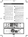
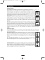
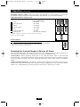
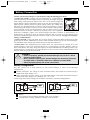
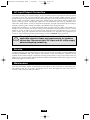
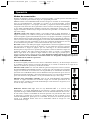
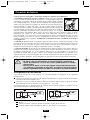
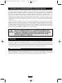
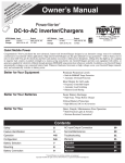
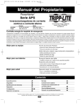
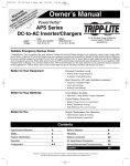
200604211 APS700HF.qxd
ce
y
nt n han t!
ra atio for a cproduyc
r
a
W istr todayp Lite arrant
g ne rip /w
Re r on-lRi EE Tite.com
te F pl
gis a trip
Re win ww.
to w
6/2/2006
1:53 PM
Page 1
Owner’s Manual
PowerVerter®
DC-to-AC
Inverter/Charger
Model: APS700HF
Invert:
Charge:
Input
12 VDC
120V, 60 Hz. AC
Output
120V, 60 Hz. AC
12 VDC
1111 W. 35th Street, Chicago, IL 60609 USA
Customer Support: (773) 869-1234
www.tripplite.com
Reliable Emergency Backup Power
Congratulations on your purchase of the PowerVerter® APS700HF Inverter/Charger! The APS700HF
gives you a convenient, reliable source of AC electricity anywhere and anytime you need it. It keeps
connected equipment up and productive through all utility power problems (blackouts, brownouts and
high voltages) by inverting DC power from user-supplied batteries into AC power. When utility power
is present, the APS700HF automatically passes through power to your equipment while simultaneously
recharging your connected battery bank. Built-in surge suppression provides connected equipment with
additional protection. The APS700HF is the clean, quiet emergency backup power alternative to gas
generators—with no fuel, fumes, or noise to deal with!
Better for Your Equipment
Premium Protection Levels
• Built-In Isobar® Surge Protection
• Automatic Overload Protection
Ideal Output for All Loads
• Frequency-Controlled Output
Better for Your Batteries
Faster Battery Recharge
• High-Amp, 3-Stage Battery Charger
Critical Battery Protection
• High-Efficiency DC-to-AC Inversion
Better for You
Simple, Maintenance-Free Operation
• Multi-Function Lights & Switches
• Moisture-Resistant Construction*
Contents
Specifications/Warranty
2A
Mounting
8A
Safety
3A
Battery Connection
9A
Feature Identification
4A
AC Input/Output Connection
10 A
Operation
5-6 A
Service and Maintenance
10 A
Battery Selection
7A
Troubleshooting
11 A
Español
* Inverter/Chargers are moisture-resistant, not waterproof.
Copyright © 2006. All rights reserved. PowerVerter® is a registered trademark of Tripp Lite.
12 A
200604211 APS700HF.qxd
6/2/2006
1:53 PM
Page 2
Specifications
Model:
APS700HF
AC Input Connection:
Input Cord (NEMA 5-15P)
AC Output Connection:
1 x NEMA 5-15R
Battery Connection:
Hardwire
Inverter
Continuous Power (@ 20° C)
700W/700VA
DC Input Volts (Nominal)
12 VDC
DC Input Voltage Range
10-15 VDC
Minimum DC Fuse Rating
150 A
DC Input Current @Nominal V DC Full Load:
72 A
Battery Charger
Input Volts:
120 VAC
Charging Capacity DC:
6A
Line VAC Operation
Total Input AC Current (Continuous, Charger at Maximum): 8.4 A
Maximum Output Current (Continuous):
5.8 A
Battery Wiring
For maximum efficiency, keep battery wires as short as possible. For very short runs, 6-gauge wiring
may be adequate; for longer runs, 4- or 2-gauge wiring is recommended.
Note: Acceptable power is directly dependent on wire length, i.e. the shorter the wiring, the better the
performance. Total wiring length is the sum of the positive and negative wiring lengths.
Note on Labeling
Two symbols are used on the APS labels.
V~: AC Voltage
: DC Voltage
Limited Warranty
Tripp Lite warrants its Inverter/Chargers to be free from defects in materials and workmanship
for a period of one year (except for outside of U.S.A., Canada and Mexico—120 days) from the
date of retail purchase by end user
Tripp Lite’s obligation under this warranty is limited to repairing or replacing (at its sole option)
any such defective products. To obtain service under this warranty you must obtain a Returned
Material Authorization (RMA) number from Tripp Lite or an authorized Tripp Lite service center.
Products must be returned to Tripp Lite or an authorized Tripp Lite service center with
transportation charges prepaid and must be accompanied by a brief description of the problem
encountered and proof of date and place of purchase. This warranty does not apply to
equipment which has been damaged by accident, negligence or misapplication or has been
altered or modified in any way, including opening of the unit’s casing for any reason. This
warranty applies only to the original purchaser who must have properly registered the product
within 10 days of retail purchase.
EXCEPT AS PROVIDED HEREIN, TRIPP LITE MAKES NO WARRANTIES, EXPRESS OR
IMPLIED, INCLUDING WARRANTIES OF MERCHANTABILITY AND FITNESS FOR A
PARTICULAR PURPOSE. Some states do not permit limitation or exclusion of implied
warranties; therefore, the aforesaid limitation(s) or exclusion(s) may not apply to the purchaser.
EXCEPT AS PROVIDED ABOVE, IN NO EVENT WILL TRIPP LITE BE LIABLE FOR DIRECT,
INDIRECT, SPECIAL, INCIDENTAL OR CONSEQUENTIAL DAMAGES ARISING OUT OF
THE USE OF THIS PRODUCT, EVEN IF ADVISED OF THE POSSIBILITY OF SUCH
DAMAGE. Specifically, Tripp Lite is not liable for any costs, such as lost profits or revenue, loss
of equipment, loss of use of equipment, loss of software, loss of data, costs of substitutes,
claims by third parties, or otherwise.
Tripp Lite has a policy of continuous improvement. Specifications are subject to change without
notice. This product designed and engineered in the USA.
2A
Warranty
Registration
Visit
www.tripplite.com/
warranty today to
register the
warranty for your
new Tripp Lite
product. You’ll be
automatically
entered into a
drawing for a
chance to win a
FREE Tripp Lite
product!*
* No purchase necessary.
Void where prohibited.
Some restrictions apply.
See website for details.
200604211 APS700HF.qxd
6/2/2006
1:53 PM
Page 3
Important Safety Instructions
SAVE THESE INSTRUCTIONS!
This manual contains important instructions and warnings that should be followed during the
installation, operation and storage of all Tripp Lite Inverter/Chargers.
Location Warnings
• Install your Inverter/Charger (whether for a stationary or mobile application) in a location or
compartment that minimizes exposure to heat, dust, direct sunlight and moisture.
• Although your Inverter/Charger is moisture resistant, it is NOT waterproof. Flooding the unit with
water will cause it to short circuit and could cause personal injury due to electric shock. Never
immerse the unit, and avoid any area where standing water might accumulate. Mounting should be
in the driest location available.
• Leave a minimum of 2" clearance at front and back of the Inverter/Charger for proper ventilation.
The heavier the load of connected equipment, the more heat will be generated by the unit.
• Do not install the Inverter/Charger directly near magnetic storage media, as this may result in data
corruption.
• Do not install near flammable materials, fuel or chemicals.
Battery Connection Warnings
• Multiple battery systems must be comprised of batteries of identical voltage, age, amp-hour
capacity and type.
• Because explosive hydrogen gas can accumulate near batteries if they are not kept well ventilated,
your batteries should not be installed in a “dead air” space. Ideally, any space would have some
ventilation to outside air.
• Sparks may result during final battery connection. Always observe proper polarity as batteries are
connected.
• Do not allow objects to contact the two DC input terminals. Do not short or bridge these terminals
together. Serious personal injury or property damage could result.
Equipment Connection Warnings
Do not use a Tripp Lite APS Inverter/Charger in life support or healthcare applications
where a malfunction or failure of a Tripp Lite APS Inverter/Charger could cause failure of
or significantly alter the performance of, a life support device or medical equipment.
• Do not modify the Inverter/Charger’s plug or receptacle in a way that eliminates its ground
connection. Do not use power adapters that will eliminate the plug’s ground connection.
• Connect your Inverter/Charger only to a properly grounded AC power outlet. Do not plug the unit
into itself; this will damage the device and void your warranty.
• You may experience uneven performance results if you connect a surge suppressor, line
conditioner or UPS system to the output of the Inverter/Charger.
Operation Warnings
• Your Inverter/Charger does not require routine maintenance. Do not open the device for any
reason. There are no user serviceable parts inside.
• Potentially lethal voltages exist within the Inverter/Charger as long as the battery supply and/or AC
input are connected. During any service work, the battery supply and AC input connection should
therefore be disconnected.
• Do not connect or disconnect batteries while the Inverter/Charger is operating in either inverting or
charging mode; dangerous arcing may result. Place the Operating Mode Switch in the DC OFF
position before connecting or disconnecting batteries.
3A
200604211 APS700HF.qxd
6/2/2006
1:54 PM
Page 4
Feature Identification
Identify the premium features on your specific model and quickly locate instructions on how to
maximize their use.
1 Operating Mode Switch: controls
Inverter/Charger operation. When this
switch is set to AUTO, connected equipment
receives constant, uninterrupted utility AC
power, with simultaneous charging of
connected batteries. The CHARGE ONLY
setting prevents unwanted battery rundown
when there is no need for battery backup.
Connected batteries are recharged. When the
Operating Mode Switch is set to DC OFF,
both the inverter and the battery charger are
shut off. However, the unit will still pass
utility AC power to connected equipment if
it is plugged into an AC outlet.
2 Operation Indicator Lights: These
intuitive “traffic light” signals show whether
the Inverter/Charger is operating from AC
line power or from DC battery power. They
also signal an alert if the connected
equipment load is too high. See Page 5A for
details.
3 Battery Indicator Lights: These “traffic
light” signals show the approximate charge
level of your battery. See page 6A for details.
4 AC Input Cord: Connects the Inverter/
Charger to any source of utility- or
generator-supplied AC power. See page 10A
for connection instructions. (Cord not
shown.)
5 AC Receptacle: Permits connection of
equipment that would normally be plugged
into a utility outlet. Note: The unit will
always pass AC power to connected
equipment if plugged into a live AC outlet,
regardless of the position of the Operating
Mode Switch.
6 Resettable Circuit Breaker: Protects the
Inverter/Charger against damage due to
overload. See page 6A for resetting
instructions.
7 Low Line Set Dial: Adjusts the AC input
voltage at which the Inverter/Charger will
switch from utility AC power to inverted
battery power. If this dial is set fully
counterclockwise, the unit will allow AC
input to drop to approximately 85V before
switching to inverter mode. Note: The unit
will continue to pass lower-voltage AC
utility power to connected equipment
until the unit switches to inverter mode.
8 DC Power Terminals: Connect to your
battery terminals with user-supplied cabling.
See page 9A for connection instructions.
9 Cooling
Fan:
Regulates
internal
temperature and prolongs equipment service
life. Fan runs intermittently depending on
temperature and load.
10 Main Ground Lug: Properly grounds the
Inverter/Charger to earth ground or vehicle
grounding system. See page 9A for
connection instructions.
3
1
7
2
10
6
5
4
10
9
8
4A
200604211 APS700HF.qxd
6/2/2006
1:54 PM
Page 5
Operation
Switch Modes
After configuring, mounting and connecting your Inverter/Charger, you are able to operate it by
switching between the following operating modes as appropriate to your situation:
AUTO: Switch to this mode when you need constant, uninterrupted AC power for
connected appliances and equipment. The Inverter/Charger will supply AC power to
connected equipment and charge your connected batteries while utility or generatorsupplied AC power is present. Since the inverter is ON (but in Standby) in this mode, it will
automatically switch to battery to supply AC power to connected equipment in the absence
of a utility/generator source or in over/under-voltage situations.
CHARGE ONLY: Switch to this mode when you are not using connected appliances and
equipment in order to conserve battery power by disabling the inverter. The
Inverter/Charger will continue to supply AC power to connected equipment and charge
connected batteries while utility- or generator-supplied AC power is present. However,
since the inverter is OFF in this mode, it WILL NOT supply AC power to
connected equipment in the absence of a utility/generator source or in over/under voltage
situations.
DC OFF: Switch to this mode to shut down the Inverter/Charger completely. This prevents
the inverter from drawing power from the batteries. Use this mode to automatically reset
the unit if it shuts down due to overload or overheating. First remove the excessive load or
allow the unit to sufficiently cool, as applicable. Switch to DC OFF, then back to AUTO or
CHARGE ONLY as desired. If the unit fails to reset, remove more load or allow unit to
cool further and try again. Note: The unit will always pass AC power to connected
equipment if plugged into a live AC outlet, regardless of the position of the Operating Mode
Switch.
Indicator Lights
Your Inverter/Charger features a set of intuitive, user-friendly indicator lights. These easy-to-read
“traffic light” signals allow you to determine at a glance the charge condition of your batteries, operating
details and fault conditions.
LINE Green Indicator: If the operating mode switch is set to AUTO, this light will
ILLUMINATE CONTINUOUSLY while connected equipment is receiving continuous AC
power from a utility/generator source. If the operating mode switch is set to CHARGE
ONLY, this light will FLASH to alert you that the unit's inverter is OFF and will NOT
supply AC power in the absence of a utility/generator source or in over/under-voltage
situations.
INV (Inverting) Yellow Indicator: This light will ILLUMINATE CONTINUOUSLY
while connected equipment is receiving battery-supplied, inverted AC power (i.e. in the
absence of a utility/generator source or in over/under-voltage situations).
LOAD Red Indicator: This red light will FLASH if the inverter is functioning, and the
power demanded by connected appliances and equipment exceeds load capacity. It will
also FLASH due to inverter overheating. If this happens, turn the operating mode switch to
DC OFF, remove the overload and allow the inverter to cool. After the unit has adequately
cooled, you may turn the operating mode switch to either AUTO or CHARGE ONLY. This
light will be DARK when AC power is supplying the load.
5A
200604211 APS700HF.qxd
Operation
6/2/2006
1:54 PM
Page 6
(continued)
BATTERY Indicator Lights: These three lights will illuminate in several sequences to show the
approximate charge level of your connected battery bank and alert you to two fault conditions:
Approximate Battery Charge Level*
Indicator Illuminated
Battery Capacity
(Charging/Discharging)
1
2
3
4
5
6
7
Green
Green & Yellow
Yellow
Yellow & Red
Red
All three lights off
Flashing red
~ 91%–Full
~ 81%–90%
~ 61%–80%
~ 41%–60%
~ 21%–40%
~ 1%–20%
~ 0% (Inverter shutdown)
1
2
3
4
5
6
* Charge levels listed are approximate. Actual conditions vary depending
on battery condition and load.
Fault Condition
Indicator Illuminated
1 All three lights flash quickly*
7
Fault Condition
Overcharge (Charger shutdown)
* Approximately ¼ second on, ¼ second off. May also indicate a battery
charger fault exists. See Troubleshooting section.
1
Resetting Your Inverter/Charger to Restore AC Power
Your Inverter/Charger may cease supplying AC power or DC charging power in order to protect itself
from overload or to protect your electrical system. To restore normal functioning:
Overload Reset: Switch operating mode switch to DC OFF and remove some of the connected
electrical load (i.e. turn off some of the AC devices drawing power which may have caused the overload
of the unit). Wait one minute, then switch operating mode switch back to either AUTO or CHARGE
ONLY.
Output Circuit Breaker Reset: Alternatively, check the unit's output circuit breaker. If it has tripped,
remove some of the electrical load, wait one minute to allow components to cool, and reset the circuit
breaker. See “Troubleshooting” for other possible reasons why AC output may be absent.
6A
200604211 APS700HF.qxd
6/2/2006
1:54 PM
Page 7
Battery Selection
Match Battery Amp-Hour Capacity to Your Application
Select a battery or system of batteries that will provide your Inverter/Charger with proper DC voltage
and an adequate amp-hour capacity to power your application. Even though Tripp Lite Inverter/Chargers
are highly efficient at DC-to-AC inversion, their rated output capacities are limited by the total amphour capacity of connected batteries plus the output of an alternator when one is used.
Example
• STEP 1) Determine Total Wattage Required
Add the wattage ratings of all equipment you will
connect to your Inverter/Charger. Wattage ratings
are usually listed in equipment manuals or on
nameplates. If your equipment is rated in amps,
multiply that number times AC utility voltage to
estimate watts. (Example: a ¼ in. drill requires
2½ amps. 2½ amps × 120 volts = 300 watts.)
Tools
¼" Drill
300W
Cordless Tool
Charger
Orbital Sander
+
NOTE: Your Inverter/Charger will operate at higher efficiencies
at about 75% - 80% of nameplate rating.
220W
+
20W
= 540W
Appliances
Blender
300W
Color TV
+
140W
• STEP 2) Determine DC Battery Amps Required
Divide the total wattage required (from step 1, above) by the battery
voltage to determine the DC amps required.
Laptop Computer
+
100W
= 540W
540 watts ÷ 12V =
45 DC Amps
• STEP 3) Estimate Battery Amp-Hours Required
Multiply the DC amps required (from step 2, above) by the number of
hours you estimate you will operate your equipment exclusively from
45 DC Amps ×
battery power before you have to recharge your batteries with utility2 Hrs. Runtime ×
or generator-supplied AC power. Compensate for inefficiency by 1.2 Inefficiency Rating =
multiplying this number by 1.2. This will give you a rough estimate of
108 Amp-Hours
how many amp-hours of battery power (from one or several batteries)
you should connect to your Inverter/Charger.
NOTE: Battery amp-hour ratings are usually given for a 20-hour discharge rate. Actual amphour capacities are less when batteries are discharged at faster rates. For example, batteries
discharged in 55 minutes provide only 50% of their listed amp-hour ratings, while batteries
discharged in 9 minutes provide as little as 30% of their amp-hour ratings.
• STEP 4) Estimate Battery Recharge Required,
Given Your Application
You must allow your batteries to recharge long enough to replace the
charge lost during inverter operation or else you will eventually run
108 Amp-Hours ÷
down your batteries. To estimate the minimum amount of time you
6 Amps
need to recharge your batteries given your application, divide your
required battery amp-hours (from step 3, above) by your Inverter/Charger Rating =
18 Hours Recharge
Inverter/Charger’s rated charging amps (see Specifications section).
NOTE: For Tripp Lite Inverter/Chargers providing 1000 watts or less of continuous AC power,
a full-size battery will normally allow sufficient power for many applications before
recharging is necessary. For mobile applications, if a single battery is continuously fed by an
alternator at high idle or faster, then recharging from utility or generator power may not be
necessary. Tripp Lite Inverter/Chargers will provide adequate power for ordinary usage
within limited times without the assistance of utility or generator power. However, when
operating extremely heavy electrical loads at their peak in the absence of utility power, you
may wish to “assist your batteries” by running an auxiliary generator or vehicle engine, and
doing so at faster than normal idling.
7A
200604211 APS700HF.qxd
6/2/2006
1:54 PM
Page 8
Mounting
WARNING! Mount your Inverter/Charger BEFORE DC
battery and AC power connection. Failure to follow these
instructions may lead to personal injury and/or damage
to the Inverter/Charger and connected systems.
Tripp Lite recommends that you permanently mount your Inverter/Charger in the configuration
illustrated below. The APS700HF features integral mounting brackets on the front and rear of the unit.
The user must supply mounting hardware and is responsible for determining if hardware and mounting
surface are adequate to support the weight of the unit. See page 3A for location warnings and cautions.
Using the measurements as shown in the diagram install two user-supplied fasteners A , leaving the
heads slightly raised. Slide the unit over the fasteners to engage the mounting bracket slots B . Tighten
fasteners. Install two additional fasteners C over the remaining mounting bracket.
C
10.93 in. (27.8 cm.)
B
4.31 in.
(10.95 cm.)
A
8A
200604211 APS700HF.qxd
6/2/2006
1:54 PM
Page 9
Battery Connection
Connect your Inverter/Charger to your batteries using the following procedures:
• Connect DC Wiring: Though your Inverter/Charger is a high-efficiency
converter of electricity, its rated output capacity is limited by the length and gauge
of the cabling running from the battery to the unit. Use the shortest length and
largest diameter cabling (maximum 2 gauge) to fit your Inverter/Charger’s DC
Input terminals. Shorter and heavier gauge cabling reduces DC voltage drop
and allows for maximum transfer of current. Your Inverter/Charger is capable
of delivering peak wattage at up to 175% of its rated continuous wattage output
for brief periods of time. See Specifications page for details. Heavier gauge
DC Connectors
cabling should be used when continuously operating heavy draw equipment
under these conditions. Tighten your Inverter/Charger and battery terminals to approximately 3.5
Newton-meters of torque to create an efficient connection and to prevent excessive heating at this
connection. Insufficient tightening of the terminals could void your warranty. See page 2A for battery
wiring recommendations.
• Connect Ground: Using a #8 AWG wire or larger directly connect the Main Ground Lug to earth
ground. See the Feature Identification section to locate the Main Ground Lug on your Inverter/Charger.
All installations must comply with national and local codes and ordinances.
• Connect Fuse: NEC (National Electrical Code) article 551 requires that you connect all of your
Inverter/Charger’s positive DC Terminals directly to a UL-listed fuse(s) and fuse block(s) within 18
inches of the battery. The fuse’s rating must equal or exceed the Minimum DC Fuse Rating listed in your
Inverter/Charger’s specifications. See Specifications for fuse and fuse block recommendations. See
diagrams below for proper fuse placement.
WARNING!
• Failure to properly ground your Inverter/Charger may result in a lethal
electrical shock hazard.
• Never attempt to operate your Inverter/Charger by connecting it directly
to output from an alternator rather than a battery or battery bank.
• Observe proper polarity with all DC connections.
Battery Configuration
You may connect one or more batteries to your Inverter/Charger in either of the following
configurations.
1 Parallel connection: The voltage of each connected battery must match the Inverter/Charger's
Nominal DC Input Voltage (12V).
2 Series connection: The total voltage of all connected batteries must match the Inverter/Charger's
Nominal DC Input Voltage (12V). Example: 6V + 6V = 12V.
Contact Tripp Lite technical support for assistance with battery connection configurations.
A
A
12 Volts
6 Volts
APS700HF
12 Volts
B
C
B
2 Series Connection
1 Parallel Connection
A
B
C
Battery
UL-Listed Fuse & Fuse Block (mounted within 18 in. of battery)
Large-Diameter Cabling, Maximum 2 Gauge, to Fit Terminals
9A
APS700HF
6 Volts
C
200604211 APS700HF.qxd
6/2/2006
1:54 PM
Page 10
AC Input/Output Connection
To avoid overloading your Inverter/Charger, be sure to match the power requirements of the equipment
you plan to run at any one time (add their total watts) with the output wattage capacity of your
Inverter/Charger (see Specifications section). When figuring the power requirements of your equipment,
do not confuse “continuous” wattage with “peak” wattage ratings. Most electric motors require more
power at start-up (“peak” wattage) than required to run continuously after start-up, sometimes over
100% more. Some motors, such as in refrigerators and pumps, start and stop intermittently according to
demand, requiring “peak” wattage at multiple, unpredictable times during operation.
Plug the Inverter/Charger’s AC input cord into an outlet providing 120V AC, 60Hz. power. Make sure
that the circuit you connect your Inverter/Charger to has adequate overload protection, such as a circuit
breaker or a fuse. To make use of AC output (either utility/generator pass-through power or inverter
power) simply plug your equipment into the Inverter/Charger's AC receptacle. Any equipment you
connect to it will benefit from your Inverter/Charger’s built-in ISOBAR® surge protection!
Warning! Consult a qualified electrician and follow all
applicable electrical codes and requirements for hardwire
connection. Disconnect both DC input and AC utility supply
before attempting hardwiring.
Service
If you are returning your Inverter/Charger to Tripp Lite, please pack it carefully, using the ORIGINAL
PACKING MATERIAL that came with the unit. Enclose a letter describing the symptoms of the
problem. If the Inverter/Charger is within the warranty period, enclose a copy of your sales receipt. To
obtain service you must obtain a Returned Material Authorization (RMA) number from Tripp Lite or an
authorized Tripp Lite service center.
Maintenance
Your Inverter/Charger requires no maintenance and contains no user-serviceable or replaceable parts,
but should be kept dry at all times. Periodically check, clean and tighten all cable connections as
necessary, both at the unit and at the battery.
10 A
200604211 APS700HF.qxd
6/2/2006
1:54 PM
Page 11
Troubleshooting
Try these remedies for common Inverter/Charger problems before calling for assistance. Call Tripp Lite
Customer Service at (773) 869-1234 before returning your unit for service.
Battery Indicator Lights
Operating Mode Switch
Operation Indicator Lights
SYMPTOM
PROBLEMS
CORRECTIONS
No AC Output
(All Indicator Lights Are OFF)
Unit is not properly connected
to utility power.
Connect unit to utility power.
Circuit breaker is tripped.
Reset circuit breaker.
Battery Not Recharging
Connected batteries are dead.
Check and replace old batteries.
(AC Input Present)
Battery fuse* is blown.
Check and replace fuse.*
Battery cabling* is loose.
Check and tighten or replace cabling.*
Unit has shut down due to battery
overcharge (preventing battery
damage). The problem may be
with connected auxiliary chargers,
if any, or with the unit’s charger.
Disconnect any auxiliary chargers.
Reset by moving Operating Mode
Switch to “DC OFF.” Wait 1 minute
and switch to “AUTO” or “CHARGE
ONLY.” If unit remains in shutdown
mode after several attempts to reset,
contact Tripp Lite Customer Service
for assistance.
All Three Battery Indicator Lights Battery is overcharged. Unit will
Are Rapidly Flashing
shut down to prevent battery
(¼ Second Flashes)
damage. The problem may be
with connected auxiliary chargers,
if any, or with the unit’s charger.
Disconnect any auxiliary chargers.
Reset by moving Operating Mode
Switch to “DC OFF.” Wait 1 minute
and switch to “AUTO” or “CHARGE
ONLY.” If unit remains in shutdown
mode after several attempts to reset,
contact Tripp Lite Customer Service
for assistance.
Red “LOW” Battery
Indicator Light is Flashing
Battery voltage is low. Unit will
automatically shut down after 10
seconds to protect battery from
damage.
Make sure that AC power is present
in order to recharge batteries. Must
be set to Operating Mode Switch
“AUTO” or “CHARGE ONLY.”
False reading due to undersized
or insufficiently connected
DC cabling.
Use sufficient size DC cable
sufficiently connected to the
Inverter/Charger.
Inverter is overloaded. Unit will
automatically shut down after
5 seconds.
Reduce load. Operating Mode
Switch must be set to "AUTO"
or "CHARGE ONLY."
Red “LOAD” Operation
Indicator Light Flashing
* User-supplied.
11 A
200604211 APS700HF.qxd
6/2/2006
1:54 PM
Page 12
Manual del Propietario
PowerVerter®
Corriente directa (DC) a
Corriente alterna (AC)
Inversor/Cargador
Modelo: APS700HF
Inversión:
Carga:
1111 W. 35th Street, Chicago, IL 60609 USA
Soporte al cliente: (773) 869-1234
www.tripplite.com
Entrada
Salida
12 VDC
120V, 60 Hz. VAC
120V, 60 Hz. AC 12 VDC
Confiable reserva de energía de emergencia
¡Felicidades por haber comprado el inversor/cargador PowerVerter® APS700HF! El APS700HF le
ofrece una fuente de electricidad AC confiable y a su alcance dondequiera y en el momento que la
necesite. Permite que los equipos se mantengan funcionando y productivos en medio de cualquier
problema de energía que pueda surgir (apagones y caídas y aumentos del voltaje) invirtiendo la corriente
DC proveniente de las baterías a energía AC. Cuando hay energía de la red comercial, el APS700HF la
transfiere automáticamente a sus equipos al tiempo que recarga simultáneamente las baterías que están
conectadas. El supresor de picos de voltaje que trae incorporado les brinda protección extra a los
equipos conectados El APS700HF es la alternativa de energía de reserva limpia y silenciosa en lugar de
las plantas eléctricas. ¡Sin humo, sin combustible y sin ruidos molestosos!
Mejor para su equipo
Niveles de protección Premium
• Protección contra sobretensiones integrada Isobar®
• Protección automática de sobrecarga
Salida ideal para cualquier carga
• Salida controlada por frecuencia
Mejor para sus baterías
Recarga de baterías más rápida
• Cargador de baterías de 3 etapas de alta capacidad
Protección crítica de batería
• Inversión de CC a CA de alta eficiencia
Mejor para usted
Operación simple, sin mantenimiento
• Luces y conmutadores multifunción
• Fabricación resistente a la humedad*
Contenido
Especificaciones
Garantía
Seguridad
Identificación de funciones
Operación
Selección de baterías
13 A
14 A
15 A
16 A
17-18 A
19 A
Montaje
Conexión de la batería
Conexión de entrada/salida
de corriente alterna
Servicio/Mantenimiento
Solución de problemas
English
20 A
21 A
22 A
22 A
23 A
1A
* Los inversores/cargadores son resistentes a la humedad, pero no son impermeables.
Copyright © 2006. Todos los derechos reservados. PowerVerter® es una marca comercial registrada de Tripp Lite.
200604211 APS700HF.qxd
6/2/2006
1:54 PM
Page 13
Especificaciones
Modelo:
Conexión de entrada de CA:
Conexión de salida de CA:
Conexión de batería:
Inversor
Energía continua (a 20º C):
Voltios CC de entrada (Nominal):
Rango de voltaje de CC de entrada:
Mínima capacidad fusible CC:
Corriente CC de entrada a Voltaje nominal de CC plena carga:
Cargador de batería
Voltios de entrada:
Capacidad de carga CC:
Operación de Línea VCA
Corriente alterna total de entrada
(Continua, cargador al máximo):
Máxima salida corriente (continua):
APS700HF
Cordón de alimentación
(NEMA 5-15P)
1 x NEMA 5-15R
Cableado
700W/700VA
12 VCC
10-15 VCC
150 A
72 A
12 VCC
6A
8.4 A
5.8 A
Cableado de la batería
Para obtener una máxima eficiencia, mantenga los cables de las baterías tan cortos como sea posible.
Para tendidos muy cortos, el cable de calibre 6 es adecuado; para tendidos mayores, se recomienda
usar un cable de calibre 4- o 2-.
Nota: La energía admisible depende directamente de la longitud del cable; es decir, cuanto más corto
el cable, mayor el rendimiento. La longitud total del cable es la suma de las longitudes del cable
positivo y el cable negativo.
Nota sobre el rotulado
Se usan dos símbolos en las etiquetas
APS. V~: Voltaje CA
: Voltaje CC
13 A
200604211 APS700HF.qxd
6/2/2006
1:54 PM
Page 14
Garantía limitada
Tripp Lite garantiza que su inversor/cargador está libre de defectos en materiales y mano de obra por un período de un año
(excepto fuera de EE.UU., Canadá y México-120 días) desde la fecha de compra por parte del usuario final.
Bajo esta garantía, la obligación de Tripp Lite está limitada a reparar o reemplazar (a su opción) cualquier producto
defectuoso. Para obtener servicio bajo esta garantía, debe conseguir un número de Autorización de devolución de mercadería
(RMA) de Tripp Lite o de un centro de servicio autorizado de Tripp Lite. Los productos deben ser devueltos a Tripp Lite o a un
centro de servicio autorizado de Tripp Lite con los cargos de transporte pagados por adelantado y deben estar acompañados
de una breve descripción del problema encontrado y un comprobante de la fecha y el lugar de compra. Esta garantía no se
aplica al equipo que ha sido dañado por accidente, negligencia o uso inadecuado, o que ha sido alterado o modificado en
cualquier forma, incluyendo la abertura de la caja de la unidad por cualquier motivo. Esta garantía solamente se aplica al
comprador original que debe haber registrado correctamente el producto dentro de los 10 días de la compra.
SALVO POR LO ESTABLECIDO EN ESTE DOCUMENTO, TRIPP LITE NO EXPRESA NINGUNA GARANTÍA, EXPRESA O
IMPLÍCITA, INCLUYENDO GARANTÍAS DE COMERCIABILIDAD O IDONEIDAD PARA UN PROPÓSITO PARTICULAR.
Algunos estados no permiten limitaciones o exclusiones de las garantías implícitas; por lo tanto, las limitaciones o exclusiones
mencionadas anteriormente pueden no aplicarse al comprador.
SALVO POR LO ESTABLECIDO ARRIBA, EN NINGÚN CASO TRIPP LITE SERÁ RESPONSABLE POR DAÑOS
DIRECTOS, INDIRECTOS, ESPECIALES, INCIDENTALES O EMERGENTES, RESULTANTES DEL USO DE ESTE
PRODUCTO, AUN EN EL CASO DE HABERSE INFORMADO DE LA POSIBILIDAD DE DICHOS DAÑOS. Específicamente,
Tripp Lite no es responsable por ningún costo, como pérdida de ingresos o beneficios, pérdida de equipos, pérdida de uso
de equipos, pérdida de software, pérdida de datos, costos por reemplazos, reclamaciones de terceras partes, o lo que
corresponda.
Tripp Lite tiene una política de mejoramiento continuo. Las especificaciones están sujetas a cambio sin previo aviso. Este
producto ha sido creado y diseñado en EE.UU.
LEA SU INSTRUCTIVO
CONSULTE SUS CONDICIONES DE GARANTÍA POR PRODUCTO
PÓLIZA DE GARANTÍA
Este equipo marca Tripp Lite, modelo _______________ está garantizado por TRIPP LITE, que tiene su domicilio en la calle
de Sierra Candela No.111-107, Col Lomas de Chapultepec, CP 11000, México, DF, y puede hacer efectiva su garantía así
como obtener partes, componentes, consumibles y accesorios en el Centro de Servicio Q PLUS ubicado en Av Coyoacan
931, Col. Del Valle, C.P. 03120 México. D.F., tel. 50 00 27 00 contra cualquier defecto de fabricación y funcionamiento,
imperfecciones de materiales, piezas, componentes y mano de obra al consumidor acorde a la siguiente tabla:
Producto
Sistema de Energía Ininterrumpible (UPS)
Sistema de Energia Ininterrumpible (UPS)
Regulador y Acondicionador de Tension
Inversores
Multiplexor y Conmutador
Conmutador
Supresor de Picos de Tensión
Modelo
Familia: BC, OMNI, SMART, SMART
ONLINE MONOFASICOS
Familia: SMART ONLINE 3PH
Familia: LS, LC
Familia: APS, PV
Familia: KVM
Modelo: B020-016
Familia: PROTECT IT, ISOBAR
Vigencia
2Años
1 Año
2 Años
2 Años
5 Años
6 Meses
25 Años
CONDICIONES
1. Para hacer válida su garantía no podrán exigirse mayores requisitos que la presentación de esta póliza debidamente
llenada y sellada por el establecimiento que lo vendió junto con el producto en el lugar donde fue adquirido.
2. TRIPP LITE, se compromete a reparar, y en caso de que a su juicio no sea posible la reparación, a cambiar el equipo, así
como las piezas y componentes defectuosos del mismo sin cargo alguno para el propietario durante el periodo de
garantía, así como los gastos de transportación razonablemente erogados del producto que deriven de su cumplimiento,
dentro de su red de servicio.
3. El tiempo de reparación en ningún caso será mayor de 30 días contados a partir de la fecha de recepción del producto en
el Centro Autorizado de Servicio, en donde también podrán adquirir refacciones y partes.
4. En caso de que la presente póliza de garantía se extraviara, el consumidor puede recurrir a su proveedor para que expida
un duplicado de la póliza de garantía, previa presentación de la nota de compra o factura correspondiente.
EXCLUSIONES
Esta garantía no es válida en los siguientes casos:
a) Cuando el producto se hubiese utilizado en condiciones distintas a la normales.
b) Cuando el producto no hubiese sido operado de acuerdo con el instructivo de uso que se le acompaña.
c) Cuando el producto hubiese sido alterado o reparado por personas no autorizadas por el fabricante nacional,
importador o comercializador responsable respectivo.
Este equipo fue vendido por: _____________________________________
con domicilio en ________________________________________________
el día _____ de ___________ de ________, fecha a partir de la que inicia la presente garantía.
14 A
200604211 APS700HF.qxd
6/2/2006
1:54 PM
Page 15
Instrucciones de seguridad importantes
¡GUARDE ESTAS INSTRUCCIONES!
Este manual contiene instrucciones y advertencias importantes que deben seguirse durante la
instalación, operación y almacenamiento de todos los inversores/cargadores de Tripp Lite.
Advertencias de ubicación
• Instale su inversor/cargador (ya sea para una aplicación estacionaria o móvil) en un lugar o
compartimiento que minimice la exposición al calor, al polvo, a la luz solar directa y a la humedad.
• Aunque su inversor/cargador es resistente a la humedad, NO es impermeable. Llenar la unidad con
agua causará un cortocircuito y podría causar lesiones personales por choque eléctrico. Nunca
sumerja la unidad, y evite cualquier área donde pueda acumularse agua. El montaje debe realizarse
en la ubicación más seca disponible.
• Deje una luz mínima de 5 cm (2") en la parte frontal y posterior del inversor/cargador para una
adecuada ventilación. A mayor carga el equipo conectado, la unidad generará más calor.
• No instale el inversor/cargador directamente cerca de medios de almacenamiento magnético, ya
que puede provocar daño a los datos.
• No instale cerca de materiales inflamables, combustible o productos químicos.
Advertencias de conexión de batería
• Los sistemas de baterías múltiples deben estar formados de baterías con un voltaje, una antigüedad,
una capacidad en amperios hora y un tipo idénticos.
• Debido a que puede acumularse gas hidrógeno explosivo cerca de las baterías si no están bien
ventiladas, no debe instalar baterías en un espacio sin circulación de aire. En forma ideal,
cualquier espacio tendría cierta ventilación al exterior.
• Pueden producirse chispas durante la conexión final de la batería. Siempre observe la correcta
polaridad al conectar las baterías.
• No permita que ningún objeto entre en contacto con los dos terminales de entrada de corriente
continua. No ponga en cortocircuito ni en puente estos terminales. Podrían producirse serias
lesiones personales o daños a la propiedad.
Advertencias sobre la conexión de equipos
No use un inversor/cargador Tripp Lite APS para aplicaciones de soporte de vida o cuidado
de la salud, en las que un funcionamiento defectuoso o una falla del inversor/cargador
Tripp Lite pueda causar la falla o una alteración importante en el funcionamiento del
dispositivo médico o de soporte de vida.
• Modelos con cordón: No modifique el enchufe del inversor/cargador ni la toma en una forma en
que elimine su conexión a tierra. No use adaptadores de potencia que eliminen la conexión a tierra
del enchufe.
• Conecte su inversor/cargador sólo a una salida de corriente alterna o a una fuente cableada
adecuadamente puesta a tierra. No conecte la unidad a si misma; esto dañará el dispositivo y
anulará su garantía.
• Puede experimentar un funcionamiento irregular si conecta un supresor de sobretensiones, un
acondicionador de línea o un sistema UPS a la salida del inversor/cargador.
Advertencias de operación
• Su inversor/cargador no requiere un mantenimiento de rutina. No abra el dispositivo por ninguna
razón. No hay partes que requieran man tenimiento por parte del usuario en su interior.
• Existen voltajes potencialmente letales dentro del inversor/cargador, en tanto la alimentación de
baterías y/o la entrada de corriente alterna estén conectadas. En consecuencia, durante cualquier
trabajo de mantenimiento, deben desconectarse la alimentación de baterías y la entra da de
corriente alterna.
• No conecte ni desconecte las baterías mientras el inversor/cargador esté operando en modo de
inversión o de carga; podría producirse un arco peligroso. Coloque el Conmutador de modo de
operación en la posición DC OFF antes de conectar o desconectar baterías.
15 A
200604211 APS700HF.qxd
6/2/2006
1:54 PM
Page 16
Identificación de funciones
Identifica las funciones Superior en su modelo específico y ubica rápidamente las instrucciones para
optimizar su utilización.
1 Conmutador para el modo de operación:
Controla la operación Inversor/Cargador
Cuando este Conmutador está en AUTO, los
equipos conectados al circuito reciben energía
normal AC ininterrumpida, al tiempo que
continúa cargando las baterías. El ajuste
CHARGE ONLY (SÓLO RECARGA) evita
la descarga no deseada de la batería cuando no
hay necesidad de respaldo de batería. Las
baterías conectadas continúan recargándose.
Cuando el Conmutador de modo de operación
está en DC OFF, tanto el inversor como el
cargador de baterías están apagados. Sin
embargo, el aparato aún dejará que la energía
AC comercial pase a los equipos conectados, si
están enchufados a una salida de corriente AC.
2 Luces Indicadoras de operación: Estas
señales intuitivas a modo de “semáforo”
muestran si el Inversor/Cargador está
operando de la línea AC comercial o de la
corriente DC de las baterías. También son la
señal de alerta si la carga de los equipos
conectados al circuito es muy alta. Véase la
página 17 A para más detalles.
3 Luces Indicadoras de las baterías: Estas
“luces de tráfico” le dicen el nivel de carga
aproximado de sus baterías. Véase la página
18 A para más detalles.
4 Cordón de entrada de corriente AC: Sirve
para conectar el Inversor/Cargador a cualquier
fuente de energía AC alimentada por la red
comercial o por un generador. Véase la página
22 A sobre las instrucciones de conexión.
(Cuerda no demostrada.)
5 Receptáculo de corriente AC: Permite
conectar equipos que normalmente se
conectarían a una salida alimentada por
electricidad comercial. Nota: El aparato
6
7
8
9
10
siempre dejará pasar corriente AC al equipo
conectado si está enchufado a un
tomacorriente AC, sin importar la posición del
Conmutador de modo de operación
Conmutador reseteable del circuito:
Protege al Inversor/Cargador contra posibles
daños causados por una sobrecarga. Véase la
página 18 A para las instrucciones de cómo
resetear el aparato.
Selector de línea baja: Regula el voltaje AC
de entrada al que el Inversor/Cargador
cambiará de la corriente comercial a la
corriente invertida de las baterías. Si este
selector se gira completamente en dirección
contraria a las manecillas del reloj, el aparato
permitirá que la corriente de entrada AC caiga
a unos 85V antes de cambiar al modo de
inversor. Nota: El aparato seguirá dejando
pasar corriente comercial AC a bajo voltaje
hacia los equipos conectados hasta que
cambie al modo de inversor.
Terminales de energía de corriente DC:
Conéctese a sus terminales de batería con los
cables suministrados. Véase la página 21 A
para instrucciones de la conexión.
Abanico de enfriamiento: Regula la
temperatura interna y prolonga el tiempo de
vida del aparato. El abanico funciona de
manera intermitente, dependiendo de la
temperatura y la carga
Conector principal de tierra: Conecta
adecuadamente a tierra el Inversor/Cargador,
ya sea al suelo o al sistema de tierra de un
vehículo Véase la página 21 A para
instrucciones de la conexión.
3
1
7
2
10
6
5
4
10
9
8
16 A
200604211 APS700HF.qxd
6/2/2006
1:54 PM
Page 17
Operación
Modos de conmutación
Después de configurar, montar y conectar su Inversor/Cargador, ya puede operarlo alternando entre los
siguientes modos de operación hasta llegar al el apropiado para usted:
AUTO: Cambie a esta modalidad cuando necesite energía AC constante es ininterrumpida
para los electrodomésticos conectados al circuito. El Inversor/Cargador seguirá
suministrando energía AC a los equipos conectados y cargará las baterías mientras haya
energía de la red comercial o de un generador. Como el inversor está ON (pero en Standby)
en este modo, automáticamente cambiará a batería para suministrarles energía AC a los
equipos conectados cuando no haya energía comercial o de generador o en situaciones de
bajo o alto voltaje.
CHARGE ONLY (sólo carga): Cambié a este modo cuando no tenga dispositivos o
equipos conectados y así conserve la energía de las baterías, deshabilitando el inversor. El
Inversor/Cargador seguirá suministrando energía AC a los equipos conectados y cargará las
baterías mientras haya presente energía de la red comercial o de un generador. Sin embargo,
como el inversor está en modo OFF (apagado) en este modo, NO SUMINISTRARÁ energía
AC a los equipos que estén conectados, ya que no hay una fuente de alimentación, sea esta
la red comercial o un generador o está en una situación de bajo o alto voltaje.
DC OFF: Cambie a este modo para apagar completamente el Inversor/Cargador Esto evita
que el inversor extraiga energía de las baterías. Use este modo para resetear el aparato
automáticamente si llegara a apagarse por una sobrecarga o un sobrecalentamiento.
Primero quite la carga excesiva o permita que el aparato se enfríe lo suficiente. Según sea
pertinente. Cambie a DC OFF, entonces póngalo de nuevo en AUTO o en CHARGE
ONLY, según desee. Si el aparato no logra resetearse, retire más carga o permita que el
aparato se enfríe aún más e intente de nuevo. Nota: El aparato siempre dejará pasar corriente AC al
equipo conectado si está enchufado a un tomacorriente AC energizado, sin importar la posición
del Conmutador de Modo de Operación.
Luces indicadoras
Su Inversor/Cargador presenta una serie de luces indicadoras intuitivas y de fácil manejo. Estas luces
de “semáforo” de fácil lectura le permiten determinar de un vistazo la condición de la carga de sus
baterías, los detalles de operación y condiciones de fallo.
Indicador LINE verde: Si el switch de modo de operación está puesto en AUTO, está luz
SE MANTENDRÁ ENCENDIDA mientras el equipo que está conectado esté recibiendo
energía AC continua de la red comercial o de un generador. Si el conmutador de modo de
operación está en CHARGE ONLY, está luz DESTELLARÁ para alertarle que el inversor
del aparato está OFF (apagado) y NO suministrará energía AC si no está siendo alimentado
por la red comercial o un generador, o si hay una situación de bajo o alto voltaje.
Indicador INV (Invirtiendo) amarillo: Está luz SE MANTENDRÁ ENCENDIDA
mientras el equipo conectado esté recibiendo energía AC invertida proveniente de las
baterías (es decir, cuando no está siendo alimentado por la red comercial o un general, o en
caso de un bajo o alto voltaje)
IIndicador LOAD color rojo: Esta luz roja DESTELLARÁ si el inversor está
funcionando, y la energía demandada por los aparatos y equipos conectados excede la
capacidad de carga. También DESTELLARÁ en caso de sobrecalentamiento del inversor.
Si esto sucede, cambie el conmutador de modo de operación a la posición DC OFF, retire
la sobrecarga y permita que el inversor se enfríe. Después de que el aparato se haya
enfriado adecuadamente, puede poner el Conmutador de vuelta en el modo de operación
AUTO o en CHARGE ONLY. Esta luz se APAGARÁ cuando la energía AC esté
suministrando la carga.
17 A
200604211 APS700HF.qxd
Operación
6/2/2006
1:54 PM
Page 18
(continued)
Luces Indicadoras de la BATERÍAS: Esas tres luces alumbrarán en varias secuencias para indicar el
nivel aproximado de carga del conjunto de baterías conectadas y alertarle de dos condiciones de fallas.
Nivel aproximado de carga de batería*
Indicador iluminado
Capacidad de
batería (Carga/Descarga)
1
2
3
4
5
6
7
Verde
Verde y amarillo
Amarillo
Amarillo y rojo
Rojo
Las tres luces apagadas
Rojo destellando
~ 91%-completa
~ 81%-90%
~ 61%-80%
~ 41%-60%
~ 21%-40%
~ 1%-20%
~ 0% (Inversor apagado)
1
2
3
4
5
6
* Los niveles de carga indicados son aproximados. Las condiciones
reales varían en función de la condición y carga de la batería.
Condición de falla
Indicador iluminado
1 Las tres luces destellan
rápidamente*
7
Condición de falla
Sobrecarga
(Cargador apagado)
* Aproximadamente ¼ segundo encendido, ¼ segundo apagado. También puede
indicar una falla del cargador de batería. Vea la sección Solución de problemas.
1
Restableciendo su inversor/cargador para restablecer la energía de
corriente alterna
Su inversor/cargador puede dejar de suministrar energía de corriente alterna o energía de carga de
corriente continua a fin de protegerse a si mismo contra una sobrecarga, o para proteger su sistema
eléctrico. Para restablecer el funcionamiento normal:
Restablecer sobrecarga: Cambie el conmutador de modo de operación a “OFF” y retire algo de la
carga eléctrica conectada (es decir: apague algunos de los dispositivos de corriente alterna que
consumen energía que puedan haber causado la sobrecarga de la unidad) Espere un minuto, y luego
cambie el conmutador de modo de operación otra vez a AUTO o CHARGE ONLY.
Restaurar interruptor automático de salida: En forma alternativa, revise el interruptor automático de
salida del panel frontal de la unidad. Si ha disparado, retire algo de la carga eléctrica y luego espere un
minuto para permitir que se enfríen los componentes antes de restaurar el interruptor automático. Vea la
sección Solución de problemas para otras posibles razones por las que pueda no haber salida de
corriente alterna.
18 A
200604211 APS700HF.qxd
6/2/2006
1:54 PM
Page 19
Selección de batería
Haga coincidir la capacidad en amperios-hora de su batería con su aplicación
Seleccione una batería o sistema de baterías que le proporcionarán a su inversor/cargador un voltaje de
corriente continua adecuado y una capacidad en amperios-hora apropiada a la potencia de su aplicación.
Aun cuando los inversores/cargadores de Tripp Lite son muy eficientes en la inversión de corriente
continua a corriente alterna, sus capacidades de salida están limitadas por la capacidad total en
amperios-hora de las baterías conectadas, más la salida de un alternador si es que se utiliza.
Ejemplo
• PASO 1) Determine la potencia total
requerida
Añada la potencia nominal de todos los equipos
que va a conectar a su inversor/cargador. La
potencia nominal de un equipo normalmente está
indicada en su manual o en su placa. Si su equipo
tiene un valor en amperios, multiplique ese
número por el voltaje en corriente alterna de la red
para calcular los vatios. (Ejemplo: a taladro de ¼"
requiere 2½ amperios 2½ amperios × 120 voltios
= 300 vatios)
Herramientas
Taladro de ¼"
300W
Cargador
inalámbrico
Lijadora orbital
+
220W
+
20W
= 540W
Aparatos
Licuadora
Computadora
portátil
TV Color
NOTA: Su inversor/cargador operará a mayores eficiencias al 75%
- 80%, aproximadamente de su valor de placa.
300W
+
140W
+
100W
= 540W
• PASO 2) Determine la corriente (en amperios) de corriente
continua de batería requerida
540 vatios ÷ 12V =
Divida los vatios totales requeridos (del paso 1, arriba) entre el voltaje de 45 Amperios CC
la batería para determinar los amperios de corriente continua requeridos.
• PASO 3) Estime los amperios-hora de batería requeridos
Multiplique los amperios de corriente continua requeridos (del paso
2, arriba) entre el número de horas que estima usted operará su equipo
exclusivamente con energía de batería antes de que tenga que
45 amps CC ×
recargar sus baterías con energía de corriente alterna suministrada por
2 horas
la red- o por un generador. Compense por ineficiencia multiplicando
funcionamiento ×
este número por 1.2. Esto le dará un estimado grueso de cuantos
amperios-hora de energía de batería (de una o varias baterías) debe 1.2 factor de ineficiencia =
conectar a su inversor/cargador.
108 Amperios-hora
NOTA: La capacidad de amperios-hora de una batería usualmente se da considerando una
descarga de 20 horas. Las capacidades reales de amperios-hora son menores cuando las
baterías están descargando a mayor velocidad. Por ejemplo, baterías descargadas en 55
minutos proporcionan sólo 50% de sus amperios-hora nominales, mientras que las baterías
descargadas en 9 minutos proporcionan apenas 30% de sus amperios-hora nominales.
• PASO 4) Estime la recarga de batería requerida,
considerando su aplicación
Debe permitir que sus baterías se recarguen el tiempo suficiente para
reemplazar la carga perdida durante la operación del inversor, por que
de otro modo sus baterías, eventualmente, se descargarán. Para
estimar la cantidad mínima de tiempo que debe recargar sus baterías,
considerando su aplicación, divida sus amperios-hora de batería
requeridos (del paso 3, arriba) entre los amperios de carga nominales
de su inversor/cargador (vea la sección Especificaciones)
NOTA: Para los inversores/cargadores de Tripp Lite que proporcionan 1000 vatios o menos
de energía de corriente alterna en forma permanente, una batería de tamaño completo
normalmente permitirá suficiente energía para muchas aplicaciones ante de que la recarga
sea necesaria. Para aplicaciones móviles, si una sola batería es alimentada continuamente
por un alternador en alto vacío o más rápido, la recarga con energía de la red o de un
generador puede no ser necesaria. Para inversores/cargadores de Tripp Lite mayores que
1000 vatios usados en aplicaciones móviles, Tripp Lite recomienda usar al menos dos
baterías, si es posible alimentadas por un alternador de servicio pesado siempre que el
vehículo esté funcionando. Los inversores/cargadores Tripp Lite proporcionarán energía
adecuada para uso ordinario por tiempos limitados sin la ayuda de energía de la red o de
un generador. Sin embargo, al operar con cargas eléctricas muy pesadas en sus valores
máximos y en ausencia de energía de la red, puede desear "ayudar a sus baterías" haciendo
funcionar un generador auxiliar o el motor de un vehículo, y hacerlo más rápido que en
operación normal de vacío.
19 A
108 amperios-horas ÷
6 amperios Capacidad
de inversor/cargador =
18 Horas de Recarga
200604211 APS700HF.qxd
6/2/2006
1:54 PM
Page 20
Montaje
¡ADVERTENCIA! Monte su inversor/cargador ANTES de
conectar la batería de corriente continua y la energía de
corriente alterna. No seguir estas instrucciones puede
producir lesiones personales y/o daños al
inversor/cargador y a los sistemas conectados.
Tripp Lite recomienda el montaje permanente de su inversor/cargador en cualquiera de las
configuraciones ilustradas abajo. El modelo APS700HF presenta soportes de montaje integrales en las
partes delantera y posterior de la unidad. El usuario debe suministrar la tornillería de montaje y es
responsable de determinar si la misma y la superficie de montaje son adecuadas para soportar el peso
del inversor/cargador. Vea página 15 A para advertencias de ubicación.
Usando las medidas del diagrama, instale dos tornillos suministrados por el usuario A , dejando las
cabezas ligeramente levantadas. Deslice la unidad hacia atrás sobre los tornillos para enganchar las
ranuras de montaje moldeadas B en la parte inferior del ganinete del inversor/cargador. Instale dos
tornillos adicionales C sobre el quedándose montar paréntesis .
C
10.93 in. (27.8 cm.)
B
4.31 in.
(10.95 cm.)
A
20 A
200604211 APS700HF.qxd
6/2/2006
1:54 PM
Page 21
Conexión de batería
Conecte su inversor/cargador a sus baterías usando los siguientes procedimientos:
• Conexión del cableado de corriente continua: Aunque su inversor/ cargador
es un convertidor de electricidad de alta eficiencia, su capacidad de salida está
limitada por la longitud y calibre del cableado desde la batería hasta la unidad.
Use la longitud más corta y el calibre de mayor diámetro del cableado (máximo
calibre 2/0) para instalar los terminales de entrada de corriente continua de su
inversor/cargador. Un cable más corto y de mayor calibre reduce la caída de
voltaje de corriente continua y permite la máxima transferencia de corriente. Su
inversor/cargador puede entregar una potencia máxima hasta de su salida de
potencia permanente nominal por breves períodos de tiempo. Vea la página Conectores de corriente continua
Especificaciones para detalles. Debe usarse un mayor calibre de cable cuando se opere en forma
permanente con equipos de alto consumo bajo estas condiciones. Apriete los terminales de su
inversor/cargador y su batería hasta 3.5 Newton-metros de torque, aproximadamente, para crear una
buena conexión y para evitar el excesivo calentamiento de la misma. Un apriete insuficiente de los
terminales podría anular su garantía. Consulte las recomendaciones sobre el cableado de la batería
en la página 13A.
• Conexión de tierra: Usando un conductor calibre #8 AWG o mayor, conecte directamente la oreja
principal de tierra al chasis del vehículo o la toma de tierra. Vea la sección Identificación de funciones
para ubicar la oreja principal de tierra en su modelo específico de inversor/cargador. Todas las
instalaciones deben cumplir los códigos y reglamentos locales y nacionales.
• Conexión de fusible: El artículo 551 del Código Eléctrico Nacional (NEC) exige conectar todos los
terminales de corriente continua positivos de su inversor/cargador directamente a fusibles y bloque(s)
de fusibles certificados por UL, a una distancia dentro de 45 cm (18 pulgadas) de la batería. La
capacidad del fusible debe ser igual o mayor que la Mínima capacidad fusible CC indicada en las
especificaciones de su inversor/cargador. Vea la sección Especificaciones para recomendaciones sobre
fusibles y bloques de fusibles. Vea los diagramas de abajo para la correcta colocación de los fusibles.
¡ADVERTENCIA!
• No poner a tierra correctamente su inversor/cargador, conectando al
chasis del vehículo o a la tierra del sistema, puede producir un choque
eléctrico letal.
• Nunca trate de operar su inversor/cargador conectándolo directamente
a la salida de un alternador en lugar de a una batería o banco de baterías.
• Observe la polaridad correcta con todas las conexiones de corriente continua.
Configuración de las baterías
Usted puede conectar dos o más baterías a su Inversor/Cargador en cualquiera de las siguientes
configuraciones.
1 Conexión en paralelo: El voltaje de cada batería conectada debe ser igual al voltaje de entrada DC
nominal del Inversor/Cargador (12V)
2 Conexión en serie: El voltaje de todas las baterías conectadas debe ser igual al voltaje de entrada
DC nominal del Inversor/Cargador (12V) Ejemplo: 6V + 6V = 12V.
Si necesita ayuda con la configuraciones de conexión de las baterías, póngase en contacto con un
representante de soporte técnico de Tripp Lite.
A
A
12 Volts
B
1 Parallel Connection
A
B
C
6 Volts
APS700HF
12 Volts
C
B
2 Series Connection
Batería
Fusible UL-listed y cajetín de fusibles (instalado a 18 pulg. de las baterías)
Cable de diámetro grueso multifibras, calibre 2, que encaje en los terminales.
21 A
APS700HF
6 Volts
C
200604211 APS700HF.qxd
6/2/2006
1:54 PM
Page 22
Conexión de entrada/salida de corriente alterna
Para evitar sobrecargar su inversor/cargador, asegúrese de cumplir los requisitos de potencia del equipo
que planea operar en cualquier momento a la vez (sume sus potencias totales) con la capacidad de
potencia de salida del modelo de su inversor/cargador (vea la sección Especificaciones) Cuando estime
los requisitos de potencia de su equipo, no confunda potencia “permanente” con potencia “pico”. La
mayor parte de motores eléctricos requiere potencia adicional en el arranque (potencia “pico”) a la
necesaria para funcionar en forma permanente después del arranque, a veces de un 100% o más.
Algunos motores, como en refrigeradores y bombas, arrancan y se detienen en forma intermitente de
acuerdo con la demanda, requiriendo una potencia “pico” varias veces, en forma impredecible, durante
su operación.
Conecte el cordón de entrada de corriente alterna del inversor/cargador en una salida de 120 VCA, 60Hz.
Asegúrese de que el circuito al que conecta su inversor/cargador tenga una adecuada protección contra
sobrecarga, como un interruptor automático o un fusible. Para hacer uso de la salida de corriente alterna
(energía de paso de la red/generador o energía de inversor) simplemente conecte su equipo en las tomas
de corriente alterna del inversor/cargador. Cualquier equipo conectado se beneficiará de la protección
contra sobretensiones ISOBAR® integrada de su inversor/cargador.
¡Advertencia! Consulte con un electricista calificado y
siga los códigos eléctricos y requisitos aplicables para
la conexión cableada. Desconecte la entrada de corriente
continua y el suministro de corriente alterna de la red
antes de realizar el cableado.
Servicio
Si está devolviendo su inversor/cargador a Tripp Lite, por favor, empáquelo cuidadosamente, usando el
MATERIAL ORIGINAL DE EMBALAJE incluido con la unidad. Adjunte una carta describiendo los
síntomas del problema. Si el inversor/cargador está dentro del período de garantía, adjunte una copia de
su recibo de compra. Para obtener servicio, debe conseguir un número de Autorización de devolución
de mercadería (RMA) de Tripp Lite o de un centro de servicio autorizado de Tripp Lite.
Mantenimiento
Su inversor/cargador no requiere mantenimiento y no contiene partes reemplazables o a las que el
usuario pueda dar servicio, pero siempre debe mantenerse seco. Revise, limpie y apriete periódicamente
todas las conexiones de cables según sea necesario, tanto en la unidad como en la batería.
22 A
200604211 APS700HF.qxd
6/2/2006
1:54 PM
Page 23
Solución de problemas
Pruebe estas soluciones para problemas comunes del inversor/cargador antes de llamar para ayuda
técnica. Llame a Servicio al cliente de Tripp Lite, al (773) 869-1234 antes de enviar su unidad para
servicio.
Luces indicadoras de batería
Conmutador de modo de operación
Luces indicadoras de operación
SÍNTOMA
PROBLEMAS
CORRECCIONES
No hay salida de corriente
alterna (Todas las luces
indicadoras están APAGADAS)
La unidad no está conectada
correctamente a la energía de la red
El interruptor automático ha
disparado.
La batería no está recargando
Las baterías conectadas
(Hay entrada de corriente alterna) están descargadas.
El fusible de la batería* está
fundido.
El cableado* de la batería
está flojo.
La unidad se ha apagado debido
a sobrecarga de la batería
(evitando daños a la batería)
Puede haber un problema con
los cargadores auxiliares
conectados, si hay alguno, o con
el cargador de la unidad.
Conecte la unidad a la energía de la
red.
Restablezca el interruptor
automático.
Revise y reemplace las
baterías viejas.
Revise y reemplace el fusible.*
Luz roja "LOW" de batería baja
La luz indicadora está
destellando
Asegúrese de que haya energía de
corriente alterna para recargar las
baterías. El conmutador de modo de
operación debe estar fijado en la
posición "AUTO" o en
"CHARGE ONLY."
Revise y ajuste o reemplace el
cableado.*
Desconecte cualquier cargador
auxiliar. Restaure moviendo el
Conmutador de modo de operación
a "DC OFF."Espere 1 minuto y
cambie a "AUTO" o "CHARGE
ONLY." Si la unidad permanece en
modo apagado después de varios
intentos de restaurar, contacte con
el Servicio al cliente de Tripp Lite
para recibir asistencia técnica.
Las tres luces indicadoras
La batería está sobrecargada.
Desconecte cualquier cargador
de batería destellan rápidamente La unidad se apagará para evitar auxiliar. Restaure moviendo el
(destellos de ¼ de segundo)
daños a la batería. Puede haber Conmutador de modo de operación
un problema con los cargadores a "DC OFF."Espere 1 minuto y
auxiliares conectados, si hay
cambie a "AUTO" o "CHARGE ONLY."
alguno, o con el cargador de
Si la unidad permanece en modo
la unidad.
apagado después de varios intentos
de restaurar, contacte con el
Servicio al cliente de Tripp Lite para
recibir asistencia técnica.
El voltaje de la batería está bajo.
La unidad se apagará
automáticamente después de 5
segundos para proteger la
batería contra daños.
Falsa lectura debido a cableado
de corriente continua muy
pequeño o mal conectado.
Luz roja indicadora de operación El inversor está sobrecargado.
"LOAD" destellando
La unidad se apagará
automáticamente después de
5 segundos.
*Suministró por el usuario
23 A
Use un cable de corriente continua
de calibre suficiente conectado al
inversor/cargador.
Carga reducida. Restaure moviendo
el Conmutador de modo de
operación a "DC OFF." Espere 1
minuto. Cambie a "AUTO" o
"CHARGE ONLY."
200604211 APS700HF.qxd
6/2/2006
1:54 PM
Page 24
1111 W. 35th Street, Chicago, IL 60609 USA
Customer Support: (773) 869-1234
www.tripplite.com
200604211 93-2524