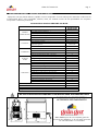
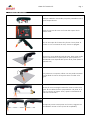
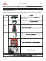
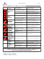
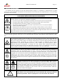
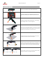
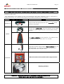
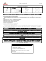
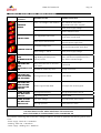
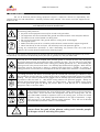
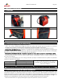
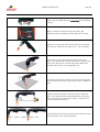
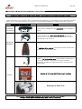
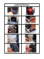
1
GALA CUT 350 K G.E.
E
GB
F
MANUAL TECNICO DE INSTRUCCIONES.
TECHNICAL INSTRUCTIONS MANUAL.
MANUEL TECHNIQUE D'INSTRUCTIONS.
Ref. 509.00.000 GALA CUT 350 K G.E. (230V - 50/60Hz)
E
ESTE EQUIPO DEBE SER UTILIZADO POR PROFESIONALES.
EN BENEFICIO DE SU TRABAJO LEA ATENTAMENTE ESTE MANUAL.
GB
THIS EQUIPMENT MUST BE USED BY PROFESSIONALS.
TO ASSIST YOUR WORK, CAREFULLY READ THIS MANUAL.
F
CET EQUIPEMENT DOIT ETRE UTILISE PAR DES PROFESSIONNELS DANS LE CADRE DE LEUR
TRAVAIL.LIRE ATTENTIVEMENT CE MANUEL.
Jaime Ferrán 19 50014 ZARAGOZA (Spain)
TLF.-34/976473410 FAX.-34/976472450
Ref.509.17.047 Ed.1
GALA CUT 350 K G.E.
E
INDICE DE TEMAS.
1. DESCRIPCION GENERAL.CARACTERISTICAS TECNICAS .................................Pag-3
2. TRANSPORTE E INSTALACION ......................................................................Pag-4
3. PUESTA EN MARCHA. FUNCIONAMIENTO Y REGLAJES.................................Pag-5
4. OPERACIONES DE MANTENIMIENTO. RECOMENDACIONES ........................Pag-8
5. ANOMALIAS. CAUSAS PROBABLES.SOLUCIONES POSIBLES ..........................Pag-10
6. MEDIDAS DE SEGURIDAD .............................................................................Pag-11
ANEXOS. .........................................................................................................Pag-31
- DECLARACION DE CONFORMIDAD MARCADO CE.
- PLANOS ELECTRICOS.
- PLANOS DE DESPIECE Y LISTAS DE REFERENCIAS.
GB
CONTENTS
CHAPTER 1. GENERAL DESCRIPTION. TECHNICAL CHARACTERISTICS ...............Page-12
CHAPTER 2. TRANSPORTATION AND INSTALLATION ........................................Page-13
CHAPTER 3. START-UP. OPERATION AND ADJUSTMENTS..................................Page-14
CHAPTER 4. MAINTENANCE OPERATIONS. RECOMMENDATIONS ....................Page-17
CHAPTER 5. ANOMALIES. PROBABLE CAUSES. POSSIBLE SOLUTIONS ...............Page-19
CHAPTER 6. SAFETY MEASURES.........................................................................Page-20
APPENDICES . ...................................................................................................Page-31
- EC MARKING STATEMENT OF CONFORMITY.
- ELECTRICAL DRAWINGS.
- PARTS EXPLOSION DRAWINGS AND REFERENCE LISTS.
F
TABLES DES MATIERES
CHAPITRE 1. DESCRIPTION GENERALE
CARACTERISTIQUES TECHNIQUES............................................... Pag-21
CHAPITRE 2. TRANSPORT ET INSTALLATION..................................................... Pag-22
CHAPITRE 3. MISE EN MARCHE. FONCTIONNEMENT ET REGLAGES................. Pag-23
CHAPITRE 4. OPERATIONS D'ENTRETIEN. RECOMMANDATIONS...................... Pag-26
CHAPITRE 5. ANOMALIES. CAUSES PROBABLES SOLUTIONS POSSIBLES........... Pag-28
CHAPITRE 6. MESURES DE SECURITE.................................................................Pag-29
ANNEXES. ........................................................................................................Pag-31
- DECLARATION DE CONFORMITE MARCHE CE
- PLANS ELECTRIQUES.
- PLANS DU DETAIL DES PIECES ET LISTES DE REFERENCES
DESPLEGADO DE ASA
METHOD TO RAISE THE HANLE
MÉTHODE POUR SOULEVER LA POIGNÉE
CLICK!
Pág. 2
GALA CUT 350 K G.E.
Pág. 3
1. DESCRIPCION GENERAL. CARACTERISTICAS TECNICAS.
Equipo de corte por plasma eléctrico soplado con aire comprimido. Corte de todo tipo de materiales conductores de
la electricidad: Acero, acero inoxidable, aluminio, latón, étc. Sistema inverter de alta portabilidad con compresor
incorporado. Utilización profesional
Características técnicas GALA CUT 350 K G.E.
GALA CUT 350 K
Ref. 509.00.000
CARACTERISTICAS TECNICAS
230 V ± 10%
Tensión alimentación (U1–1Ph 50/60 Hz)
ENTRADA
ALIMENTACION
Intensidad primaria máxima (I1max )
29 A
Intensidad primaria efectiva (I1eff)
17 A
Apto para Grupo Electrógeno.
SI
Protección contra tensión incorrecta. (hasta 450 V).
SI
Antorcha (Incluida en la máquina)
PT-40 (4 m)
Tipo de gas de entrada.
ANTORCHA
AIRE COMPRIMIDO
Neumático - por
cortocicuito
Sistema de ignición
Intensidad arco piloto
16 A
Caudal de trabajo
COMPRESOR
82 l/mín (3 bar)
Datos eléctricos
230 V/50 Hz/620 W
Nivel de ruido
68 dB
Sistema semiatomático de filtro y descarga.
SI
Espesor de acero máximo de corte (de separación)
SALIDA DE
CORTE
Margen de regulación de la corriente de corte I2
Intensidad máxima de corte
16 ÷ 35 A(130V)
35 A / 94 V (35%)
Intensidad nominal de corte (ED=100%)
21 A (100%)
Ignición “Back striking”. Máxima vida de consumibles
FUNCIONES
12 mm (15 mm)
SI
Modo de trabajo de reignición. (Corte de enrejados).
SI
Indicador tensión de red.
SI
Sangrado de aire.
SI
Protección por salto de témico de compresor.
SI
Protección por sobrecalentamiento.
SI
Protección por tensión U1 fuera de rango nominal.
SI
Protección por fallo en el electrodo.
SI
Protección portatoberas de antorcha.
SI
Indicación de Tensión secundaria.
SI
Grado de protección mecánica
IP 21
Dimensiones
260x 500x 447
Peso.
25Kg
Según normas EN60974-1, , EN60974-7 y , EN60974-10
NO UTILICE NUNCA ESTAS MAQUINAS DE SOLDADURA PARA DESCONGELAR TUBOS.
422
500
EMPLEE SOLO LOS REPUESTOS Y
ACCESORIOS RECOMENDADOS.
260
447
540
GALA GAR dispone de una completa gama de
accesorios de soldadura, en la que podrá encontrar
los más adecuados a su necesidad.
GALA CUT 350 K G.E.
Pág. 4
2. TRANSPORTE E INSTALACION.
2.1. TRANSPORTE
SEPARACION DEL SISTEMA DE TRANSPORTE
PORTA-ELECTRODOS DELANTERO Y TRASERO
2.2. INSTALACION ELECTRICA DE ALIMENTACION.
El emplazamiento deberá cumplir los siguientes requisitos:
- Lugar: Seco y ventilado. Alejado suficientemente del puesto de soldadura con el fin de evitar que el polvo y
la polución originada en el proceso de trabajo pueda introducirse en el equipo. No trabaje nunca bajo
lluvia.
- El cuadro de distribución en dónde se debe conectar la máquina, debe estar compuesto, al menos, de los
siguientes elementos:
INTERRUPTOR DIFERENCIAL (ID): Bipolar o Tripolar de una sensibilidad mínima de 300 mA. La misión de este
aparato es la de proteger a las personas de contactos directos o indirectos con partes eléctricas bajo
tensión. El interruptor diferencial se selecciona atendiendo a la Placa de características.
INTERRUPTOR AUTOMÁTICO (IA): Bipolar. Se recomienda un IA de 25 A.
¡IMPORTANTE! Compruebe que el cable está conectado a un enchufe con toma de tierra eficaz. La clavija debe
ser adecuada para un mínimo de 25 A. En caso de ser necesario el uso de una manguera de alimentación de más
longitud o la conexión a una alargadera, tenga en cuenta los valores de esta tabla.
Longitud
Hasta 15 m
>15 m Hasta 50 m
GALA CUT 350 GE
SECCIÓN
4 mm2
6 mm2
Estos valores son orientativos y se ven influidos
por el estado de los conductores, las conexiones y
la temperatura ambiente.
LAS INSTALACIONES ELECTRICAS SOLO DEBEN SER MANIPULADAS POR PERSONAL ESPECIALIZADO
2.3. INSTALACION ELECTRICA A GRUPO ELECTROGENO.
Los equipos GALA CUT 350 K G.E. son aptos para la instalación eléctrica a grupo electrógeno. Estos equipos
incorporan un sistema de protección que continuamente está verificando la tensión de alimentación, de tal forma
que en el momento que esta tensión quede fuera de los márgenes admitidos o esté distorsionada de forma
peligrosa, el equipo se protegerá aislando los circuitos sensibles de la red. En estas condiciones, el equipo
permanecerá apagado o se encenderá el indicador ámbar (véase MARCA 3, apartado 3). En el momento que la
tensión vuelva a ser adecuada el equipo estará listo para funcionar.
El funcionamiento correcto sobre grupo electrógeno requiere una potencia recomendada de:
Grupo monofásico Pmín=10 KVA
GALA CUT 350 K G.E.
Pág. 5
3. PUESTA EN MARCHA. FUNCIONAMIENTO Y REGLAJES.
3.1 MANDOS DE OPERACION.
Una vez realizada la instalación eléctrica de alimentación puede proceder a la puesta en marcha del equipo. En
este apartado se describe el sistema de mando y regulación.
Panel de control del equipo GALA CUT 350K G.E.
1
3
4
5
6
2
Panel trasero.
7
Panel frontal
8
Antorcha
Marca
Símbolo
Descripción de uso.
1
ON
Interruptor de puesta (en frente posterior) en marcha e indicador.
2
(A)
Regulación de corriente de salida en Amperios.
3
Indicador de actuación de la protección térmica.
4
Indicador de presencia de tensión en la antorcha e interruptor antorcha.
5
Indicador de desconexión térmica del compresor.
6
Indicador de la existencia de un problema con los accesorios (Véase apartado 5)
7
Purga de aire.
8
Pulsador de accionamiento de arco de corte por plasma
GALA CUT 350 K G.E.
Pág. 6
3.2 SECUENCIA DE OPERACIONES PARA LA PUESTA EN MARCHA DEL EQUIPO
1.
2.
3.
4.
5.
Seleccione y coloque el tipo de accesorios en función del trabajo a realizar (Véase apartado 3.3).
Conectar la clavija de alimentación a la red eléctrica.
Coloque la masa a la pieza a cortar.
Conectar el equipo y regular la corriente de soldadura deseada mediante el potenciómetro "2" Figura 2.
Puede comenzar la operación de corte (Véase apartado 3.4).
3.3 SELECCION Y COLOCACION DE ACCESORIOS.
Ø Tobera corta diám. 0.9 (40 A)
Ø Tobera larga 0.9 (40 A)
HASTA 15 mm
Esquinas y accesos difíciles
DESGASTE
BAJO
BAJO
VELOCIDAD DE CORTE
ALTA
NORMAL
SEPARACION A LA PIEZA
CONTACTO
CONTACTO
ESPESOR Y FORMA DE PIEZA
MAXIMAS VELOCIDADES Y ESPESORES DE CORTE.
ESPESOR – VELOCIDAD DE CORTE
2.5 m/min
1.0 m/min
0,20 m/min
ACERO
ALUMINIO
INOXIDABLE
12 mm
10 mm
8 mm
m/mín
5 mm
5 mm
2.5 mm
2.5 mm
3 mm
1 mm
GALA CUT 350 K G.E.
Pág. 7
3.4 OPERACION DE CORTE.
Verifique estado de consumibles, limpie la portatobera con el
cepillo limpia-toberas.
1
3
4
5
6
2
Regule la corriente de corte en función del espesor de la
pieza a cortar.
7
Pulse el interruptor de la antorcha y forme el arco piloto. Si
durante 3 s no se comienza el corte, el arco se apagará.
Comience el corte desde el borde la pieza. Para cortar puede
apoyar la antorcha en la pieza pero no ejerza presión. La
velocidad de corte depende del espesor de la pieza (Véase el
apartado 3.3)
Si la pieza tiene un espesor inferior a 5 mm puede comenzar
el corte desde el interior de la pieza como se indica en la
figura.
Durante el corte mantenga la antorcha como se indica en la
figura. El arco debe formarse perpendicular a la pieza. Si el
arco se inclina o no llega a cortar, quizá la velocidad de la
antorcha sea elevada.
La máquina permite cortar piezas con huecos o agujeros sin
necesidad de reiniciar el arco (Corte de enrejillados)
GALA CUT 350 K G.E.
Pág. 8
4. OPERACIONES DE MANTENIMIENTO. RECOMENDACIONES.
UN BUEN MANTENIMIENTO DEL EQUIPO EVITARA UN GRAN PORCENTAJE DE AVERIAS.
Antes de realizar cualquier operación sobre la máquina coloque el interruptor principal en la posición "O" y
desconecte la máquina de la red.
La intervención sobre la máquina para la realización de operaciones de mantenimiento y reparación, debe
realizarse por personal especializado. Las frecuencias recomendadas presuponen un uso frecuente de la máquina.
FRECUENCIA DE COMPROBACIÓN
CADA USO
ACCIÓN
Verifique el estado y la idoneidad de los accesorios para el
trabajo a realizar. Proceda a limpieza de tobera mediante
cepillo limpiatoberas.
La antorcha dispone de un interruptor de seguridad. Verifique
que con el porta tobera quitado jamás se enciende el indicador
6, tras pulsar la antorcha.
SEMANAL
Las ventilaciones de la máquina deben mantenerse libres. Esta
debe ubicarse en un emplazamiento donde exista renovación
de aire.
Verifique que los aislamientos de mangueras de alimentación y
antorchas no han sufrido desperfectos. El proceso de corte
desprende materiales a altas temperaturas que pueden
dañarlos.
3 MESES
Sople con aire comprimido el interior de la máquina
Limpieza de filtros de aire
F
¡ATENCIÓN!: SEPARE SUFICIENTEMENTE LA MAQUINA DEL PUESTO DE TRABAJO.
EVITE LA ENTRADA DE POLVO METÁLICO AL EQUIPO.
GALA CUT 350 K G.E.
Pág. 9
CAMBIO DE LOS CONSUMIBLES
4.2 RECOMENDACIONES PARA REDUCIR LAS MOLESTIAS POR COMPATIBILIDAD ELECTROMAGNETICA (CEM).
El usuario es responsable de la instalación y utilización del material de soldadura siguiendo las instrucciones de
este manual y las siguientes recomendaciones:
Antes de instalar el material de soldadura debe tener en cuenta la presencia en los alrededores de:
•
•
•
•
•
•
Cables de potencia, control, señalización y teléfono.
Receptores y transmisores de radio y televisión.
Ordenadores y otros equipos de control.
Equipo crítico de seguridad.
Personas con estimuladores cardíacos o aparatos para la sordera.
Material de medida y calibración.
Para reducir las molestias por CEM tenga en cuenta la hora del día en que la soldadura u otras actividades se
llevarán a cabo. Aleje las posibles víctimas de interferencias de la instalación de soldadura.
El aparato, siguiendo la clasificación EMC de equipos según la CISPR 11, atiende al grupo 1 clase A.
CONECTE SIEMPRE LA MÁQUINA A LA ALIMENTACIÓN CON UNA TOMA DE TIERRA EFICAZ.
EN CASO DE PRECISAR BLINDAJES O FILTRADO DE RED SUPLEMENTARIO CONSULTE CON NUESTRO SERVICIO
TÉCNICO.
REALICE LAS OPERACIONES DE MANTENIMIENTO DEL EQUIPO DESCRITAS EN ESTE MANUAL.
UTILICE CABLES DE SOLDADURA TAN CORTOS COMO SEA POSIBLE Y COLOCADOS UNO JUNTO A OTRO
CERCA DEL SUELO.
EN CASO DE PUESTA A TIERRA DE LA PIEZA A SOLDAR TENGA EN CUENTA LA SEGURIDAD DEL OPERARIO Y LAS
REGLAMENTACIONES NACIONALES.
EQUIPO PREVISTO PARA USARSE EN ENTORNO INDUSTRIAL, PUDIENDO EXISTIR DIFICULTADES AL ASEGURAR LA
COMPATIBILIDAD ELECTROMAGNÉTICA EN OTROS AMBIENTES CAUSADOS POR PERTURBACIONES
CONDUCIDAS Y RADIADAS.
FORMULACION PARA PIEZAS DE REPUESTO:
Indique:
1º Maquina, Referencia y Nº de serie.
2º Tensión de Alimentación/Frecuencia.
3º Nº de piezas, descripción y referencia.
EJEMPLO:
GALA CUT 350 K G.E., Ref. 509.00.000, Nº serie: 07070451
(230-50/60Hz)
1Ud APRIETE CABLE; Ref. 492.16.014
GALA CUT 350 K G.E.
Pág. 10
5. ANOMALIAS. CAUSAS PROBABLES. SOLUCIONES POSIBLES.
SÍNTOMA.
ANOMALÍA
NO FUNCIONA
NADA.
SALTA
LIMITADOR.
CAUSA PROBABLE.
SOLUCIÓN POSIBLE.
La máquina carece de tensión.
Cambiar la toma y/o manguera de
alimentación. Observar si hay algún
magnetotérmico "saltado".
Tensión de red > 380 V.
Compruebe tensión de alimentación.
Interruptor ON/OFF averiado.
Reemplazar interruptor ON/OFF.
Interruptor magneto-térmico bajo.
Cámbielo por otro de mayor calibre.
Corte a niveles de corriente menores.
Puede existir un cortocircuito.
Separe la máquina de la red y verifique
manguera de alimentación.
Equipo sobrecalentado.
LED TÉRMICO
ILUMINADO
Espere a que el equipo se enfríe.
Tensión de red > 265 V.
Compruebe tensión de alimentación.
Salto térmico del compresor. Falta
de presión
Espere a que se refrigere el compresor, el
sistema será operativo una vez que se
apague la indicación luminosa
Electrodo mal colocado o no
colocado
Colocar el electrodo
Electrodo o tobera muy
desgastados
Cambiar accesorios
NO HAY ARCO
PILOTO Y LED
ACCESORIOS
INTERMITENTE
Olvidó el difusor de aire
Colocar el difusor
NO HAY ARCO
PILOTO Y NO SE
ENCIENDE EL LED
TENSION DE
CORTE
Portatobera mal colocado
Colocar correctamente el portatoberas
HAY ARCO
PILOTO PERO NO
CORTA
Olvidó la Masa
Colocar la masa a la pieza a cortar
Velocidad de corte elevada
Reduzca la velocidad
HAY ARCO
PILOTO PERO SE
APAGA
Tensión de red baja
Verifique la alimentación del equipo
Presión muy elevada
Baje la presión en la antorcha
NO HAY ARCO
PILOTO Y LED DE
COMPRESOR
ENCEDIDO
NO HAY ARCO
PILOTO Y LED
ACCESORIOS
ENCENDIDO
TANTO AL COMIENZO COMO AL FINAL DE UNA REPARACION COMPRUEBE LOS NIVELES DE AISLAMIENTO
DEL EQUIPO. DESCONECTE LAS PLACAS ELECTRÓNICAS AL MEDIR EL AISLAMIENTO.
SOPLE CON AIRE COMPRIMIDO EL INTERIOR DEL EQUIPO.
El medidor de aislamiento será de una tensión de 500 V D.C y será aplicado en los siguientes puntos del circuito:
- Alimentación - Tierra: Ra > 50 Mohms.
- Soldadura - Tierra: Ra > 50 Mohms.
- Alimentación - Soldadura: Ra > 50Mohms.
GALA CUT 350 K G.E.
Pág. 11
6. MEDIDAS DE SEGURIDAD.
La utilización de los equipos de corte por plasma eléctrico exige en su utilización y mantenimiento un grado
máximo de responsabilidad. Aconsejamos leer atentamente este manual, de ello dependerá que el uso que haga
del equipo sea el correcto.
En beneficio de su seguridad y la de los demás recuerde que:
¡ CUALQUIER PRECAUCION PUEDE SER INSUFICIENTE
Los equipos de corte a los que se refiere este manual son de carácter eléctrico, es importante, por
lo tanto, observar las siguientes medidas de seguridad:
•
•
•
•
•
•
•
La intervención sobre el equipo debe realizarla exclusivamente personal especializado.
El equipo debe quedar conectado a la toma de tierra siendo esta siempre eficaz.
El emplazamiento del equipo no debe ser una zona húmeda.
No utilizar el equipo si los cables de masa o antorcha de corte se encuentran dañados.
Utilizar recambios originales.
Asegúrese de que la pieza a cortar hace un perfecto contacto eléctrico con la masa W.
Evitar apoyarse directamente sobre la pieza de trabajo. Utilizar guantes de protección.
En cualquier intervención de mantenimiento o desmontaje de algún elemento interior de la máquina
debe desconectarse esta de la alimentación eléctrica
La manipulación sobre las antorchas de corte por plasma se realizara con el equipo desconectado (Posición OFF
(O) del interruptor general). Evitar tocar con la mano desnuda las partes eléctricamente activas (antorcha, masa,
etc.).
Es conveniente limpiar la pieza de trabajo de la posible existencia de grasas y disolventes dado que
estas pueden descomponerse en el proceso de corte desprendiendo un humo que puede ser muy
tóxico. Esto mismo puede suceder con aquellos materiales que incorporen algún tipo de tratamiento
superficial (cincado, galvanizado etc.). Evítese en todo momento la inhalación de los humos
desprendidos en el proceso. Protéjase del humo y polvo metálico que pueda originarse. Utilice
máscaras anti-humo homologadas . El trabajo con estos equipos debe realizarse en locales o
puestos de trabajo donde exista una adecuada renovación de aire. La realización de procesos de
corte en lugares cerrados aconseja la utilización de aspiradores de humo adecuados.
En el proceso de corte el arco eléctrico formado emite unas radiaciones de tipo infrarrojo y
ultravioleta, estas son perjudiciales para los ojos y para la piel, por lo tanto debe proteger
convenientemente estas zonas descubiertas con guantes y prendas adecuadas. La vista debe quedar
protegida con un sistema de protección homologado de un índice de protección mínimo de 11. Con
máquinas de corte eléctrico utilice gafas de protección. Utilice siempre elementos de protección
homologados. Nunca utilizar lentes de contacto, pueden quedar adheridas a la cornea a causa del
fuerte calor emanado en el proceso. Tenga en cuenta que el arco se considera peligroso en un radio
de 15 metros.
Durante el proceso de corte saltan proyecciones de material fundido, deben tomarse
las debidas precauciones. En las proximidades del puesto de trabajo debe existir un
extintor. Evitar la existencia de materiales inflamables o explosivos en las proximidades
del puesto de trabajo. Evitar que se produzca fuego a causa de las chispas o escorias.
Utilice calzado homologado para este tipo de operaciones. En los procesos de corte por
plasma eléctrico se produce un alto nivel de ruido. Se recomienda utilizar medios de
protección auditiva homologados.
No dirigir nunca el trazado de la una antorcha de corte por plasma
hacia las personas. Existe el peligro de una activación del sistema.
GALA CUT 350 K G.E.
Pág. 12
1. GENERAL DESCRIPTION. TECHNICAL CHARACTERISTICS.
The cutting function of the GALA CUT 350 K machines is carried out by electric plasma blown with compressed
air. They can cut all kinds of electricity conductor material: Steel, stainless steel, aluminium, brass, etc. Plasma
with built compressor. Using professional. Inverter high portability.
Technical characteristics GALA CUT 350 K G.E.
Technical characteristics
GALA CUT 350 K
Ref. 509.00.000
Supply voltage (U1 - 1Ph. 50/60 Hz)
Maximum primary intensity (I1max )
POWER INPUT Effective primary intensity (I1eff)
Protection against connection at 400V
Suitable for generating set.
Torch (Included in the machine)
230 V ± 10%
29 A
17 A
SI
SI
TORCH
Type of gas input
PT-40 (4 m)
Compressed air
Back striking
(Without HF)
Ignition system
Pilot arc intensity
Work Flow
Electrical data
COMPRESSOR
Noise level
Semiautomatic System Filter and unloading.
Maximum thickness steel cutting (separation).
Cutting current adjustment margin I2
CUT OUPUT
Maximum cutting intensity
Rated cutting intensity (ED=100%)
Re-ignition mode. (Cutting framework).
Air-bleed.
Overheating protection.
FUNCTIONS
Secondary voltage indication
Thermal Protection compressor
Protection against fault in electrode.
Torch nozzle-support protection.
IP mechanical protection degree
Dimensions WIDTH x HEIGHT x LENGTH (mm)
Weight (Kg.).
According norms; EN60974-1, , EN60974-7 y , EN60974-10
16 A
82 l/mín (3 bar)
230 V/50 Hz/620 W
68 dB
YES
12 mm (15 mm)
16 ÷ 35 A(130V)
35 A / 94 V (35%)
21 A (100%)
YES
YES
YES
YES
YES
YES
YES
IP 21
260x 500x 447
25Kg
NEVER USE THESE WELDING MACHINES TO DEFROST PIPES.
422
500
ONLY USE RECOMMENDED SPARE
PARTS AND ACCESSORIES.
260
447
540
GALA GAR has a complete range of welding
accessories, where you will find everything you
need.
GALA CUT 350 K G.E.
Pág. 13
2. TRANSPORTATION AND INSTALLATION.
2.1. TRANSPORTATION
SEPARATION OF THE TRANSPORT SYSTEM
STOCK CONSUMABLES FRONT AND REAR.
2.2. ELECTRICAL INSTALLATION.
The location shall comply with the following requisites:
- Place: dry and ventilated. Far enough away from the welding position in order to prevent dust and
contaminants, caused by the work process, entering the equipment. Never work in the rain.
- The distribution panel where the machine should be connected, must have the following elements, at least:
DIFFERENTIAL CIRCUIT BREAKER (ID): Bi-polar or Tri-polar with a minimum sensitivity of 300 mA. The mission
of this device is to protect people from direct or indirect contact with electrical parts under power. The differential
circuit breaker is selected in accordance with the characteristics plate.
AUTOMATIC CIRCUIT BREAKER (IA):
characteristics plate (25 A recommended).
Bi-polar.
The device shall be selected in accordance with the
IMPORTANT! Verify that the wire is connected to a plug with an efficient ground.
Any supply voltage that is outside the nominal margin gives rise to the activation of the protection system,
preventing the welding operation.
LENGTH
Up to 15 m
>15 m Up to 50 m
GALA 2000 G.E.
CROSS-SECTION
4 mm2
6 mm2
If it is necessary to use a longer power supply
cord or a connection to an extension cord, keep
in mind the values in the following table.
ELECTRICAL INSTALLATIONS SHOULD ONLY BE HANDLED BY SPECIALISED PERSONNEL.
BEFORE STARTING THE EQUIPMENT, VERIFY THAT THE ELECTRODE TONG IS SEPARATED
FROM THE WELDING MASS.
2.3. ELECTRICAL INSTALLATION TO ELECTRICAL GENERATOR SET.
The GALA CUT 350 K G.E. appliances are suitable for electrical installation to electrical generator set. These
appliances include a protection system, which continuously verifies the supply voltage, in such a way that
whenever this voltage is outside the admitted margins or is dangerously distorted, the appliance will protect itself,
by insulating the sensitive circuits of the network. Under these conditions, the appliance will remain switched off
or the amber coloured indicator, “3”, will light up (see section 3). When the voltage is suitable again, the
appliance will be ready to operate.
For correct operation with electrical generator set the following minimum powers are required:
Single-phase set, Min.p = 10 KVA
GALA CUT 350 K G.E.
Pág. 14
3. START-UP. OPERATION AND ADJUSTMENTS.
3.1 OPERATION CONTROLS.
Once the electrical power supply installation has been carried out, you can proceed to start the equipment up.
This section describes the control and regulation system.
Control panel of the GALA CUT 350 G.E. equipment
1
3
4
5
6
2
Rear panel.
7
Front panel
8
Torch
Mark
Symbol
Description of use.
1
ON
On switch and indicator.
2
(A)
Outlet current regulation in Amperes.
3
Thermal protection application indicator.
4
Indicator of voltage presence in torch and torch switch.
5
6
Indicator of existence of a problem with accessories (See section 5)
7
Air-bleed.
8
Torch swich
GALA CUT 350 K G.E.
Pág. 15
3.2 OPERATION SEQUENCE TO START UP THE EQUIPMENT
1.
2.
3.
4.
5.
Select and fit the type of accessories depending on the work to carry out. (See section 3.3).
Connection power supply plug to the mains.
Connect ground to the part to be cut
Connect the equipment and regulate the desired welding current with potentiometer "2” Figure 2.
You can now begin the cutting operation. (See section 3.4).
3.3 SELECTING AND FITTING ACCESSORIES.
Nozzle Ø = 0.9 (40 A)
Long Nozzle Ø = 0.9 (40 A)
UP TO 15 mm
Corners and difficult accesses
WEAR
LOW
LOW
CUTTING SPEED
HIGH
NORMAL
CONTACT
CONTACT
PART THICKNESS AND SHAPE
SEPARATION TO PART
THICK- CUT SPEED
2.5 m/min
1.0 m/min
0,20 m/min
STEEL
ALUMINIUM
STAINLESS
12 mm
10 mm
8 mm
m/mín
5 mm
5 mm
2.5 mm
2.5 mm
3 mm
1 mm
GALA CUT 350 K G.E.
Pág. 16
3.4 CUTTING OPERATION
Check the consumables. Clean nozzle with the brush.
1
3
4
5
6
2
Regulate the welding current depending on the type of cut,
the accessories fitted and the material and thickness to be
cut.
7
Press the torch switch and form the pilot arc. If the cutting
does not begin within 3 s. the arc will go out.
Start the cut from the edge of the part. To cut you can rest the
torch on the part but do not exert pressure. The cutting speed
depends on the part thickness. (See section 3.3)
If the part is less than 5 mm thick the cutting can start from
the interior of the part as shown in the figure.
During the cutting operation hold the torch as indicated in the
figure. The arc must be formed perpendicular to the part. If
the arc slopes or does not cut, the torch speed may be high.
Parts with gaps or holes can be cut with the machine without
having to re-start the arc (Cutting framework)
GALA CUT 350 K G.E.
Pág. 17
4. MAINTENANCE OPERATIONS. RECOMMENDATIONS.
GOOD MAINTENANCE OF THE EQUIPMENT WILL PREVENT A LARGE PERCENTAGE OF FAULTS.
Before carrying out any operations on the machine place the general switch to “0” position and disconnect the
machine from the mains
Any interventions to the machine to carry out maintenance and repair operations must be performed by
authorised personnel. The recommended frequencies presuppose frequent use of the machine.
VERIFICATION FREQUENCY
IN EACH USE
ACTION
Verify the state and appropriateness of the accessories for the
work to be carried out.
The torch has a safety switch. Verify that indicator 6 never lights
up when the nozzle-support has been removed, after pressing
the torch.
WEEKLY
The machine ventilations must be kept free. The machine must
be placed in a location where there is air renewal.
Verify that the power supply and torch hose insulations have not
suffered damage. The cutting process gives off materials at
high temperatures that may harm them.
3 MONTHS
Blow the inside of the machine with compressed air
Cleaning air filters
F
WARNING! SUFFICIENTLY SEPARATE THE MACHINE FROM THE WORKSTATION.
PREVENT METAL DUST ENTERING THE EQUIPMENT.
GALA CUT 350 K G.E.
Pág. 18
CHANGE OF CONSUMABLES
4.2 RECOMMENDATIONS FOR REDUCING ELECTROMAGNETIC COMPATIBILITY (CEM) PROBLEMS.
The user is responsible for the installation and use of the welding material according to the instructions in this
manual and the following recommendations.
Before installing the welding material, the presence of the following in the surrounding area must be kept in
mind:
• Wiring for power, control, signalling, and telephones.
• Radio and television receivers and transmitters.
• Computers and other control equipment.
• Critical security equipment.
• Persons with pace makers or hearing aids.
• Measurement and calibration equipment.
In order to reduce CEM problems, keep in mind the time of day when welding or other activities will be carried
out. Move possible interference victims away from the welding installation. This equipment, according to
CISPR11, concerns group 1 class A.
ALWAYS CONNECT THE MACHINE TO POWER USING AN EFFICIENT GROUND.
IN CASE PROTECTIVE DEVICES OR SUPPLEMENTARY ELECTRICAL SYSTEM FILTERS ARE NEEDED, CONSULT
OUR TECHNICAL SERVICE.
PERFORM THE MAINTENANCE OPERATIONS DESCRIBED IN THIS MANUAL.
USE THE SHORTEST WELDING WIRES POSSIBLE AND KEEP THEM PLACED NEXT TO EACH OTHER NEAR THE
FLOOR.
IN CASE THE WELDING PIECE IS GROUNDED, KEEP IN MIND OPERATOR SAFETY AND NATIONAL
REGULATIONS.
EQUIPMENT DESIGNED FOR USE IN INDUSTRIAL ENVIRONMENT, WHICH MAY POSE DIFFICULTIES WHEN
GUARANTEEING ELECTROMAGNETIC COMPATIBILITY IN OTHER ENVIRONMENTS DUE TO CONDUCTED
AND RADIATED DISTURBANCES.
FORMULA FOR MAKING ORDERS FOR SPARE PARTS:
Indicate:
1 - Machine, Reference and Serial no.
2 - Supply Voltage / Frequency.
3 - No. of parts, description and reference of it.
EXAMPLE:
GALA CUT 350 K G.E., Ref. 509.00.000, Serial no. 07070451
(230-50/60Hz)
1Unit APRIETE CABLE; Ref. 492.16.014
GALA CUT 350 K G.E.
Pág. 19
5. ANOMALIES. PROBABLE CAUSES, POSSIBLE SOLUTIONS.
SYMPTOM.
ANOMALY
NOTHING
WORKS.
PROBABLE CAUSE.
POSSIBLE SOLUTION.
Change the intake and/or power supply
There is no voltage in the machine. hose. Observe if any of the
magnetothermals have “tripped".
Mains voltage > 380 V.
Check power supply voltage
Faulty ON/OFF switch.
Replace ON/OFF switch.
Low magnetothermal switch.
Change for another with a larger calibre.
Cut at lower current levels.
There may be a short-circuit.
Disconnect the machine from the mains
and verify power supply hose.
LIMITER TRIPS.
Overheated equipment
Wait until the equipment cools down
THERMAL LED ON
Mains voltage > 265 V.
NO PILOT ARC
High Heating Of Compressor.
AND
COMPRESSOR LED Lack of pressure
ON
Check power supply voltage.
Wait to refrigerate the compressor, the
system will become operational once it
goes off the indication bright
Badly fitted electrode or none has
been fitted.
Fit electrode
Electrode or nozzle very worn
Change accessories
NO PILOT ARC
AND ACCESSORY
LED FLASHING
You forgot the air diffuser
Fit the diffuser
NO PILOT ARC
AND CUTTING
VOLTAGE LED
NOT ON
Nozzle-support badly fitted.
Correctly fit the nozzle-support
THERE IS PILOT
ARC BUT DOES
NOT CUT
You forgot the Ground
Place ground on part to be cut
High cutting speed
Reduce speed
THERE IS PILOT
ARC BUT DOES
NOT GO OFF
Low mains voltage
Verify equipment power supply
Very high pressure
Lower pressure in torch
NO PILOT ARC
AND
ACCESSORIES LED
ON
BOTH AT THE START AND END OF A REPAIR, CHECK THE EQUIPMENT INSULATION LEVELS. DISCONNECT
THE ELECTRONIC PLATES WHEN MEASURING THE INSULATION
BLOW THE INSIDE OF THE EQUIPMENT WITH COMPRESSED AIR.
The insulation measuring device will have a voltage of 500 Vcc and will be applied at the following points of the
circuit:
- Power supply - Earth: Ra > 50 Mohms.
- Welding - Earth: Ra > 50 Mohms.
- Power supply - Welding: Ra > 50Mohms.
GALA CUT 350 K G.E.
Pág. 20
6. SAFETY MEASURES
The use of electrical plasma cutting equipment requires a maximum amount of responsibility with
respect to their use and maintenance. Carefully read this safety manual. The correct use of the equipment will
depend on this.
In benefit of your safety and that of others, remember that:
ANY PRECAUTION MAY BE INSUFFICIENT!
The cutting equipment referred to in this manual are electrical. It is important therefore to observe
the following safety measures.
•
•
•
•
•
•
•
Any work on the equipment must only be carried out by specialists.
The equipment must be connected to the ground connection and this must always be effective.
The machine must not be located in a damp place.
Do not use the equipment if the ground cables or cutting torch are damaged.
Use original spares.
Make sure that the part to be cut makes perfect electrical contact with the equipment ground.
Never lean directly on the work part. We will always work with protection gloves.
During any maintenance operations or when dismantling any element from the inside of the
machine, this must be disconnected from the electricity supply.
Any work on the plasma cutting torches will be done with the equipment disconnected (OFF Position (0) on the
on/off switch). Do not touch the electrically active parts (torch, ground, etc.) with your bare hand.
The part to be cut should be cleaned from possible grease or solvents as these may decompose
during the cutting process giving off fumes which could be very toxic. This can also occur with those
materials which have some kind of surface coating (zinc-plated, galvanised, etc.). Avoid inhaling the
fumes given off in the process at all times. Use officially approved anti-fume goggles. Work with this
equipment must be carried out in places or working posts where there is suitable air renewal. If
cutting processes are carried out in closed places the use of suitable fume extractors is recommended.
In cutting processes, the electric arc formed gives off infrared and ultraviolet type radiations: these
are harmful for the eyes and skin, so these areas must be suitably protected with gloves and suitable
clothing. The eyes must be protected with goggles with an officially approved protection system with
a protection index of at least 11. With electric cutting machine use protection goggles. Always use
officially approved protection elements. Never use contact lenses. They may adhere to the cornea
due to the great heat given off during the process. Bear in mind that the arc is considered to
dangerous within a 15 metre radius.
Cast material projections are given off during the cutting process so due precautions
must be taken. There must be a fire-extinguisher near to the working area. Do not
keep inflammable material or explosives near to the working post. Prevent fire caused
by sparks or slag. Use officially approved footwear for this type of operations. A high
noise level occurs in the electric plasma cutting processes. Thus, the use of officially
approved auditive protection means is recommended.
Never direct the path of the plasma cutting torch towards people.
The danger exists of activating the system.
GALA CUT 350 K G.E.
Pág. 21
1. DESCRIPTION GÉNÉRALE. CARACTÉRISTIQUES TECHNIQUES.
Les machines GALA CUT 350 K remplissent la fonction de coupe au plasma électrique à air comprimé. Elles
peuvent couper toute sorte de matériaux conducteurs d'électricité : Acier, acier inoxydable, aluminium, laiton, etc.
Plasma avec compresseur. Utilisation professionnelle. Inverter haute portabilité.
Caractéristiques techniques GALA CUT 350 K G.E.
GALA CUT 350 K
Ref. 509.00.000
Caractéristiques techniques.
POWER
INPUT
TORCHE
Tension d’alimentation (U1 - 1Ph. 50/60 Hz)
Intensité primaire maximum (I1max )
Intensité primaire effective (I1eff)
Protection contre branchement à 400 V
Apte pour groupe électrogène.
Torche (inclus dans la machine)
Gaz
230 V ± 10%
29 A
17 A
QUI
QUI
PT-40 (4 m)
L'air comprime
Back striking
(Sans HF)
Forme d’ignition
Intensité de l'arc pilote
Débit d’air
Compresseur Caractéristiques électriques
Niveau sonore
Filtre Pneu.
Épaisseur maximale de coupe (séparation).
Marge de réglage du courant de coupe I2
COUPE
Intensité maximum de coupe
Intensité nominale de coupe (ED=100%)
Mode de travail de rallumage (Coupe de grilles)
Purge d’air
Protection contre la surchauffe
FONCTIONS
Indication de tension secondaire
Protection contre la surchauffe du compresseur
Protection contre la défaillance de l’électrode
Protection du porte-bec de torche
Degré de protection mécanique IP
Dimensions LARGEUR X HAUTEUR X LONGUEUR (mm)
Poids sans systeme de transport (Kg)
Selon les normes; EN60974-1, , EN60974-7 y , EN60974-10
16 A
82 l/mín (3 bar)
230 V/50 Hz/620 W
68 dB
QUI
12 mm (15 mm)
16 ÷ 35 A(130V)
35 A / 94 V (35%)
21 A (100%)
QUI
QUI
QUI
QUI
QUI
QUI
QUI
IP 21
260x 500x 447
25Kg
NE JAMAIS UTILISER CES ÉQUIPEMENTS DE SOUDURE POUR DÉGIVRER DES TUYAUX.
422
500
N’UTILISEZ QUE LES PIÈCES DE
RECHANGE ET LES ACCESSOIRES
RECOMMANDÉS.
260
447
540
GALA GAR dispose d’une gamme complète
d’accessoires de soudure adaptés à chacun de vos
besoins
GALA CUT 350 K G.E.
Pág. 22
2. TRANSPORT ET INSTALLATION.
2.1. TRANSPORT
SÉPARATION DU SYSTÈME DE TRANSPORT
STOCK CONSOMMABLES AVANT ET ARRIÈRE.
MANIPULEZ L’ÉQUIPEMENT AVEC SOIN POUR QU’IL DURE PLUS LONGTEMPS !
2.2. INSTALLATION ÉLECTRIQUE D’ALIMENTATION.
L’emplacement devra satisfaire les conditions suivantes :
- Lieu : sec et aéré. Suffisamment éloigné du poste de soudure afin d’éviter que la poussière et la pollution
provoquée par le travail ne pénètrent dans l’équipement. Ne jamais travailler sous la pluie.
- Le tableau de distribution où la machine sera branchée doit être composé au moins des éléments suivants :
INTERRUPTEUR DIFFÉRENTIEL (ID) : Bipolaire ou tripolaire d’une sensibilité minimum de 300 mA. Cet appareil sert
à protéger les personnes des contacts directs ou indirects avec les parties électriques de basse tension. L’interrupteur
différentiel est sélectionné en fonction de la plaque de caractéristiques.
INTERRUPTEUR AUTOMATIQUE (IA) : Bipolaire. L’appareil sera choisi selon la plaque de caractéristiques. (25 A)
Le branchement au secteur se fera au moyen du câble d’entrée. ATTENTION ! Vérifiez si le câble est branché à une
prise avec terre efficace.
Toute tension d’alimentation hors de la marge nominale provoque le déclenchement du système de protection
empêchant l’opération de soudure.
Longueur
10 m
15 m-50 m
GALA CUT 350 K GE
SECTION
4 mm2
6 mm2
S’il faut un câble d’alimentation plus long est
nécessaire ou une rallonge, tenir compte des
valeurs de ce tableau.
LES INSTALLATIONS ÉLECTRIQUES NE DOIVENT ÊTRE MANIPULÉES QUE PAR UN PERSONNEL SPÉCIALISÉ.
2.3. INSTALLATION ÉLECTRIQUE AU GROUPE ÉLECTROGÈNE.
Les équipements GALA CUT 350 K GE sont aptes pour l’installation électrique à un groupe électrogène. Ces
équipements intègrent un système de protection qui vérifie en continu la tension d’alimentation de manière à ce que
lorsque cette tension se trouve en dehors des marges admises ou devient dangereuse, l’équipement se protègera en
isolant les circuits sensibles du secteur. Dans ces conditions, l’équipement restera éteint ou l’indicateur orange « 3 »
s’allumera (voir paragraphe 3). Dès que la tension sera corrigée, l’équipement pourra fonctionner.
Le bon fonctionnement sur le groupe électrogène requiert les puissances minimums suivantes :
GALA CUT 350 K G.E.
Pág. 23
Groupe monophasé Pmin=10KVA
3. MISE EN MARCHE. FONCTIONNEMENT ET RÉGLAGES.
3.1 COMMANDES D’OPÉRATION.
Une fois l’installation électrique de l’alimentation réalisée, il faut procéder à la mise en marche de l’équipement.
Le système de commande et de réglage est décrit ci-après.
Panneau de contrôle de l’équipement GALA CUT 350 K G.E.
1
3
4
5
6
2
Panneau arrière.
7
8
Panneau frontal
Torche
Marque
Symbole
Description d’utilisation.
1
ON
Interrupteur de mise en marche et indicateur.
2
(A)
Réglage du courant de sortie en ampères.
3
Indicateur de fonctionnement de la protection thermique.
4
Indicateur de présence de tension dans la torche et interrupteur de la torche.
5
Absence de pression ou pression basse (3 bars).
6
Indicateur de l’existence d’un problème avec les accessoires (Voir chapitre 5)
7
Purge d’air.
8
Interrupteur de la torche.
GALA CUT 350 K G.E.
Pág. 24
3.2 SÉQUNCE D’OPÉRATIONS POUR LA MISE EN MARCHE DE L’ÉQUIPEMENT.
1.
2.
3.
4.
5.
Choisir et poser le type d’accessoires en fonction du travail à réaliser. (voir paragraphe 3.3)
Brancher la prise d’alimentation au réseau électrique.
Brancher la masse à la pièce à couper.
Brancher l’équipement et régler le courant de soudure voulu au moyen du potentiomètre "4" Figure 2.
Commencer l’opération de coupe (Voir paragraphe 3.4).
3.3 CHOIX ET POSE DES ACCESSOIRES.
ÉPAISSEUR ET FORME DE PIÈCES
USURE
VITESSE DE COUPE
SÉPARATION DE LA PIÈCE
Ø bec = 0.9 (40A)
Long Nozzle Ø = 0.9 (40 A)
JUSQU’À 15 mm
Angles et accès difficiles
LOW
FAIBLE
HAUTE
NORMALE
CONTACT
CONTACT
ÉPAISSEUR - VITESSE DE COUPE
2.5 m/min
1.0 m/min
0,20 m/min
ACIER
ALUMINIUM
INOXYDABLE
12 mm
10 mm
8 mm
m/mín
5 mm
5 mm
2.5 mm
2.5 mm
3 mm
1 mm
GALA CUT 350 K G.E.
Pág. 25
3.4 OPÉRATION DE COUPE.
Vérifier l’état et l’adéquation des accessoires pour l’opération
à réaliser.
1
3
4
5
6
2
Régler le courant en fonction du type de coupe, des
accessoires posés, du matériau et de l’épaisseur à couper.
7
Appuyer sur l’interrupteur de la torche et former l’arc pilote.
Si la coupe ne commence pas dans les 3 s, l’arc s’éteindra.
Commencer la coupe à partir du bord de la pièce. Pour
couper, vous pouvez faire reposer la torche sur la pièce mais
sans exercer de pression. La vitesse de coupe dépend de
l’épaisseur de la pièce. (voir paragraphe 3.3)
Si la pièce a une épaisseur inférieure à 5 mm, la coupe peut
être commencée de l’intérieur de la pièce tel que l’indique la
figure.
Pendant la coupe, maintenir la torche comme l’indique la
figure. L’arc doit être formé perpendiculairement à la pièce.
Si l’arc est incliné ou n’arrive pas à couper, la vitesse de la
torche est peut-être trop forte.
La machine permet de couper des pièces avec des trous sans
besoin de relancer l’arc (coupe de grilles).
GALA CUT 350 K G.E.
Pág. 26
4. OPÉRATIONS DE MAINTENANCE. RECOMMANDATIONS.
UNE BONNE MAINTENANCE DE L’ÉQUIPEMENT PERMETTRA D’ÉVITER DE NOMBREUSES PANNES.
Avant d’utiliser la machine, placer l’interrupteur principal sur la position “O” et débrancher la machine du secteur.
Toute intervention sur la machine pour la réalisation des opérations de maintenance et de réparation doit être
réalisée par un personnel spécialisé. Les fréquences recommandées impliquent un usage fréquent de la machine.
4FRÉQUENCE DE VÉRIFICATION
À CHAQUE
UTILISATION
ACTION
Vérifier l’état et l’adéquation des accessoires pour l’opération à
réaliser.
La torche dispose d’un interrupteur de sécurité. Une fois le
porte-bec retiré, l’indicateur 6 ne doit jamais s’allumer après
avoir appuyé sur la torche. A
TOUTES LES
SEMAINES
Les aérations de la machine seront toujours libres. Elle doit être
placée dans un endroit bien aéré.
Vérifier si les isolations des tubes d’alimentation et des torches
ne sont pas abîmées. Le processus de coupe entraînent
l’apparition de matières à haute température qui peuvent les
endommager.
3 MOIS
Nettoyer à l’air comprimé l’intérieur de la machine
Nettoyage de filtres à air
ATTENTION ! : SÉPARER SUFFISAMMENT LA MACHINE DU POSTE DE TRAVAIL.
ÉVITER L’ENTRÉE DE POUSSIÈRE MÉTALLIQUE DANS LA MACHINE.
GALA CUT 350 K G.E.
Pág. 27
CHANGEMENT DES PIÈCES DE RECHANGE
4.2 COMPATIBILITÉ ÉLECTROMAGNÉTIQUE (CEM).
L'usager est responsable de l'installation et de l'utilisation du matériel de soudure et se doit de suivre les instructions
de ce manuel et les recommandations suivantes :
Avant d'installer le matériel de soudure, il faut tenir compte de la présence aux alentours des éléments suivants :
•
•
•
•
•
•
Câbles de puissance, contrôle, signalisation et téléphone.
Récepteurs et transmetteurs de radio et télévision.
Ordinateurs et autres équipements de contrôle.
Équipement critique de sécurité.
Personnes avec des stimulateurs cardiaques ou autres appareils pour la surdité.
Matériel de mesure et de calibrage.
Pour réduire les gênes par CEM, il faudra tenir compte de l'heure du jour où la soudure ou autres activités va
être réalisé.
BRANCHER TOUJOURS LA MACHINE AU SECTEUR AVEC UNE PRISE DE TERRE EFFICACE.
EN CAS DE BESOIN DE BLINDÉS OU DE FILTRAGE DE SECTEUR SUPPLÉMENTAIRES, CONSULTER NOTRE SERVICE
TECHNIQUE.
RÉALISER LES OPÉRATIONS DE MAINTENANCE DE L'ÉQUIPEMENT DÉCRITES DANS CE MANUEL.
UTILISER DES CÂBLES DE SOUDURE LES PLUS COURTS POSSIBLES POSÉS LES UNS À CÔTÉ DES AUTRES PRÈS DU
SOL.
EN CAS DE MISE À TERRE DE LA PIÈCE À SOUDER, TENIR COMPTE DE LA SÉCURITÉ DE L'OUVRIER ET DES
RÉGLEMENTATIONS NATIONALES
ÉQUIPEMENT PRÉVU POUR UNE UTILISATION DANS LE MILIEU INDUSTRIEL, AVEC LE RISQUE D’APPARITION DE
DIFFICULTÉS EN ASSURANT LA COMPATIBILITÉ ÉLECTROMAGNÉTIQUE DANS D’AUTRES ENVIRONNEMENTS
CAUSÉES PAR DES PERTURBATIONS CONDUITES ET RAYONNÉES.
FORMULE POUR RÉALISER DES COMMANDES DE PIÈCES DE RECHANGE:
Indiquer:
1º Machine, Référence et Nº de série.
2º Tension d'alimentation /fréquence.
3º Nbre de pièces, description et références.
EXEMPLE:
GALA CUT 350 K G.E, Réf. 509.00.000; Nº de série: 07070451
(230V-50/60Hz)
1Uté APRIETE CABLE; Réf.492.16.014
GALA CUT 350 K G.E.
Pág. 28
5. ANOMALIES. CAUSES PROBABLES. SOLUTIONS POSSIBLES.
SYMPTÔMES.
ANOMALIES
RIEN NE
FONCTIONNE.
DÉCLENCHEMENT
LIMITEUR.
CAUSE PROBABLE
SOLUTION POSSIBLE
Tension insuffisante.
Changer la prise ou le câble
d’alimentation. Vérifier si un
magnétothermique a sauté.
Tension de secteur > 380 V.
Vérifier la tension d’alimentation.
Interrupteur ON/OFF en panne.
Remplacer l’interrupteur ON/OFF.
Interrupteur magnétothermique
faible.
Le remplacer par un autre à plus grand
calibre. Coupure au niveau de courants
inférieurs.
Possibilité de court-circuit.
Séparer la machine du secteur et vérifier
le câble d’alimentation.
Équipement en surchauffe.
LED THERMIQUE
ÉCLAIRÉ
Tension de secteur > 265 V.
IL N’Y A PAS D’ARC
PILOTE ET LED DE
Compresseur en surchauffe.
COMPRESSEUR
ALLUMÉ
IL N’Y A PAS D’ARC Pas d’électrode ou électrode mal
posé.
PILOTE ET LED
ACCESSOIRES
ALLUMÉ
Électrode ou bec très usés.
Laisser refroidir l’équipement.
Vérifier la tension d’alimentation.
Laisser refroidir le compresseur.
Poser l’électrode
Changer les accessoires
IL N’Y A PAS D’ARC
PILOTE ET LED
Oubli du diffuseur d’air.
ACCESSOIRES
CLIGNOTANT
Poser le diffuseur
IL N’Y A PAS D’ARC
PILOTE. LE LED DE
TENSION DE
Porte-bec mal posé.
COUPE NE
S’ALLUME PAS
Poser le porte-bec
IL Y A UN ARC
MAIS PAS DE
COUPE
Oubli de la masse
Brancher la masse à la pièce à couper
Vitesse de coupe élevée.
Réduire la vitesse.
IL Y A UN ARC DE
COUPE MAIS IL
S’ÉTEINT
Tension de secteur très basse.
Vérifier l’alimentation de l’équipement
Pression très élevée.
Baisser la pression de la torche
AUSSI BIEN AU DÉBUT QU’À LA FIN D’UNE RÉPARATION VÉRIFIER LES NIVEAUX D’ISOLATION DE
L’ÉQUIPEMENT. DÉBRANCHER LES PLAQUES ÉLECTRONIQUES LORS DE LA MESURE DE L’ISOLATION.
NETTOYER À L’AIR COMPRIMÉ L’INTÉRIEUR DE L’ÉQUIPEMENT.
Le mesureur d’isolation sera d’une tension de 500 V D.C et il sera appliqué dans les points suivants du circuit :
- Alimentation – Terre : Ra > 50 Mohms.
- Soudure – Terre : Ra > 50 Mohms.
- Alimentation – Soudure: Ra > 50Mohms.
GALA CUT 350 K G.E.
Pág. 29
6. MESURES DE SÉCURITÉ.
L’utilisation de ces équipements exige lors de l’utilisation et de la maintenance un degré maximum de
responsabilité. Lire attentivement ce chapitre consacré à la sécurité ainsi que les autres chapitres de ce manuel
technique afin de faire un bon usage de la machine.
Pour votre sécurité et celle d’autrui, rappelez-vous :
ON NE PREND JAMAIS TROP DE PRÉCAUTIONS !
Les équipements de soudure auxquels ce manuel fait référence sont des équipements électriques, il
est donc important de respecter les mesures de sécurité suivantes :
•
•
•
•
L’intervention sur l’équipement doit être réalisée uniquement par un personnel spécialisé.
L’équipement doit être branché à une prise de terre efficace.
L’emplacement de l’équipement ne doit pas se trouver dans une zone humide.
Ne pas utiliser l’équipement si les câbles de soudure ou d’alimentation sont endommagés. Utiliser
des pièces de rechange d’origine.
• S’assurer que la pièce à souder fait bien contact électrique avec la masse de l’équipement.
• Éviter de s’appuyer directement sur la pièce de travail. Travailler toujours avec des gants de
protection.
• Lors de toute intervention d’entretien ou de démontage d’un élément intérieur de la machine, il faut
la mettre hors tension.
La manipulation sur les pinces porte-électrodes et masses de soudure sera réalisée une fois l’équipement
débranché (Position OFF (O) de l’interrupteur général). Éviter de toucher avec les mains nues les parties électriques
actives (pince porte-électrodes, masse, etc.).
Il faut nettoyer la pièce de travail des éventuelles traces de graisse ou dissolvant car ces derniers
peuvent se décomposer lors du processus de soudure, dégageant une fumée qui peut être très toxique.
Ceci peut également arriver avec le matériel qui a reçu un traitement (zingage, galvanisation, etc.).
Éviter à tout moment l’inhalation des fumées de soudure. Utiliser une protection contre la fumée et la
poussière. Utiliser des masques anti-fumée homologués. Le travail avec ces équipements doit être
réalisé dans des endroits ou postes de travail bien aéré. La réalisation de processus de soudure dans
des lieux fermés implique l’utilisation de hottes aspirantes adaptées.
Lors du processus de soudure, l’arc électrique émet des radiations infrarouges et ultraviolettes qui
sont nocives pour les yeux et la peau. Il faut donc utiliser les protections convenables avec des gants
et des vêtements adaptés. Les yeux doivent être protégés avec un système de protection homologué
ayant un indice de protection minimum 11. Avec les machines de soudure par arc électrique, utiliser
un masque de protection pour la vue et le visage. Utiliser toujours des éléments de protection
homologués. Ne jamais utiliser des lentilles de contact qui risqueraient de rester collées à la cornée
en raison de la forte chaleur émanant du processus. L’arc est considéré dangereux à 15 mètres.
Compte tenu du fait que des projections de matière fondue apparaissent lors de la
soudure, il faut prendre les protections nécessaires. Un extincteur doit se trouver à
proximité du poste de travail. Éviter les matières inflammables ou explosives à proximité
du poste de travail. Éviter tout risque d’incendie à cause d’étincelles ou de scories.
Utiliser des chaussures homologuées pour ce type d’opérations.
Ne jamais diriger le tracé d'un chalumeau de coupe au plasma vers
les personnes. Danger d'une mise en marche du système.
GALA CUT 350 K G.E.
Pág. 30
CONDICIONES GENERALES DE LA GARANTIA:
GALA GAR garantiza el buen funcionamiento contra todo defecto de fabricación del producto GALA CUT 350 K G.E., a
partir de la fecha de compra (periodo de garantía) de:
• 12 MESES
Esta garantía no se aplicará a los componentes con vida útil inferior al periodo de garantía, tales como repuestos y
consumibles en general.
Asimismo no incluye la instalación ni la puesta en marcha, ni la limpieza o sustitución de filtros, fusibles y las cargas de
refrigerante o aceite.
En caso de que el producto presentase algún defecto en el periodo de garantía, GALA GAR se compromete a repararlo sin
cargo adicional alguno, excepto en daños sufridos por el producto resultantes de accidentes, uso inadecuado, mal trato,
accesorios inapropiados, servicio no autorizado o modificaciones al producto no realizadas por GALA GAR.
La decisión de reparar, sustituir piezas o facilitar un aparato nuevo será según criterio de GALA GAR. Todas las piezas y
productos sustituidos serán propiedad de GALA GAR.
Para hacer efectiva la garantía deberá entregarse el producto y la factura de compra debidamente cumplimentada y sellado
por un Servicio Técnico autorizado. Los gastos de envío y transporte serán a cargo del usuario.
Los daños o gastos imprevistos o indirectos resultantes de un uso incorrecto no serán responsabilidad de GALA GAR.
GENERAL GUARANTEE CONDITIONS
GALA GAR guarantees correct operation against all manufacturing defects of the GALA CUT 350 K G.E. product, as
from the purchase date (guarantee period) of:
• 12 MONTHS
This guarantee will not be applied to components with a working life that is less than the guarantee period, such as spares
and consumables in general.
In addition, the guarantee does not include the installation, start-up, cleaning or replacement of filters, fuses and cooling or
oil refills.
If the product should present any defect during the guarantee period, GALA GAR undertakes to repair it without any
additional charge, unless the damage caused to the product is the result of accidents, improper use, negligence, inappropriate
accessories, unauthorised servicing or modifications to product not carried out by GALA GAR.
The decision to repair or replace parts or supply a new appliance will depend on the criterion of GALA GAR. All replaced
parts and products will be the property of GALA GAR.
In order for the guarantee to become effective the product and the purchase invoice must be handed over, duly completed
and stamped by an authorised Technical Service. Shipping and transport expenses will be on the user’s account.
Damage or unforeseen or indirect expenses resulting from an incorrect use will not be the responsibility of GALA GAR.
CONDITIONS GÉNÉRALES DE LA GARANTIE :
GALA GAR garantit le bon fonctionnement contre tout défaut de fabrication du GALA CUT 350 K G.E. à compter de la
date d'achat (période de garantie) de :
• 12 MOIS
Cette garantie ne s'appliquera pas aux composants ayant une vie utile inférieure à la période de garantie comme les pièces
de rechange et les consommables en général.
Elle n'inclut pas non plus l'installation, la mise en marche ni le nettoyage ou le remplacement de filtres, fusibles et les
charges de réfrigérant ou huile.
Si le produit présente un défaut pendant la période de garantie, GALA GAR s'engage à le réparer sans frais additionnel,
excepté les dommages subis par le produit provenant d'accidents, mauvais usage, mauvais traitement, accessoires
inadéquats, service non autorisé ou modification du produit non réalisé par GALA GAR.
La décision de réparer, remplacer des pièces ou fournir un nouvel appareil appartiendra à GALA GAR. Toutes les pièces
et produits remplacés seront la propriété de GALA GAR.
Pour pouvoir bénéficier de la garantie, il faut remettre le produit avec la facture d'achat dûment remplie et tamponnée par
un service technique agréé. Les frais d'envoi et de transport sont à la charge de l'usager.
Les dommages ou les frais imprévus ou indirects résultant d'un mauvais usage ne relèvent pas de la responsabilité de
GALA GAR.
GALA CUT 350 K G.E.
E
•
•
•
ANEXOS. PLANOS ELECTRICOS Y DESPIECES.
DECLARACION DE CONFORMIDAD PARA EL MARCADO CE.
ESQUEMAS ELECTRICOS.
PLANOS DE DESPIECE Y LISTA DE REFERENCIAS.
GB APPENDICES. ELECTRICAL DRAWINGS AND PARTS EXPLOSION.
•
•
•
STATEMENT OF CONFORMITY FOR EC MARKING.
ELECTRIC WIRING DIAGRAMS.
PARTS EXPLOSION DRAWINGS AND LIST OF REFERENCES.
F
•
•
•
ANNEXES PLANS ÉLECTRIQUES ET ÉCLATÉ.
DÉCLARATION DE CONFORMITÉ POUR LE MARQUAGE CE.
SCHÉMAS ÉLECTRIQUES.
PLANS ÉCLATÉS ET LISTE DE RÉFÉRENCES.
Pág. 31
MONTAJE DE CARRO
ASSEMBLING TRANSPORT SYSTEM
ASSEMBLING SYSTÈME DE TRANSPORT
1
2
3
4
5
6
7
8
9
10
FABRICACIÓN Y VENTA DE APARATOS DE SOLDADURA AUTOGENA, ELECTRICA Y
CONSTRUCCIONES ELECTROMECANICAS
CENTRAL:
Jaime Ferrán, 19, nave 30
Apartado de Correos 5058
50080 ZARAGOZA
Teléfono 976 47 34 10
Telefax 976 47 24 50
E-mail: [email protected]
Internet: http://www.galagar.com