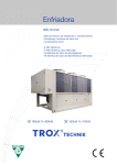
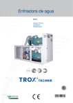
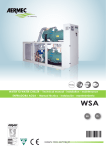
Download Chillers Aermec NRC - NRCH Installation Manual
Transcript
Español p. 23 English p. 02 INSTALLATION MANUAL MANUAL INSTALACIÓN Air / water chillers and heat pumps and condensing units with scroll compressors. Enfriadoras y bombas de calor aire agua y motocondensadores con compresores scroll. NRC INRCIV 0705 45726.04_00 INSTRUCTIONS FOR THE INSTALLER 1 3 4 5 6 7 8 Declaration of conformity ..............................................................................................................................................................................pag. Receiving the product......................................................................................................................................................................................pag. 1.1 Handling .........................................................................................................................................................................................pag. 1.2 Location ..........................................................................................................................................................................................pag. 1.2.1 Example of handling...................................................................................................................................................................pag. 1.3 Minimum technical clearances............................................................................................................................................pag. 2 Anti-vibration device position ................................................................................................................................................................pag. 2.1 Layout of positioning and diameter of anti-vibration fixing holes ..........................................................................pag. 2.2 Anti-vibration device position .................................................................................................................................................pag. Hydraulic circuit .................................................................................................................................................................................................pag. 3.1 Internal hydraulic circuit (standard equipment) ..........................................................................................................pag. 3.2 Preliminary operations Hydraulic circuit .........................................................................................................................pag. 3.2.1 Hydraulic circuit internal NRC (°) ........................................................................................................................................pag. 3.2.2 Hydraulic circuit internal NRC with storage tank ........................................................................................................pag. 3.2.3 Hydraulic circuit internal NRC with pump .......................................................................................................................pag. 3.3 Recommended external hydraulic circuit........................................................................................................................pag. 3.4 Start-up of the hydraulic circuit ..........................................................................................................................................pag. 3.5 External hydraulic circuit, standard (00) .........................................................................................................................pag. 3.6 External hydraulic circuit, pumps only (P1-P2-P3-P4) ...............................................................................................pag. 3.7 External hydraulic circuit, with storage tank (01 - 02 - 03 - 04 - 05 -06 -07 -08 ) .....................................pag. 3.8 Filter characteristics ................................................................................................................................................................pag. Position of plumbing connections ...............................................................................................................................................................pag. 4.1 Positions of plumbing connections NRC 0275 - 0300 - 0325 - 0350 - 0500 - 0550.............................pag. 4.2 Positions of plumbing connections NRC 0275 - 0300 - 0325 - 0350 - 0500 - 0550 ..............................pag. 4.3 Positions of plumbing connections NRC 0600 - 0650 -0700 - 0750 ...............................................................pag. 4.4 Positions of plumbing connections NRC 0600 - 0650 - 0700 - 0750 ..............................................................pag. 4.5 Positions of plumbing connections NRC 0800 - 0900 - 1000 .............................................................................pag. 4.6 Positions of plumbing connections NRC 0800 - 0900 - 1000 .............................................................................pag. Position of air delivery / pickup ...................................................................................................................................................................pag. 5.1 Variation of the fan speed .....................................................................................................................................................pag. Electrical wirings ................................................................................................................................................................................................pag. 6.1 Electrical data.............................................................................................................................................................................pag. Start-up ...................................................................................................................................................................................................................... pag. 7.1 Preliminary operations ....................................................................................................................................................................... pag. 7.1.1 Electrical checks.................................................................................................................................................................................... pag. 7.1.2 Hydraulic circuit checks .................................................................................................................................................................... pag. 7.2 Start-up ..................................................................................................................................................................................................... pag. 7.2.1 Refrigerating circuit checks ............................................................................................................................................................. pag. 7.2.2 Overheating ............................................................................................................................................................................................. pag. 7.2.3 Under-cooling .......................................................................................................................................................................................... pag. 7.2.4 Delivery temperature .......................................................................................................................................................................... pag. 7.3 Filling and draining the system........................................................................................................................................................ pag. Incorrect use ................................................................................................................................................................................................................... pag. 8.1 Important safety information........................................................................................................................................................... pag. 2 3 3 3 3 4 4 4 5 6 6 6 6 7 7 8 8 8 9 9 10 11 11 12 13 14 15 16 17 18 19 19 19 19 19 19 20 20 20 20 20 20 21 21 Dear Customer, Thank you for choosing AERMEC. It is the fruit of many years of experience and special design studies and has been made of the highest grade materials and with cutting edge technology. In addition, all our products bear the EC mark indicating that they meet the requirements of the European Machine Directive regarding safety. The standard of quality is permanently being monitored and AERMEC products are therefore a synonym for Safety, Quality and Reliability. The data may undergo modifications considered necessary for the improvement of the product, at any time and without the obligation for any notice thereof. Thank you again. AERMEC S.p.A AERMEC S.p.A. I-37040 Bevilacqua (VR) Italia – Via Roma, 44 Tel. (+39) 0442 633111 Telefax 0442 93730 – (+39) 0442 93566 www .aermec. com - info @ aermec. com NRC NRC H SERIAL NUMBER: DECLARATION OF CONFORMITY We, the undersigned, declare on our own exclusive responsibility that the object in question, so defined: NAME NRC TYPE AIR / WATER CHILLER, HEAT PUMP NRC RANGE MODEL The model this declaration refers to complies with the following harmonised standards: CEI EN 61000-6-2 CEI EN 61000-6-4 Immunity and electromagnetic emissions for industrial environments EN378 Refrigerating system and heat pumps - Safety and environmental requirements EN12735 Copper and copper alloys - Seamless, round copper tubes for air conditioning and refrigeration UNI1285-68 Calculation of the strength of metal pipes subjected to internal pressure EN60204-1 Machinery safety - Electrical equipment of machinery Thus also complying with the basic requirements of the following directives: - LVD Directive: 2006/95/CE - Electromagnetic compatibility directive 2004/108/CE - Machine Directive 98/37/CE - PED Directive regarding pressure-operated equipment 97/23/CE The product, pursuant Directive 97/23/EC, meets the Total Quality Warranty procedure (module H) with the certificate No. 06/270-QT3664, Rev.0 issued by the notified body No. 1131 CEC via Pisacane 46 Legnano (MI) - Itally Bevilacqua 26/03/2007 Marketing Director Signature 2 1 1.1 HANDLING Before moving the unit, examine the dimensions, weights, centre of mass and lifting points, then check that the equipment for lifting and positioning is suitable and complies with safety regulations currently in force. Particular attention must be paid to all the loading, unloading and lifting operations so as to avoid hazardous situations for people and damage to the structure and operational parts of the machine. IT IS absolutely forbidden to leave objects on the unit. Personnel engaged in handling the machine must have the proper personal protection devices. Under no circumstances must anybody or anything stop under the unit, even briefly. - Check that the cables are typeapproved to support the weight of the unit, and make sure they are RECEIVING THE PRODUCT well fixed. - The lifting frame must have the lifting point on the vertical of the centre of mass (the axes of the centre of mass are indicated by adhesive labels on the base). During lifting you are advised to fit antivibration mounts, fixing them to the holes on the base unit in accordance with the assembly layout supplied with the accessories (VT-AVX). 1.2 LOCATION Machines of the NRC series must be installed indoors, in a suitable area. This means installation with the necessary technical clearances. This is essential, both to allow routine and extraordinary maintenance interventions, and for operational needs, as the device must gather air from the outside, along the perimetric sides, and expel it upwards. For the correct working of the unit, it must be installed on a perfectly horizontal surface. Make sure that the resting surface is able to bear the weight of the machine. The device is made of galvanised steel sheet and hot painted with polyester powders to resist bad weather. This means that no particular measures have to be taken to protect the unit. NOTE: the device must be installed in such a way as to make all maintenance and/ or repair operations possible. The warranty of the device does not in any case cover costs incurred as a result of motorised ladders, scaffolding or any other lifting systems made necessary to carry out the operations under warranty. 1.2.1 Example of handling The diameter of the lifting holes is 40 mm 3 1.3 MINIMUM TECHNICAL CLEARANCES [mm] NRC 0275 NRC 0300 NRC 0325 NRC 0350 NRC 0500 NRC 0550 NRC 0600 NRC 0650 NRC 0700 NRC 0750 NRC 0800 NRC 0900 NRC 1000 A 1100 1100 1100 1100 1100 1100 1100 1100 1100 1100 1100 1100 1100 B 800 800 800 800 800 800 800 800 800 800 800 800 800 C 800 800 800 800 800 800 800 800 800 800 800 800 800 D 800 800 800 800 800 800 800 800 800 800 800 800 800 C D B A ANTI-VIBRATION DEVICE POSITION 2 2.1 LAYOUT OF POSITIONING AND DIAMETER OF ANTI-VIBRATION FIXING HOLES =gjgÛ\aÛ^akkY__agÛ Anti-vibration fixing hole Yfla¤naZjYfla 8 : >q Centre of mass 9Yja[]fljg 9 ; >p =gjgÛ\aÛ^akkY__agÛ Anti-vibration fixing hole Yfla¤naZjYfla < = ; >q 9Yja[]fljg Centre of mass 8 : 9 >p =gjgÛ\aÛ^akkY__agÛ Anti-vibration fixing hole Yfla¤naZjYfla : 8 < > = ? >q Centre of mass 9Yja[]fljg 9 ; >p 4 MODEL Ø HOLES (mm) 0275 Ø 16 0300 Ø 16 0325 Ø 16 0350 Ø 16 0500 Ø 16 0550 Ø 16 0600 Ø 16 0650 Ø 16 0700 Ø 16 0750 Ø 16 0800 Ø 18 0900 Ø 18 1000 Ø 18 2.2 ANTI-VIBRATION DEVICE POSITION STANDARD VERSION (°) NRC WEIGHT CENTRE OF MASS Gx Gy kg. 0275 679 1132 390 0300 715 1142 389 0325 749 1124 388 0350 827 1310 398 0500 954 1279 396 0550 969 1279 396 0600 1531 1883 493 0650 1548 1891 490 0700 1787 2193 493 0750 1968 2206 496 0800 2720 2233 480 0900 2750 2236 482 1000 3010 2259 466 ANTI-VIBRATION DEVICE POSITION A B C D E F • • • • • • • • • • • • • • • • • • • • • • • • • • • • • • • • • • • • • • • • • • • • • • • • • • • • • • • • • • • • • • VERSION WITH STORAGE TANK (01 - 08) (2) 0275 1327 1425 407 • • • • 0300 1391 1420 405 • • • • 0325 1401 1395 405 • • • • 0350 1496 1579 430 • • • • 0500 1621 1518 409 • • • • 0550 1638 1518 409 • • • • 0600 2243 2203 507 • • • • • • 0650 2260 2203 505 • • • • • • 0700 2498 2535 505 • • • • • • 0750 2680 2518 507 • • • • • • 0800 3770 2476 503 • • • • • • 0900 3800 2476 505 • • • • • • 1000 4050 2479 489 • • • • • • HEAT PUMP VERSION (H) WITHOUT STORAGE TANK 0275 739 1108 402 • • • • 0300 787 1126 396 • • • • 0325 798 1098 398 • • • • 0350 891 1300 431 • • • • 0500 983 1271 411 • • • • 0550 1049 1271 411 • • • • 0600 1643 1883 506 • • • • 0650 1660 1886 504 • • • • 0700 1881 2187 504 • • • • • • 0750 2051 2200 503 • • • • • • 0800 2847 2244 487 • • • • • • 0900 2877 2247 489 • • • • • • 1000 3145 2268 473 • • • • • • HEAT PUMP VERSION WITH STORAGE TANK (2) 0275 1365 1396 418 • • • • 0300 1420 1396 411 • • • • 0325 1430 1396 412 • • • • 0350 1530 1565 439 • • • • 0500 1694 1503 420 • • • • 0550 1710 1503 420 • • • • 0600 2355 2036 518 • • • • • • 0650 2372 2187 515 • • • • • • 0700 2593 2515 514 • • • • • • 0750 2763 2502 513 • • • • • • 0800 3890 2475 508 • • • • • • 0900 3920 2475 509 • • • • • • 1000 4182 2476 493 • • • • • • G • • • • • • • • • • • • H VT/AVX - KIT • • • VT2 VT2 VT2 VT2 VT17 VT17 AVX401 AVX401 AVX402 AVX402 AVX404 AVX404 AVX405 • • • VT16 VT16 VT16 VT14 VT14 VT14 AVX402 AVX402 AVX403 AVX403 AVX406 AVX406 AVX407 • • • VT2 VT2 VT2 VT2 VT17 VT17 AVX401 AVX401 AVX402 AVX402 AVX404 AVX404 AVX405 • • • VT16 VT16 VT16 VT14 VT14 VT14 AVX402 AVX402 AVX403 AVX403 AVX406 AVX406 AVX407 Weights and centres of mass referring to the model 00, full of water (2) = Weights and centres of mass referring to the model with storage tank 04. Models 0800- 0900- 1000 use a 700 litre storage tank. NOTE: For the position of the anti-vibration devices in the silenced versions, refer to the standard version (°). 5 3 3.1 INTERNAL HYDRAULIC CIRCUIT (standard equipment) - The unit is supplied in the various versions of: – “Standard NRC 00 (only evaporators, without hydronic kit) - Plate heat exchanger - Filter supplied - Differentual pressure switch – “NRC 01/02/03/04/05/06/07/08" (storage tank, high or low pressure pump with reserve pump option)” - Plate heat exchanger Filter assembled Expansion tanks (1 in the models from 0275 to 0750; 2 in the models from 0800 to 1000) Expansion vessel Buffer tank Pumps (1 or 1+1 reserve, high or low pressure Bleed valve Flow switch automatic feeding Safety valve – “NRC P1/P2/P3/P4 (only high or low pressure pump with reserve pump option)” - Plate heat exchanger - Filter supplied - Expansion vessel - Pumps (1 or 1+1 reserve, high or low pressure - Flow switch - automatic feeding HYDRAULIC CIRCUIT 3.2 PRELIMINARY OPERATIONS HYDRAULIC CIRCUIT Flow switch Safety valve Bleed valve NOTES The presence of the filter should be considered obligatory, and its removal will make the guarantee VOID. IT MUST BE KEPT CLEAN, SO IT IS NECESSARY TO CHECK ITS CLEAN STATE AFTER THE INSTALLATION OF THE UNIT, AND CHECK IT REGULARLY. WARNING: for sizes 0800-09001000, the filter is supplied for all the versions. Before connecting the chiller, it is a good idea to run water through the pipes to eliminate any foreign bodies that could jeopardise the good working of the device. When making the hydraulic connections, check that the indications in the chapter "Hydraulic connections" are respected. It is a good idea to ensure that the connections can be easily disconnected by means of pipe unions with rotating couplings. The installation of the manual interception valves between the unit and the rest of the system should be considered obligatory for all NRC models (with and without storage tank) and for all the hydraulic circuits that concern the chiller itself (desuperheaters, total recovery): if this is not done, the guarantee will be considered void. All the flow switches in the NRC units have been factory-calibrated for correct working with a nominal water flow rate. In the vast majority of cases, this means no additional operations are necessary. All the heat exchangers are fitted with an electric heater. The parallel water connections are to be made by the installation engineer. 3.2.1 Hydraulic circuit internal NRC (°) 1 A EV 2 B KEY 1 - Water filter; 2 - Differential pressure switch; 6 EV - Evaporator circuit; A - Water inlet; B - Water outlet; 3.2.2 Hydraulic circuit internal NRC with storage tank (01/02/03/04/05/06/07/08) 8 3 5 2 1 A EV 6 4 7 KEY B 5 - Expansion vessel; 6 - Bleed valve 7 - Storage tank; 8 - Filler assebly with pressure gauge; 1 - Water filter; 2 - Flow switch; 3 - Pump assembly; 4 - Safety valve; EV - Evaporator circuit; SAC - Accumulator probe A - Water inlet; B - Water outlet; NB: in the versions 0800 - 0900 -1000, the water filter is supplied. 3.2.3 Hydraulic circuit internal NRC with pump (P1/P1/P3/P4) 8 3 EV 6 1 2 5 4 Rough section assembly supplied KEY 1 - Water filter; 2 - Flow switch; 3 - Pump assembly; 4 - Safety valve; 5 - Expansion vessel; 6 - Bleed valve 8 - Filler assebly with pressure gauge; EV - Evaporator circuit; A - Water inlet; B - Water outlet; 7 3.3 RECOMMENDED EXTERNAL HYDRAULIC CIRCUIT For the NRC models without storage tank, the installation of the following system accessories is recommended (see figure 3.5): - Storage tank. - The filter is an essential component for the machine to work well.In the basic and heat pump versions the filter is supplied (so the assembly is the responsibility of the customer), while for the other versions it is assembled in the factory; - Manual interception valves between the unit and the rest of the system (compulsory), to facilitate maintenance operations and avoid discharging the whole system; - Drain valve; - Automatic system power supply with pressure gauge; - Safety valve. - Expansion tank - Pumping unit For the NRC models fitted only with a pump unit, the installation of the following system accessories is recommended (see figure 3.6): - Storage tank. - manual interception valves between the unit and the rest of the system - (compulsory), to facilitate maintenance operations and avoid discharging the whole system; Drain valve; Automatic system power supply with pressure gauge; Safety valve. Expansion tank For the NRC models fitted with an storage tank on the other hand, the installation of manual interception valves is recommended, between the unit and the rest of the system (compulsory), to facilitate maintenance operations and avoid discharging the whole system; These considerations should be extended to the hydraulic circuits of the desuperheaters (or total recovery) as well, for the NRC models that offer these solutions. Note The hydraulic piping for connection to the machine must be properly scaled for the actual water flow rate required by the plant when working. The water flow rate to the heat exchanger must always be constant. 3.4 START-UP OF THE HYDRAULIC CIRCUIT - Before starting up the machine, check that all the hydraulic connections have been correctly made, and that the indications on the plates have been observed. - Check that the hydraulic system is full and under pressure, and check also that there is no air (if there is air, bleed it). - Check that any interception valves on the system are correctly opened. - Check that the circulation pump(s) are working, and that the water flow rate is sufficient to close the flow switch contact. - Check the water flow rate, measuring the difference of pressure between the evaporator inlets and outlets, and then calculate the rate with the "Evaporator pressure drops" diagram in the Aermec documentation. - Check the correct working of the flow switch: by closing the interception valve at the heat exchanger outlet, the unit must visualise the block. Reopen the valve and rearm the block. These considerations should be extended to the hydraulic circuits of the desuperheaters (or total recovery) as well, for the NRC models that offer these solutions. 3.5 NRC EXTERNAL HYDRAULIC CIRCUIT, STANDARD (00) supplied filter 1 2 3 4 A 6 5 7 8 KEY 1 - Water filter (filter supplied) 2 - Flexible joint; 3 - Manual interception valve; 4 - Pump assembly; 5 - Safety valve; 6 - Expansion tank; 8 9 7 - Drain valve; 8 - Storage tank; 9 - Automatic power supply with pressure gauge; A - Water inlet; B - Water outlet; B 3.6 NRC EXTERNAL HYDRAULIC CIRCUIT, PUMPS ONLY (P1-P2-P3-P4) ~ 8 9 KEY 1 - Water filter (supplied) 2 - Manual interception valve 3 - Storage tank A - Water inlet B - Water outlet; 3.7 NRC EXTERNAL HYDRAULIC CIRCUIT, WITH STORAGE TANK (01 - 02 - 03 - 04 - 05 -06 -07 -08 ) ~ 8 9 KEY 1 - FILTER SUPPLIED ONLY WITH SIZES 0800 - 0900 - 1000, for the other sizes, the filter is already assembled inside the unit. 2 - Manual interception valve. 9 3.8 FILTER CHARACTERISTICS MODELS 0275 - 0300 - 0325 - 0350 - 0500 - 0550 - 0600 0650 - 0700 - 0750 0275 - 0300 - 0325 - 0350 - 0500 - 0550 - 0600 0650 - 0700 - 0750 CHARACTERISTICS Ø gas : 2" 1/2 Ø hole inscribed: 600 micron number of holes per sq.cm: 53 with partial recovery desuperheater Filter on the circuit of the desuperheater: Ø gas: 1" 1/2 Ø hole inscribed: 500 micron number of holes per sq.cm: 80 Hydraulic circuit filter: Ø gas: 2" 1/2 Ø hole inscribed: 600 micron number of holes per sq.cm: 53 0275 - 0300 - 0325 - 0350 - 0500 - 0550 - 0600 0650 - 0700 - 0750 with total recovery desuperheater Filter on the total recovery: Ø gas: 2" 1/2 Ø hole inscribed: 600 micron number of holes per sq.cm: 53 Hydraulic circuit filter: Ø gas: 2" 1/2 Ø hole inscribed: 600 micron number of holes per sq.cm: 53 0800 - 0900 - 1000 0800 - 0900 -1000 Ø nominal: 80 mm Ø hole inscribed: 1600 micron number of holes per sq.cm: 22 with total recovery desuperheater Total recovery filter Ø nominal: 80 mm Ø hole inscribed: 1600 micron number of holes per sq.cm: 22 Hydraulic circuit filter Ø nominal: 80 mm Ø hole inscribed: 1600 micron number of holes per sq.cm: 22 10 4 4.1 POSITION OF PLUMBING CONNECTIONS POSITIONS OF PLUMBING CONNECTIONS NRC 0275 - 0300 - 0325 - 0350 - 0500 - 0550 Standard / H versions, and pump Power supply Condensate drain 1/2" Gas Coil side (seen(vista fromdall’ above) Lato batterìa alto) RIGHT-HAND SIDE OF MACHINE The position and the type of plumbing connections change according to the version: basic version (filter supplied): IN (3) - OUT (2); ø 2” M pump version: IN (1) - OUT (2); ø 2” 1/2 F Position A B 0275 mm 1172 1088 0300 mm 1372 1288 0325 mm 1372 1288 0350 mm 1372 1288 0500 mm 1572 1488 0550 mm 1572 1488 DIAMETERS OF PLUMBING CONNECTIONS FOR VERSIONS WITH RECOVERY Y Z Versions with recovery [ a OUTPUT tot. rec. ø 2” Gas Male b OUTPUT desup. ø 1” Gas Male c INPUT desup ø 1” Gas Male d INPUT tot. rec. ø 2” Gas Male e Loading input ø 1/2" Gas \ ] tot. rec. = total recovery desup. = desuperheater 11 4.2 POSITIONS OF PLUMBING CONNECTIONS NRC 0275 - 0300 - 0325 - 0350 - 0500 - 0550 Standard / H versions, and pump with storage tank Coil side (seen(vista fromdall’ above) Lato batterìa alto) Storage tank accumulo Remember that the positioning of the outputs for the electrical power supply and condensate drain (for versions with storage tank) are the same as those for standard versions (shown on the previous page). Position A B 0275 mm 1172 1088 0300 mm 1372 1288 0325 mm 1372 1288 0350 mm 1372 1288 0500 mm 1572 1488 0550 mm 1572 1488 RIGHT-HAND SIDE OF MACHINE DIAMETERS OF PLUMBING CONNECTIONS FOR VERSIONS WITH RECOVERY Y Z Versions with recovery a OUTPUT tot. rec b OUTPUT desup. Ø1" Gas Male c INPUT desup. Ø 1"Gas Male d INPUT tot. rec. Ø 2" Gas Male e Loading input Ø 1/2" Gas tot. rec. = total recovery desup. = desuperheater 12 [ Ø2 " Gas Male \ ] 4.3 POSITIONS OF PLUMBING CONNECTIONS NRC 0600 - 0650 - 0700 - 0750 Standard / H versions, and pump Power supply Power supply Condensate drain 1/2" gas ~ (vistaabove) dall’ alto) CoilLato sidebatterìa (seen from RIGHT-HAND SIDE OF MACHINE ~ Position A B 0600 mm 1698 1782 0650 mm 1698 1782 0700 mm 1698 1782 0750 mm 1698 1782 @EÛ¨© ~ FLKÛ¨© ~ 8 9 ~ @EÛ¨~© The position and the type of plumbing connections change according to the version: basic version (filter supplied): IN (3) - OUT (2); ø 2” M pump version: IN (1) - OUT (2); ø 2” 1/2 F DIAMETERS OF PLUMBING CONNECTIONS FOR VERSIONS WITH RECOVERY Y Z [ \ Versions with recovery OUTPUT tot. rec. Ø 2" Gas Male b OUTPUT desup. Ø 1" Gas Male c INPUT desup Ø 1" Gas Male d INPUT tot. rec Ø 2" Gas Male e Loading input Ø 1/2" Gas a ] tot. rec. = total recovery desup. = desuperheater 13 4.4 POSITIONS OF PLUMBING CONNECTIONS NRC 0600 - 0650 - 0700 - 0750 Standard / H versions, and pump with storage tank Power supply Power supply Condensate drain 1/2" gas RIGHT-HAND SIDE OF MACHINE Position A B 0600 mm 1698 1782 0650 mm 1698 1782 0700 mm 1698 1782 0750 mm 1698 1782 DIAMETERS OF PLUMBING CONNECTIONS FOR VERSIONS WITH RECOVERY Coil (seen from Latoside batterìa (vista dall’above) alto) accumulo Remember that the positioning of the outputs for the electrical power supply and condensate drain (for versions with storage tank) are the same as those for standard versions (shown on the previous page).. a b c Versions with recovery a OUTPUT tot. rec. Ø 2" Gas Male b OUTPUT desup. Ø 1" Gas Male c INPUT desup. Ø 1" Gas Male d INPUT tot. rec. Ø 2" Gas Male e Loading input Ø 1/2" Gas tot. rec. = total recovery desup. = desuperheater 14 storage tank d e POSITIONS OF PLUMBING CONNECTIONS NRC 0800 - 0900 - 1000 Standard / H versions, and pump 237 100 The position and the type of plumbing connections change according to the version: basic version (supplied filter): IN (3) - OUT (2); ø 3” Vitaulic pump version (supplied filter): IN (1) - OUT (2); ø 3” Victaulic For models 0800-0900-1000, the water filter is always supplied; its assembly is therefore the responsibility of the user a b c d e DIAMETERS OF PLUMBING CONNECTIONS FOR VERSIONS WITH RECOVERY RIGHT-HAND SIDE OF MACHINE Ø 2" Gas Male b INPUT desup. Ø 2" Gas Male c Loading input Ø 1/2" Gas d OUTPUT tot. rec. Ø 3" Victaulic e INPUT tot. rec. Ø 3" Victaulic IN (3) Coil side from above) Lato (seen batterìa (vista dall’ alto) OUT (2) 268 174 712 1100 tot. rec. = total recovery desup. = desuperheater 100 140 OUTPUT desup. 140 a 519 Versions with recovery 1673 4.5 IN (1) 145 140 125 15 4.6 POSITIONS OF PLUMBING CONNECTIONS NRC 0800 - 0900 - 1000 Standard / H versions, and pump with storage tank Remember that the positioning of the outputs for the electrical power supply and condensate drain (for versions with storage tank) are the same as those for standard versions (shown on the previous page). For models 0800-0900-1000, the water filter is always supplied; its assembly is therefore the responsibility of the user. RIGHT-HAND SIDE OF MACHINE Versions with recovery a OUTPUT desup. Ø 2" 1/2 Gas Female b INPUT desup. Ø 2" 1/2 Gas Female c Loading input Ø 1/2" Gas d OUTPUT tot. rec. Ø 3" Victaulic e INPUT tot. rec. Ø 3" Victaulic tot. rec. = total recovery desup. = desuperheater OUT 3" VICTAULIC IN 3" VICTAULIC CoilLato sidebatterìa (seen from (vista above) dall’ alto) 16 storage tank accumulo POSITION OF AIR DELIVERY / PICKUP ; Y < 5 9 8 : 9 X NRC 0275 - 0550 STANDARD / WITH STORAGE TANK (mm) A B C D 0275 471 496 351 52 0300 471 456 392 52 0325 471 456 392 52 0350 517 576 428 45 0500 517 576 428 45 0550 517 576 428 45 COIL DIMENSIONS (mm) 0275 0300 0325 0350 X 1800 1800 1800 2200 Y 1450 1650 1650 1650 E 429 503 503 491 491 491 0550 2200 1850 < = Y 333 88 0500 2200 1850 9 8 : 9 ; 9 X NRC 0600 - 0750 STANDARD /WITH STORAGE TANK (mm) NRC A B C D 0600 597 577 428 510 0650 597 577 428 510 0700 877 577 705 655 0750 877 577 705 655 COIL DIMENSIONS (mm) 0600 0650 0700 0750 X 3300 3300 4100 4100 Y 1600 1600 1600 1600 F 333 333 333 333 < = Y 333 85 E 137 137 137 137 8 9 : 9 ; 9 : 9 X NRC 0800 - 1000 STANDARD/ WITH STORAGE TANK (mm) NRC A B C D 0800 698 577 430 481 0900 698 577 430 481 1000 698 577 430 481 COIL DIMENSIONS (mm) 0800 0900 1000 X 4500 4500 4500 Y 1600 1600 1600 E 281 281 281 F 333 333 333 NB: the positioning of the air delivery / pickup points are valid for versions with or without storage tank. 17 5.1 VARIATION OF THE FAN SPEED To set the ventilation static pressure to the installation needs, it is necessary to change the fan speed as follows: 1) remove the front panel; 2) loosen the belt by adjusting the regulation (B) with a proper tool; 3) remove the belt 4) loosen the lock (A) by means of a wrench and turn the movable part of the pulley to obtain the required diameter; 5) tighten the lock (A); 6) replace the belt, adjust its tension by using the relevant regulation (B) 7) replace the panel The units are normally shipped with pulley set to obtain the nominal flow rate with no static pressure, if not otherwise requested. To perform an accurate setting check the fan shaft speed with a proper instrument. 18 A B 6 The unit is fully wired in the factory and, for the start-up, requires a power supply as shown in the indications on the unit's rating plate, with online protective cut-outs. The cable cross sections and the dimensions of the line main switch are purely indicative. The installer will be responsible for properly scaling the power line with regards to the length and type of cable, the input power of the unit and the physical positioning. ELECTRICAL WIRINGS All the electrical connections must comply with the regulations in force at the time of the installation. The layouts given in this documentation must only be used as an aid for the setting up of the electrical lines. For installation requirements, refer to the wiring layout supplied with the device. Note: Check that all power cables are correctly secured to the terminals when switched on for the first time and after 30 days of use. Afterwards, check the connection of the power cables every six months. Slack terminals could cause the cables and components to overheat. Cross section recommended for the maximum length of 50m. The cross section of the cable and the dimensions of the line main switch are purely indicative. 6.1 ELECTRICAL DATA Size 0275 0300 0325 0350 0500 0550 0600 0650 0700 0750 0800 0900 1000 Sect. A (mm2) 25 25 35 35 50 50 70 70 95 95 120 150 150 Sect. B (mm2) 1,5 1,5 1,5 1,5 1,5 1,5 1,5 1,5 1,5 1,5 1,5 1,5 1,5 Sect. PE (mm2) 16 16 16 16 25 25 35 35 50 50 70 70 95 IL (A) 80 80 100 100 125 125 200 200 200 250 250 315 315 KEY Sect. A = Line Sect. B = Remote safety Sect. PE = Earth commands IL = Main switch 7 7.1 PRELIMINARY OPERATIONS WARNING Before carrying out the controls indicated below, ensure that the unit is disconnected from the mains supply. Ensure that the main switch is turned to OFF and locked in position, and attach a warning sign to the switch. Before beginning the operations, check the absence of voltage by means of a voltmeter or a phase detector. 7.1.1 ELECTRICAL CHECKS - Check the general power supply cables are of a suitable section, able to withstand the overall absorption of the unit (see electrical data), and that the unit has been duly earthed. - Check all the electrical connections are correctly fixed and all the terminals adequately closed. The following operations must be carried out when the unit is powered up. START-UP - Power up the unit by turning the main switch to the ON position. The display will light up a few seconds after this. Check that the working status is positioned on OFF (OFF BY KEYB on the lower side of the display). - Use a tester to check that the value of the supply voltage at the RST phases is equal to 400V ±10%, and also check that the imbalance between the phases is not greater than 3%. - Check that the connections made by the installer comply with the data given here. - Check the heater(s) of the compressor carter are working by measuring the increase in temperature of the oil bowl. - The heater(s) must work for at least 24 hours before the compressor start-up, and in any case the temperature of the oil bowl must be 10-15°C higher than the room temperature. WARNING At least 24 hours before starting up the unit (or at the end of each period of prolonged inactivity) the unit must be powered up, to allow the heaters of the compressor carter to evaporate any refrigerant that may be present in the oil. If this precaution is not performed the compressor could be seriously damaged and the guarantee would no longer be valid. 7.1.2 HYDRAULIC CIRCUIT CHECKS - Check that all the hydraulic connections are correctly made and that the indications on the plates are observed. - Check that the hydraulic system is full and under pressure, and check also that there is no air (if there is air, bleed it). - Check that any interception valves on the system are correctly opened. - Check that the circulation pump(s) are working, and that the water flow rate is sufficient to close the flow switch contact. - Check the water flow rate, measuring 19 the difference of pressure between the evaporator inlets and outlets, and then calculate the rate with the "Evaporator pressure drops" diagram in the technical documentation. - Check the correct working of the flow switch/differential pressure switch by closing the interception valve at the heat exchanger outlet, the unit must visualise the block. Reopen the valve and rearm the block. 7.2 START-UP After carefully carrying out all the checks detailed above, it is possible to start up the unit by pressing the ON button. Check the set working parameters (setpoint) and rearm any alarms that may be present. After a few minutes, the unit will start up. - Check the rotation direction of the fans. If the rotation is not correct, switch off the main power supply and invert two of the three power supply cables on the main switch. Do not tamper with the connections inside the electrical cabinet. Doing so voids the guarantee. - Check the input current of the fans and the compressor, and compare it with the technical data in the technical documentation. NOTE: For the setting of all functional parameters and for detailed information regarding machine functioning and the control card, refer to the user's manual. 7.2.1 REFRIGERATING CIRCUIT CHECKS - Check for any refrigerating gas leaks, especially near the pressure gauge connection points, pressure transducers and pressure switches (vibration during transport may have loosened the connectors). - After a brief working period, check the level of oil in the compressor and the absence of bubbles in the liquid indicator glass. The continuous passage of vapour bubbles may indicate an insufficient refrigerant charge or that the thermostatic valve is incorrectly set. The presence of vapour for brief periods is, however, possible. 7.2.2 OVERHEATING Check the level of overheating by comparing the temperature indicated with a contact thermostat placed on the 20 compressor suction and the temperature shown on the low pressure gauge (saturation temperature corresponding to the evaporation pressure). The difference between these two temperatures gives the superheating value. Optimum values are between 4 and 8°C. 7.2.3 UNDER-COOLING Check the level of under-cooling by comparing the temperature indicated with a contact thermostat placed on the tube at the condenser outlet and the temperature shown on the high pressure gauge (saturation temperature corresponding to the condensation pressure). The difference between these two temperatures gives the under-cooling value. Optimum values are between 4 and 5°C. 7.2.4 DELIVERY TEMPERATURE If the values of under-cooling and overheating are regular, the temperature measured in the delivery tube at the compressor outlet must be 30/40°C higher than the condensation temperature. 7.3 FILLING AND DRAINING THE SYSTEM During the winter, if the system remains idle, the water in the heat exchanger may freeze, causing irreparable damage to the heat exchanger itself, the complete draining of the refrigerating circuits and, sometimes, damage to the compressors. To avoid the risk of freezing, there are three possible solutions: - the complete draining of the water from the heat exchanger at the end of the season, and the refilling at the start of the next season, by means of the drain valve located on the storage tank in the versions with storage tank and/or pump. - the operation with glycol water, with a glycol percentage chosen on the basis of the minimum outside temperature envisaged. In this case, it is necessary to take into consideration the different yields and absorption of the chiller, the measurements of the pumps and the output of the terminals. - the use of heaters in the heat exchanger (standard on all devices). In this case the heaters must always be powered for the entire winter period (machine in standby). 8 The device is designed and built to ensure the maximum safety in its immediate vicinity (IP24) as well as to resist atmospheric agents. The fans have protection grilles to prevent the unwanted intrusion of foreign bodies. The accidental opening of the electric panel with the machine in operation is prevented by the door lock sectioning device. Do not rest tools or heavy objects directly on the side heat exchanger coils, so as not to ruin the fins. NOTE Do not introduce objects or allow them to fall through the grilles of the fan motors. Do not rest cutting surfaces against the thermal exchange coils. 8.1 IMPORTANT SAFETY INFORMATION The machine must not exceed the pressure INCORRECT USE and temperature limits indicated in the table given in the “Operating limits” paragraph of the technical manual. Correct functioning is not guaranteed after a fire; before starting up the machine again, contact an authorised Assistance Centre. The machine is equipped with safety valves which, in the event of excessive pressure, can discharge the high temperature gases into the atmosphere. Wind, earthquakes and other natural phenomena of exceptional intensity have not been taken into account. If the unit is used in an aggressive atmosphere or with aggressive water, consult the company headquarters. carry out the following operations: - pay the greatest attention in restoring the load of refrigerant as indicated on the machine plate (inside the electric panel) - open all the taps in the refrigerating circuit - correctly connect the power supply and the earthing - check the hydraulic connections - check the water pump is working correctly - clean the water filters - check the condenser coils are not dirty or obstructed - check the correct rotation of the fan unit WARNING Following extraordinary maintenance interventions on the refrigerating circuit, with the replacement of components, before restarting the machine it is necessary to Danger: Temperature Danger: Cut off the power Danger: Voltage Danger: Moving parts Danger!!! 21 INSTRUCCIONES PARA EL INSTALADOR 1 3 3.5 4 5 6 7 8 Declaración de conformidad ........................................................................................................................................................................pag. Recepción del producto ..................................................................................................................................................................................pag. 1.1 Desplazamiento ..........................................................................................................................................................................pag. 1.2 Ubicación .......................................................................................................................................................................................pag. 1.2.1 Ejemplo de desplazamiento ...................................................................................................................................................pag. 1.3 Espacios técnicos mínimos ...................................................................................................................................................pag. 2 Posición antivibradores...........................................................................................................................................................................pag. 2.1 Esquema de posición y diámetro de fijación antivibradores.. .................................................................................pag. 2.2 Posición antivibradores ...........................................................................................................................................................pag. Circuito hidráulico .............................................................................................................................................................................................pag. 3.1 Circuito hidráulico interno (equipamiento de serie)....................................................................................................pag. 3.2 Operaciones preliminares Circuito hidráulico ...............................................................................................................pag. 3.2.1 Circuito hidráulico interno NRC (°) ....................................................................................................................................pag. 3.2.2 Circuito hidráulico interno NRC con acumulación.......................................................................................................pag. 3.2.3 Circuito hidráulico interno NRC con bomba ..................................................................................................................pag. 3.3 Circuito hidráulico externo aconsejado ............................................................................................................................pag. 3.4 Start up circuito hidráulico ....................................................................................................................................................pag. Circuito hidráulico externo NRC estándar .....................................................................................................................................pag. 3.6 Circuito hidráulico externo NRC sólo bombas ..............................................................................................................pag. 3.7 Circuito hidráulico externo NRC con acumulación......................................................................................................pag. 3.8 Características de los filtros.................................................................................................................................................pag. Posición conexiones hidráulicas..................................................................................................................................................................pag. 4.1 Posición conexiones hidráulicas NRC 0275 - 0300 - 0325 - 0350 - 0500 - 0550 ...................................pag. 4.2 Posición conexiones hidráulicas NRC 0275 - 0300 - 0325 - 0350 - 0500 - 0550 ...................................pag. 4.3 Posición conexiones hidráulicas NRC 0600 - 0650 -0700 - 0750 ....................................................................pag. 4.4 Posición conexiones hidráulicas NRC 0600 - 0650 - 0700 - 0750 ...................................................................pag. 4.5 Posición conexiones hidráulicas NRC 0800 - 0900 - 1000...................................................................................pag. 4.6 Posición conexiones hidráulicas NRC 0800 - 0900 - 1000...................................................................................pag. Posición de envío / retorno de aire ..........................................................................................................................................................pag. 5.1 Variación del número de revoluciones del ventilador .................................................................................................pag. Conexiones eléctricas......................................................................................................................................................................................pag. Datos eléctricos ........................................................................................................................................................................pag. 6.1 Puesta en marcha ............................................................................................................................................................................................ pag. 7.1 Operaciones preliminares .............................................................................................................................................................. pag. 7.1.1 Controles eléctricos .......................................................................................................................................................................... pag. 7.1.2 Controles circuito hidráulico ......................................................................................................................................................... pag. 7.2 Puesta en marcha.............................................................................................................................................................................. pag. 7.2.1 Controles circuito de refrigeración ......................................................................................................................................... pag. 7.2.2 Sobrecalentamiento .......................................................................................................................................................................... pag. 7.2.3 Sobreenfriamiento ............................................................................................................................................................................. pag. 7.2.4 Temperatura de impulsión ............................................................................................................................................................. pag. 7.3 Carga / Descarga instalación ................................................................................................................................................... pag. Usos impropios............................................................................................................................................................................................................... pag. 8.1 Importantes informaciones de seguridad ............................................................................................................................. pag. 23 24 24 24 24 25 25 25 26 27 27 27 27 28 28 29 29 29 30 30 31 32 32 33 34 35 36 37 38 39 40 40 40 40 40 40 41 41 41 41 41 41 42 42 Estimado cliente, Le agradecemos su elección por un producto AERMEC. Este producto es el resultado de varios años de experiencia y de estudios de proyectación minuciosos, y ha sido construido con materiales de primera calidad y tecnología de vanguardia. Además, la marca CE garantiza que los aparatos cumplan los requisitos de la Directiva Europea Máquinas por lo que se refiere a la seguridad. Nuestro nivel de calidad está sometido a una vigilancia constante, por lo que los productos AERMEC son sinónimo de Seguridad, Calidad y Fiabilidad. Los datos pueden experimentar modificaciones que se consideren necesarias en cualquier momento y sin la obligación de aviso previo para la mejora del producto. Gracias de nuevo. AERMEC S.p.A AERMEC S.p.A. I-37040 Bevilacqua (VR) Italia – Via Roma, 44 Tel. (+39) 0442 633111 Telefax 0442 93730 – (+39) 0442 93566 www .aermec. com - info @ aermec. com NRC NRC H NÚMERO DE SERIE : DECLARACIÓN DE CONFORMIDAD Los que suscriben la presente declaran bajo la propia y exclusiva responsabilidad que el conjunto en objeto, definido como sigue: NOME NRC TIPO ENFRIADORA AIRE / AGUA, BOMBAS DE CALOR SERIE NRC MODELO Al que se refiere esta declaración es conforme a las siguientes normas armonizadas: CEI EN 61000-6-2 CEI EN 61000-6-4 Inmunidad y emisiones electromagnéticas para el ambiente industrial EN378 Refrigerating system and heat pumps - Safety and environmental requirements EN12735 Copper and copper alloys - Seamless, round copper tubes for air conditioning and refrigeration UNI1285-68 Cálculo de resistencia de los tubos metálicos sometidos a presión interna; EN60204-1 Seguridad de la maquinaria - Equipamiento eléctrico de las máquinas Satisfaciendo de este modo los requisitos esenciales de las siguientes directivas: - Directiva LVD: 2006/95/CE - Directiva compatibilidad electromagnética 2004/108/CE - Directiva máquinas 98/37/CE - Directiva PED en materia de equipos a presión 97/23/CE El producto, en conformidad con la directiva 97/23/CE, satisface el procedimiento de Garantía de Calidad Total (modulo H) con certificado n.06/270-QT3664 Rev.0 emitido por el organismo acreditado n.1131 CEC via Pisacane 46 Legnano (MI) - Itally Bevilacqua 26/03/2007 Director Comercial Firma 23 1 1.1 DESPLAZAMIENTO Antes de mover la unidad asegúrese bien de las dimensiones, pesos, baricentro, y puntos de levantamiento, compruebe luego que el equipamiento para realizar el levantamiento sea adecuado y respete las normas vigentes de seguridad. Hay que prestar una atención especial a las operaciones de carga, descarga y levantamiento para evitar situaciones peligrosas para las personas, daños a la carpintería y a los órganos funcionales de la máquina. Está absolutamente prohibido depositar objetos sobre la unidad. El personal encargado a la movilización de la unidad debe estar provisto de medios de protección individual adecuados. Está terminantemente prohibido detenerse debajo de la unidad - Asegúrese de que los cables estén homologados para soportar el peso RECEPCIÓN DEL PRODUCTO de la unidad, compruebe que estén bien fijados - El armazón de levantamiento debe tener el punto de enganche en la vertical del baricentro, los ejes del baricentro están indicados por etiquetas situadas en la base. Durante la elevación se aconseja montar los soportes antivibradores fijándolos en los orificios de la base según el esquema de montaje que acompaña a los accesorios (VT-AVX). sarlo hacia arriba. Para el correcto funcionamiento de la unidad, ésta deberá instalarse en un plano perfectamente horizontal. Asegúrese de que la superficie de apoyo pueda soportar el peso de la máquina. El aparato se ha realizado en chapa de acero galvanizada y tratada mediante barnizado en caliente con polvos de poliéster para resistir a la intemperie. Por tanto, no son necesarias medidas especiales para la protección de la unidad. 1.2 NOTA: El aparato debe instalarse de manera que sea posible llevar a cabo las operaciones de mantenimiento y/o reparación. En cualquier caso, la garantía del aparato no cubre los gastos debidos a autoescalas, andamios u otros sistemas de elevación que fueran necesarios para efectuar las intervenciones en garantía UBICACIÓN Las máquinas de la serie NRC deben instalarse en el exterior, en una zona adecuada, considerando los espacios técnicos necesarios. Esto es indispensable tanto para permitir las intervenciones de mantenimiento ordinario y extraordinario como para las exigencias de funcionamiento, ya que el aparato debe recoger aire del exterior a lo largo de los lados perimetrales y expul- 1.2.1 Ejemplo de desplazamiento El diámetro interior de los orificios de elevación es de 40 mm 24 1.3 ESPACIOS TÉCNICOS MÍNIMOS [mm] NRC 0275 NRC 0300 NRC 0325 NRC 0350 NRC 0500 NRC 0550 NRC 0600 NRC 0650 NRC 0700 NRC 0750 NRC 0800 NRC 0900 NRC 1000 A 1100 1100 1100 1100 1100 1100 1100 1100 1100 1100 1100 1100 1100 B 800 800 800 800 800 800 800 800 800 800 800 800 800 C 800 800 800 800 800 800 800 800 800 800 800 800 800 D 800 800 800 800 800 800 800 800 800 800 800 800 800 C D B A 2 POSICIÓN ANTIVIBRADORES 2.1 ESQUEMA DE POSICIÓN Y DIÁMETRO DE LOS ORIFICIOS DE FIJACIÓN ANTIVIBRADORES Orificio de fijación =gjgÛ\aÛ^akkY__agÛ antivibradores Yfla¤naZjYfla 8 : >q Centro de gravedad 9Yja[]fljg 9 ; >p Orificio de fijación =gjgÛ\aÛ^akkY__agÛ antivibradores Yfla¤naZjYfla < = ; Ø ORIFICIOS (mm) 0275 Ø 16 0300 Ø 16 0325 Ø 16 0350 Ø 16 0500 Ø 16 0550 Ø 16 0600 Ø 16 0650 Ø 16 0700 Ø 16 0750 Ø 16 0800 Ø 18 0900 Ø 18 1000 Ø 18 >q Centro de gravedad 9Yja[]fljg MODELO 8 : 9 >p Orificio de fijación =gjgÛ\aÛ^akkY__agÛ antivibradores Yfla¤naZjYfla : 8 < > >q Centro de gravedad 9Yja[]fljg 9 ; = ? >p 25 2.2 POSICIÓN ANTIVIBRADORES VERSIÓN ESTÁNDAR (°) NRC PESO CENTRO DE POSICIÓN ANTIVIBRADORES kg. GRAVEDAD Gx Gy A B C D E F 0275 679 1132 390 • • • • 0300 715 1142 389 • • • • 0325 749 1124 388 • • • • 0350 827 1310 398 • • • • 0500 954 1279 396 • • • • 0550 969 1279 396 • • • • 0600 1531 1883 493 • • • • 0650 1548 1891 490 • • • • 0700 1787 2193 493 • • • • • • 0750 1968 2206 496 • • • • • • 0800 2720 2233 480 • • • • • • 0900 2750 2236 482 • • • • • • 1000 3010 2259 466 • • • • • • VERSIÓN CON ACUMULACIÓN (01 - 08) (2) 0275 1327 1425 407 • • • • 0300 1391 1420 405 • • • • 0325 1401 1395 405 • • • • 0350 1496 1579 430 • • • • 0500 1621 1518 409 • • • • 0550 1638 1518 409 • • • • 0600 2243 2203 507 • • • • • • 0650 2260 2203 505 • • • • • • 0700 2498 2535 505 • • • • • • 0750 2680 2518 507 • • • • • • 0800 3770 2476 503 • • • • • • 0900 3800 2476 505 • • • • • • 1000 4050 2479 489 • • • • • • VERSIÓN BOMBA DE CALOR (H) SIN ACUMULACIÓN 0275 739 1108 402 • • • • 0300 787 1126 396 • • • • 0325 798 1098 398 • • • • 0350 891 1300 431 • • • • 0500 983 1271 411 • • • • 0550 1049 1271 411 • • • • 0600 1643 1883 506 • • • • 0650 1660 1886 504 • • • • 0700 1881 2187 504 • • • • • • 0750 2051 2200 503 • • • • • • 0800 2847 2244 487 • • • • • • 0900 2877 2247 489 • • • • • • 1000 3145 2268 473 • • • • • • VERSIÓN BOMBA DE CALOR CON ACUMULACIÓN (2) 0275 1365 1396 418 • • • • 0300 1420 1396 411 • • • • 0325 1430 1396 412 • • • • 0350 1530 1565 439 • • • • 0500 1694 1503 420 • • • • 0550 1710 1503 420 • • • • 0600 2355 2036 518 • • • • • • 0650 2372 2187 515 • • • • • • 0700 2593 2515 514 • • • • • • 0750 2763 2502 513 • • • • • • 0800 3890 2475 508 • • • • • • 0900 3920 2475 509 • • • • • • 1000 4182 2476 493 • • • • • • G • • • • • • • • • • • • H KIT VT - AVX • • • VT2 VT2 VT2 VT2 VT17 VT17 AVX401 AVX401 AVX402 AVX402 AVX404 AVX404 AVX405 • • • VT16 VT16 VT16 VT14 VT14 VT14 AVX402 AVX402 AVX403 AVX403 AVX406 AVX406 AVX407 • • • VT2 VT2 VT2 VT2 VT17 VT17 AVX401 AVX401 AVX402 AVX402 AVX404 AVX404 AVX405 • • • VT16 VT16 VT16 VT14 VT14 VT14 AVX402 AVX402 AVX403 AVX403 AVX406 AVX406 AVX407 Pesos y centros de gravedad se refieren al modelo 00 lleno de agua (2) = Pesos y centros de gravedad referidos al modelo con acumulación 04 Los modelos 0800 - 0900 - 1000 poseen un volumen de acumulación de 700 litros. 26 3 3.1 CIRCUITO HIDRÁULICO INTERNO (equipamiento de serie) CIRCUITO HIDRÁULICO NOTE La presencia del filtro debe considerarse obligatoria, RETIRARLO IMPLICA LA ANULACIÓN DE LA GARANTÍA; DEBE MANTENERSE L I M P I O Y, P O R TA N T O , E S NECESARIO COMPROBAR SU GRADO DE LIMPIEZA DESPUÉS DE LA INSTALACIÓN DE LA UNIDAD Y CONTROLAR PERIÓDICAMENTE SU ESTADO. ATENCIÓN: Para los tamaños 08000900-1000, el filtro se suministra en dotación para todas las versiones. La unidad se suministra en las versiones de: – “Standard NRC 00 (Sólo evaporadores, sin kit hidrónico)” - Intercambiador de placas - Filtro en dotación - Presostato diferencial – "NRC 01/02/03/04/05/06/07/08" (Acumulador, bomba alta o baja prevalencia con opción bomba de reserva) - Intercambiador de placas - Filtro montado - Vaso de expansión Acumulador - Bombas (1 o 1+1 de reserva, de alta o baja prevalencia - Válvula de ventilación - Flujostato - Alimentador automático - Válvula de seguridad 3.2 OPERACIONES PRELIMINARES CIRCUITO HIDRÁULICO Antes de conectar la enfriadora es aconsejable hacer circular el agua en las tuberías para eliminar los cuerpos extraños que pudieran poner en peligro el buen funcionamiento del aparato. Al realizar las conexiones hidráulicas, asegúrese de que se respeten las indicaciones dadas en el capítulo conexiones hidráulicas. Es conveniente que las conexiones puedan desconectarse fácilmente mediante tapones con racores giratorios. La inst alación de las válvulas manuales de interceptación entre la unidad y el resto de la inst alación debe considerar se obligatoria en todos los modelos NRC (con y sin acumulador) y para todos los circuitos hidráulicos que afectan a la propia enfriadora (desrecalentadores, recuperación total), SO PENA DE ANULACIÓN DE LA GARANTÍA. Todos los flujóstatos existentes en la unidad NRC ya están ajustados en fábrica, para un correcto funcionamiento con caudal nominal de agua, lo cual permite en la mayor parte de los casos no tener que recurrir a operaciones adicionales – “NRC P1/P2/P3/P4 (Sólo, bomba alta o baja prevalencia con opción bomba de reserva)” - Intercambiador de placas - Filtro en dotación - Vaso de expansión - Bombas (1 o 1+1 de reserva, de alta o baja prevalencia) - Flujostato - Alimentador automático - Válvula de seguridad - Válvula de ventilación Todos los intercambiadores están dotados de resistencia eléctrica. El paralelo hidráulico está a cargo del instalador. 3.2.1 Circuito hidráulico interno NRC (°) 1 A EV 2 B LEGENDA 1 - Filtro agua; 2 - Presostato diferencial; EV - Evaporador circuito; A - Entrada de agua; B - Salida de agua; 27 3.2.2 Circuito hidráulico interno NRC con acumulación (01/02/03/04/05/06/07/08) 8 3 5 2 1 A EV 6 4 7 LEYENDA B 5 - Vaso de expansión; 6 - Válvula de purga 7 - Depósito de acumulación; 8 - Alimentador automático con manómetro; 1 - Filtro agua; 2 - Flujostato; 3 - Grupo de bombeo; 4 - Válvula de seguridad; EV - Evaporador circuito; A - Entrada de agua; B - Salida de agua; NOTA: En las versiones 0800 - 0900 -1000 el filtro de agua se suministra en dotación. 3.2.3 Circuito hidráulico interno NRC con bomba (P1/P2/P3/P4) 8 3 EV 6 1 2 5 4 Conj. tubo suministrado en dotación LEYENDA 1 - Filtro agua; 2 - Flujostato; 3 - Grupo de bombeo; 4 - Válvula de seguridad; 28 5 - Vaso de expansión; 6 - Válvula de purga; 8 - Alimentador automático con manómetro; EV - Evaporador circuito; A - Entrada agua; B - Salida agua; 3.3 CIRCUITO HIDRÁULICO EXTERNO ACONSEJADO Para los modelos NRC sin grupo de acumulación, se aconseja la instalación de los siguientes accesorios de la instalación (véase figura 3.5): - Depósito de acumulación inercial. - El filtro es un componente esencial para el buen funcionamiento de la máquina, en las versiones base y bomba de calor, el filtro se suministra en dotación (por lo que el montaje está a cargo del cliente); en las otras versiones se monta en fábrica; - Válvulas manuales de interceptación entre la unidad y el resto de la instalación (obligatorio), para facilitar las operaciones de mantenimiento y evitar descargar toda la instalación; - Válvula de ventilación; - Alimentador automático de la instalación con manómetro; - Válvula de seguridad. - Vaso de expansión - Grupo de bombeo Para los modelos NRC equipados solamente con grupo bombas, se aconseja la instalación de los siguientes accesorios de la instalación (véase figura 3.6): - Depósito de acumulación inercial. - Válvulas manuales de interceptación entre la unidad y el resto de la instalación (obligatorio), para facilitar las operaciones de mantenimiento y evitar descargar toda la instalación; En cambio, para los modelos NRC provistos de acumulación, se aconseja la instalación de válvulas manuales de interceptación entre la unidad y el resto de la instalación (obligatorio), para facilitar las operaciones de mantenimiento y evitar descargar toda la instalación; Dichas consideraciones son válidas también para los circuitos hidráulicos de los desrecalentadores o de las recuperaciones totales, en los modelos NRC que presentan estas soluciones. NOTAS Las tuberías hidráulicas de conexión a la máquina deben dimensionarse adecuadamente para alcanzar el caudal de agua que el aparato requiere en su funcionamiento. El caudal de agua en el intercambiador debe ser siempre constante. El diseño que sigue ejemplifica los circuitos hidráulicos, para el posicionamiento y la dimensión de las conexiones hidráulicas remitirse a las páginas siguientes de este capítulo. 3.4 - Antes de poner en marcha la máquina controle que todas las conexiones hidráulicas estén realizadas correctamente, respetando las indicaciones de las placas. - Controle que la instalación hidráulica esté llena y bajo presión, asegúrese además de la ausencia de aire y, si lo hubiera, expúlselo. - Compruebe que las válvulas de interceptación que hubiera en la instalación estén correctamente abiertas. - Asegúrese de que la bomba/s de circulación esté en funcionamiento y de que el caudal de agua sea suficiente para cerrar el contacto del flujostato. - Controle el caudal de agua, midiendo la diferencia de presión entre entrada y salida del evaporador, y calcule después el caudal con el diagrama Pérdidas de carga evaporador presente en la documentación Aermec. - Asegúrese del correcto funcionamiento del flujostato; cerrando la válvula de interceptación a la salida del intercambiador unidad se debe visualizar el bloqueo, después, vuelva a abrir la válvula y rearme el bloqueo. START UP CIRCUITO HIDRÁULICO 3.5 CIRCUITO HIDRÁULICO EXTERNO NRC ESTÁNDAR (00) 1 2 3 4 A 6 5 7 8 B 9 LEYENDA 1 - Filtro agua (Filtro en dotación) 2 - Juntas flexibles 3 - Válvula manual de interceptación 4 - Grupo bombeo 5 - Válvula de seguridad 6 - Vaso de expansión 7 - Válvula de ventilación 8 - Depósito de acumulación 9 - Alimentador automático con manómetro A - Entrada de agua; B - Salida de agua; 29 3.6 CIRCUITO HIDRÁULICO EXTERIOR NRC SÓLO BOMBAS (P1-P2-P3-P4) ~ 8 9 LEYENDA 1 - Filtro de agua (en dotación) 2 - Válvula manual de interceptación 3 - Contenedor de acumulación A - Entrada de agua; B - Salida de agua; 3.7 CIRCUITO HIDRÁULICO EXTERIOR NRC CON ACUMULACIÓN (01 - 02 - 03 - 04 - 05 -06 -07 -08 ) ~ 8 9 LEYENDA 1 - Filtro en dotación sólo en los tamaños 0800 - 0900 - 1000, en los otros tamaños el filtro ya está montado en la unidad. 2 - Válvula manual de interceptación. 30 3.8 CARACTERÍSTICAS FILTROS MODELOS 0275 - 0300 - 0325 - 0350 - 0500 - 0550 - 0600 0650 - 0700 - 0750 0275 - 0300 - 0325 - 0350 - 0500 - 0550 - 0600 0650 - 0700 - 0750 CARACTERÍSTICAS Ø gas : 2" 1/2 Ø orificio trazado: 600 micron : 53 con desrecalentador de recuperación parcial Filtro del circuito del desrecalentador: Ø gas: 1" 1/2 Ø orificio trazado: 500 micron número orificios por cm²: 80 Filtro circuito hidráulico: Ø gas: 2" 1/2 Ø orificio trazado: 600 micron número orificios por cm²: 53 0275 - 0300 - 0325 - 0350 - 0500 - 0550 - 0600 0650 - 0700 - 0750 con desrecalentador de recuperación total Filtro en la recuperación total: Ø gas: 2" 1/2 Ø orificio trazado: 600 micron número orificios por cm²: 53 Filtro circuito hidráulico: Ø gas: 2" 1/2 Ø orificio trazado: 600 micron número orificios por cm²: 53 0800 - 0900 - 1000 0800 - 0900 -1000 Ø nominal: 80 mm Ø orificio trazado: 1600 micron número orificios por cm²: 22 con desrecalentador de recuperación total Filtro de recuperación total Ø nominal: 80 mm Ø orificio trazado: 1600 micron número orificios por cm²: 22 Filtro circuito hidráulico Ø nominal: 80 mm Ø orificio trazado: 1600 micron número orificios por cm²: 22 31 4 POSICIÓN CONEXIONES HIDRÁULICAS 4.1 POSICIONES CONEXIONES HIDRÁULICAS NRC 0275 - 0300 - 0325 - 0350 - 0500 - 0550 Versiones estándar / H, y bomba Alimentación eléctrica Descarga de condensación 1/2" Gas batterìa (vista dall’arriba) alto) Lado Lato batería (vista desde LADO DER. MÁQUINA La posición y el tipo de conexiones hidráulicas cambia de acuerdo a las versiones: versión base (filtro en dotación): IN (3) - OUT (2); ø 2” M versión bomba: IN (1) - OUT (2); ø 2” 1/2 F Cota A B 0275 mm 1172 1088 0300 mm 1372 1288 0325 mm 1372 1288 0350 mm 1372 1288 0500 mm 1572 1488 0550 mm 1572 1488 DIÁMETROS DE LAS CONEXIONES HIDRÁULICAS VERSIONES CON RECUPERACIÓN Y Z Versiones con recuperaciones a SALIDA rec. tot. ø 2” Gas Macho b SALIDA desrec. ø 1” Gas Macho c ENTRADA desrec. ø 1” Gas Macho d ENTRADA rec. tot. ø 2” Gas Macho e Entrada carga ø 1/2" Gas rec. tot. = recuperación total desrec. = desrecalentador 32 [ \ ] 4.2 POSICIONES CONEXIONES HIDRÁULICAS NRC 0275 - 0300 - 0325 - 0350 - 0500 - 0550 Versiones estándar / H, y bomba con acumulación Lado desde Latobatería batterìa(vista (vista dall’ alto)arriba) Acumulador accumulo Se recuerda que las posiciones de las salidas relativas a la alimentación eléctrica y a la descarga de condensación de las versiones con acumulación, son iguales a las versiones estándar, detalladas en la página anterior. Cota A B 0275 mm 1172 1088 0300 mm 1372 1288 0325 mm 1372 1288 0350 mm 1372 1288 0500 mm 1572 1488 0550 mm 1572 1488 DIÁMETROS DE LAS CONEXIONES HIDRÁULICAS VERSIONES CON RECUPERACIÓN LADO DER. MÁQUINA Y Z Versiones con recuperaciones a SALIDA rec. tot. Ø2 " Gas Macho b SALIDA desrec. Ø1" Gas Macho c ENTRADA desrec. Ø 1"Gas Macho d ENTRADA rec. tot. Ø 2" Gas Macho e Entrada carga Ø 1/2" Gas [ \ ] rec. tot. = recuperación total desrec. = desrecalentador 33 4.3 POSICIONES CONEXIONES HIDRÁULICAS 0600 - 0650 - 0700 - 0750 Versiones estándar / H, y bomba con acumulación Alimentación eléctrica Alimentación eléctrica Descarga de condensación 1/2" Gas ~ Lado batería (vista arriba) Lato batterìa (vistadesde dall’ alto) LADO DER. MÁQUINA ~ Cota A B 0600 mm 1698 1782 0650 mm 1698 1782 0700 mm 1698 1782 0750 mm 1698 1782 @EÛ¨© ~ FLKÛ¨© ~ 8 9 ~ @EÛ¨~© La posición y el tipo de conexiones hidráulicas cambia de acuerdo a las versiones: versión base (filtro en dotación): IN (3) - OUT (2); ø 2” M versión bomba: IN (1) - OUT (2); ø 2” 1/2 F DIÁMETROS DE LAS CONEXIONES HIDRÁULICAS VERSIONES CON RECUPERACIÓN Y Z [ \ Versiones con recuperaciones a SALIDA rec. tot. Ø 2" Gas Macho b SALIDA desur. Ø 1" Gas Macho c ENTRADA desur. Ø 1" Gas Macho d ENTRADA rec. tot. Ø 2" Gas Macho e Entrada carga Ø 1/2" Gas rec. tot. = recuperación total desrec. = desrecalentador 34 ] 4.4 POSICIONES CONEXIONES HIDRÁULICAS NRC 0600 - 0650 - 0700 - 0750 Versiones estándar / H, y bomba con acumulación Alimentación eléctrica Alimentación eléctrica Descarga de condensación 1/2" gas LADO DER. MÁQUINA Cota A B 0600 mm 1698 1782 0650 mm 1698 1782 0700 mm 1698 1782 0750 mm 1698 1782 DIÁMETROS DE LAS CONEXIONES HIDRÁULICAS VERSIONES CON RECUPERACIÓN Lado arriba) Latobatería batterìa(vista (vista desde dall’ alto) Acumulador accumulo Se recuerda que las posiciones de las salidas relativas a la alimentación eléctrica y a la descarga de condensación de las versiones con acumulación, son iguales a las versiones estándar, detalladas en la página anterior. a b Versiones con recuperaciones a SALIDA rec. tot. Ø 2" Gas Macho b SALIDA desrec. Ø 1" Gas Macho c ENTRADA desrec. Ø 1" Gas Macho d ENTRADA rec. tot. Ø 2" Gas Macho e Entrada carga Ø 1/2" Gas c d e rec. tot. = recuperación total desrec. = desrecalentador 35 237 4.5 POSICIONES CONEXIONES HIDRÁULICAS NRC 0800 - 0900 - 1000 Versiones estándar / H, y bomba con acumulación 100 La posición y el tipo de conexiones hidráulicas cambia de acuerdo a las versiones: versión base (filtro en dotación): versión bomba (filtro en dotación): IN (3) - OUT (2); ø 3” Vitaulic IN (1) - OUT (2); ø 3” Victaulic Para los modelos 0800-0900-1000, el filtro de agua se suministra siempre en dotación. a b c d e LADO DER. MÁQUINA DIÁMETROS DE LAS CONEXIONES HIDRÁULICAS VERSIONES CON RECUPERACIÓN b ENTRADA desrec. Ø 2" Gas Macho c Entrada carga Ø 1/2" Gas d SALIDA rec. tot. Ø 3" Victaulic e ENTRADA rec. tot. Ø 3" Victaulic IN (3) Lado desde Latobatería batterìa (vista (vista dall’ alto)arriba) OUT (2) 268 174 712 1100 rec. tot. = recuperación total desrec. = desrecalentador 100 140 Ø 2" Gas Macho 140 SALIDA desrec 1673 a 519 Versiones con recuperaciones IN (1) 145 140 125 36 4.6 POSICIONES CONEXIONES HIDRÁULICAS NRC 0800 - 0900 - 1000 Versiones estándar / H, y bomba con acumulación Se recuerda que las posiciones de las salidas relativas a la alimentación eléctrica y a la descarga de condensación de las versiones con acumulación, son iguales a las versiones estándar, detalladas en la página anterior. Para los modelos 0800-0900-1000, el filtro de agua se suministra siempre en dotación. LADO DER. MÁQUINA Versiones con recuperaciones a SALIDA desrec. Ø 2" 1/2 Gas Hembra b ENTRADA desrec Ø 2" 1/2 Gas Hembra c Entrada carga Ø 1/2" Gas d SALIDA rec. tot. Ø 3" Victaulic e ENTRADA rec. tot. Ø 3" Victaulic rec. tot. = recuperación total desrec. = desrecalentador OUT 3" VICTAULIC IN 3" VICTAULIC LadoLato batería (vista desde arriba) batterìa (vista dall’ alto) acumulador accumulo 37 POSICIÓN ENVÍO - RETORNO AIRE ; Y < 5 9 8 : 9 X D 52 52 52 45 45 45 E 429 503 503 491 491 491 0350 2200 1650 0500 2200 1850 0550 2200 1850 < = Y 333 88 NRC 0275 - 0550 ESTÁNDAR/CON ACUMULACIÓN (mm) A B C 0275 471 496 351 0300 471 456 392 0325 471 456 392 0350 517 576 428 0500 517 576 428 0550 517 576 428 DIMENSIONES BATERÍA (mm) 0275 0300 0325 X 1800 1800 1800 Y 1450 1650 1650 9 8 : 9 ; 9 X D 510 510 655 655 E 137 137 137 137 F 333 333 333 333 0750 4100 1600 < = Y 333 85 NRC 0600 - 0750 ESTÁNDAR/CON ACUMULACIÓN (mm) NRC A B C 0600 597 577 428 0650 597 577 428 0700 877 577 705 0750 877 577 705 DIMENSIONES BATERÍA (mm) 0600 0650 0700 X 3300 3300 4100 Y 1600 1600 1600 8 9 : 9 ; 9 : 9 X NRC 0800 - 1000 ESTÁNDAR/CON ACUMULACIÓN (mm) NRC A B C 0800 698 577 430 0900 698 577 430 1000 698 577 430 DIMENSIONES BATERÍA (mm) 0800 0900 1000 X 4500 4500 4500 Y 1600 1600 1600 D 481 481 481 E 281 281 281 F 333 333 333 NOTA: Las posiciones de los envíos/ retornos de aire son válidas para las versiones con o sin acumulación. 38 5.1 VARIACIÓN DEL NÚMERO DE REVOLUCIONES DEL VENTILADOR Para adaptar la prevalencia del grupo de ventilación a las necesidades de la instalación se puede variar el numero de revoluciones de los ventiladores. Para regular el número de revoluciones del ventilador, proceda como sigue: 1) quitar el panel frontal; 2) aflojar la tensión de la correa interviniendo en la regulación (B) correspondiente con una llave adecuada 3) quitar la correa de transmisión; 4) aflojar el seguro (A) con una llave prismática y girar la parte móvil de la polea de modo que se obtenga el diámetro deseado; 5) apretar el seguro (A); 6) volver a montar la correa (B); 7) darle la tensión justa interviniendo en la regulación . A B Las unidades se entregan de serie con polea regulada para obtener una capacidad nominal con prevalencia estática útil nula, si no se requiere de modo diverso. Para un calibrado cuidadoso se aconseja medir el número de revoluciones del árbol del ventilador con un instrumento oportuno. 39 6 La unidad sale completamente cableada de fábrica y para la puesta en funcionamiento necesita alimentación eléctrica según las indicaciones de la placa de características de la unidad, interceptada con protecciones en línea. Las secciones de los cables y el dimensionamiento del interruptor de línea son puramente indicativas. El instalador deberá dimensionar correctamente la línea de alimentación en función de la longitud, del tipo de cable, de la absorción de la unidad y de la CONEXIONES ELÉCTRICAS dislocación física. Todas las conexiones eléctricas deben respetar las normas legislativas vigentes en el momento de la instalación. Los diagramas incluidos en esta documentación deben utilizarse sólo como auxilio para la ubicación de las líneas eléctricas. Para las necesidades de la instalación, consulte el esquema eléctrico suministrado junto con el aparato. NOTA: Verifique el ajuste de todas las abraza- deras de los conductores de potencia a la primera puesta en marcha y después de 30 días. Compruebe sucesivamente el ajuste de todas las abrazaderas de potencia cada semestre. Si hay terminales aflojados, éstos pueden determinar un sobrecalentamiento de los cables y de los componentes. Secciones aconsejadas para la longitud máxima 50 m. La sección de los cables y el dimensionamiento del interruptor de línea son puramente indicativos. 6.1 DATOS ELÉCTRICOS Dimensión 0275 0300 0325 0350 0500 0550 0600 0650 0700 0750 0800 0900 1000 Secc. A (mm2) 25 25 35 35 50 50 70 70 95 95 120 150 150 Secc. B (mm2) 1,5 1,5 1,5 1,5 1,5 1,5 1,5 1,5 1,5 1,5 1,5 1,5 1,5 Secc. PE (mm2) 16 16 16 16 25 25 35 35 50 50 70 70 95 IL (A) 80 80 100 100 125 125 200 200 200 250 250 315 315 LEGENDA Secc. A = Línea Secc. B = Seguridades remotas Secc. PE = Mandos tierra IL = Interruptor general 7 7.1 OPERACIONES PRELIMINARES ATENCIÓN Antes de realizar los controles indicados a continuación, asegúrese de que la unidad está desconectada de la red eléctrica. Asegúrese de que el interruptor general esté en OFF y bloqueado en esa posición y que haya junto a éste un cartel de señalización. Antes de comenzar las operaciones compruebe la ausencia de tensión con un voltímetro o un indicador de fase. 7.1.1 CONTROLES ELÉCTRICOS - Controle que los cables de alimentación general tengan la sección oportuna, capaz de soportar la absorción total de la unidad (véanse los datos eléctricos), y que la unidad haya sido conectada a tierra correctamente - Controle que todas las conexiones eléctricas estén fijadas correctamente y todas las terminales adecuadamente cerradas. 40 PUESTA EN MARCHA Las operaciones siguientes se deben realizar cuando la unidad está bajo tensión eléctrica. - Ponga la unidad en tensión situando el interruptor general en la posición ON. La pantalla se encenderá algunos segundos después de la puesta en tensión, controle que el estado de funcionamiento sea OFF (OFF BY KEYB en el lado inferior de la pantalla) - Compruebe con un tester que el valor de la tensión de alimentación a las fases RST sea igual a 400V ±10%, compruebe además que el desequilibrio entre las fases no sea superior al 3%. - Controle que las conexiones realizadas por instalador estén de acuerdo con los datos aquí indicados - Compruebe que la resistencia/s del cárter compresor funcionen, midiendo el aumento de la temperatura de la cubeta del aceite. La resistencia/ s debe estar en funcionamiento al menos 24 horas antes del arranque del compresor, y, en cualquier caso, la temperatura de la cubeta aceite debe ser 10-15°C superior a la temperatura ambiente. ATENCIÓN Al menos 24 horas antes de la puesta en funcionamiento de la unidad (o al final de cada periodo de pausa prolongado) la unidad debe ponerse en tensión para que las resistencias de calentamiento del cárter de los compresores hagan que el refrigerante que pudiera encontrarse en el aceite se evapore. El incumplimiento de esta precaución puede causar graves daños al compresor y comporta la extinción de la garantía. 7.1.2 CONTROLES CIRCUITO HIDRÁULICO - Controle que todas las conexiones hidráulicas estén correctamente realizadas, que se respeten las indicaciones de las placas - Controle que la instalación hidráulica esté llena y bajo presión, asegúrese - - - además de la ausencia de aire y, si lo hubiera, expúlselo. Compruebe que las válvulas de interceptación que hubiera en la instalación estén correctamente abiertas Asegúrese de que la bomba/s de circulación esté en funcionamiento y de que el caudal de agua sea suficiente para cerrar el contacto del flujostato Controle el caudal de agua, midiendo la diferencia de presión entre entrada y salida del evaporador, y calcule después el caudal con el diagrama Pérdidas de carga evaporador presente en la documentación técnica Asegúrese del correcto funcionamiento del flujostato/presostato diferencial; cerrando la válvula de interceptación a la salida del intercambiador unidad se debe visualizar el bloqueo, después, vuelva a abrir la válvula y rearme el bloqueo. 7.2 PUESTA EN MARCHA Después de haber llevado a cabo escrupulosamente todos los controles arriba indicados es posible poner en funcionamiento la unidad apretando la tecla ON. Controle los parámetros de funcionamiento configurados (set-point) y reactive las eventuales alarmas. Después de algunos minutos la unidad arrancará. - Compruebe el sentido de rotación de los ventiladores. Si la rotación no fuera correcta, quite la alimentación general e invierta dos de los tres cables de alimentación al interruptor general. En ningún caso está permitido cambiar las conexiones internas en el cuadro eléctrico, so pena de anulación de la garantía. - Controle la corriente absorbida por los ventiladores y por el compresor y compárela con los datos técnicos contenidos en la documentación técnica. NOTAS Para la configuración de todos los parámetros funcionales y para informaciones detalladas sobre el funcionamiento de la máquina y de la tarjeta de control consulte el manual de uso. 7.2.1 CONTROLES CIRCUITO DE REFRIGERACIÓN - Compruebe la presencia de eventuales pérdidas de gas refrigerante, especialmente en correspondencia con las tomas de presión de los manómetros, transductores de presión y presostatos. (las vibraciones, durante el transporte, pueden haber aflojado los racores). - Después de un breve periodo de funcionamiento, controle el nivel del aceite en el compresor y la ausencia de burbujas de aire en el cristal del indicador de líquido. El paso continuo de burbujas de vapor puede significar que la carga de refrigerador es insuficiente o que la válvula termostática no está correctamente regulada. Sin embargo es posible la presencia de vapor durante periodos breves. 7.2.2 SOBRECALENTAMIENTO Compruebe el sobrecalentamiento comparando la temperatura leída con un termostato de contacto colocado en la aspiración del compresor, con la temperatura mostrada en el manómetro de baja presión (temperatura de saturación correspondiente a la presión de evaporación). La diferencia entre estas dos temperaturas da el valor del sobrecalentamiento . Los valores óptimos se encuentran entre 4 y 8°C. Para evitar el peligro del hielo existen tres soluciones posibles: - Completa descarga del agua del intercambiador al final de la temporada y rellenado al comienzo de la temporada sucesiva, a través de la válvula de ventilación colocada en el acumulador en la versiones con acumulador y/o bomba. - Funcionamiento con agua glicolada, con un porcentaje de glicol elegido de acuerdo con la temperatura mínima externa prevista. En este caso se deberán tener en cuenta los diferentes rendimientos y absorciones del refrigerador, dimensionamiento de las bombas y rendimientos de las terminales - Uso de resistencias de calentamiento del intercambiador (de serie en todos los aparatos). En tal caso las resistencias deben estar siempre bajo tensión, durante todo el periodo de posible hielo (máquina en modo espera). 7.2.3 SOBREENFRIAMIENTO Compruebe el sobreenfriamiento comparando la temperatura leída con un termostato de contacto colocado a la salida del condensador, con la temperatura mostrada en el manómetro de alta presión (temperatura de saturación correspondiente a la presión de condensación). La diferencia entre estas dos temperaturas da el valor del sobreenfriamiento. Los valores óptimos se encuentran entre 4 y 5°C. 7.2.4 TEMPERATURA DE IMPULSIÓN Si los valores de sobreenfriamiento y sobrecalentamiento son regulares, la temperatura medida en el tubo de descarga a la salida del compresor debe ser 30/40°C superior a la temperatura de condensación. 7.3 CARGA / DESCARGA INSTALACIÓN Durante el periodo invernal, en caso de parada de la instalación, el agua presente en el intercambiador puede congelarse, provocando daños irreparables en el propio intercambiador, la completa descarga de los circuitos de refrigeración y, a veces, incluso, daños a los compresores. 41 8 El aparato se ha proyectado y construido para garantizar la máxima seguridad en sus cercanías (IP24), así como para resistir a los agentes atmosféricos. Los ventiladores se encuentran protegidos de intrusiones involuntarias mediante rejillas de protección. La apertura accidental del tablero eléctrico con máquina en funcionamiento se evita gracias al seccionador sujetapuerta. Para no estropear el aleteado, evítese apoyar herramientas u objetos pesados directamente sobre las baterías laterales del cambio térmico. NOTAS No introducir o dejar caer objetos a través de las rejillas de los motores de los ventiladores. No se apoye en las baterías de intercambio térmico "Superficie cortante". 8.1 IMPORTANTES INFORMACIONES DE SEGURIDAD La máquina no debe sobrepasar los lí- USOS IMPROPIOS mites de presión y temperatura indicados en la tabla del párrafo “Límites de funcionamiento” manual técnico. Después de un incendio no se garantiza el correcto funcionamiento; antes de volver a encender la máquina póngase en contacto con un centro de asistencia autorizado. La máquina está dotada de válvulas de seguridad que, en caso presión excesiva, pueden descargar los gases de alta temperatura en la atmósfera. Viento, terremotos y otros fenómenos naturales excepcionalmente intensos no se han considerado. En caso de empleo de la unidad en atmósfera o en agua con productos químicos, consulte la sede. ATENCIÓN Después de intervenciones de mantenimiento extraordinario en el circuito de refrigeración con sustitución de componentes, antes de volver a poner en marcha ¡Peligro! Temperatura ¡Peligro! Quite la corriente eléctrica ¡Peligro! ¡Peligro! Órganos en movimIento Corriente eléctrica ¡Peligro! 42 la máquina, realice las siguientes operaciones: - Preste la máxima atención al restablecer la carga de refrigerante indicada en la placa de la máquina (lado interno del cuadro eléctrico) - Abra todos los grifos presentes en el circuito de refrigeración. - Conecte correctamente la alimentación eléctrica y la toma de tierra - Controle las conexiones hidráulicas - Controle que la bomba de agua funciona correctamente - Limpie los filtros del agua - Controle que las baterías del condensador no estén sucias u obstruidas - Compruebe la correcta rotación del grupo ventiladores. [YjlYÛja[a[dYlY j][q[d]\ÛhYh]j hYha]jÛj][q[d# j][q[d]\ÛGYha]j AERMEC S.p.A. 37040 Bevilacqua (VR) - Italy Via Roma, 44 - Tel. (+39) 0442 633111 Telefax (+39) 0442 93730 - (+39) 0442 93566 www .aermec. com The technical data in the following documentation are not binding. AERMEC reserves the right to make all the modifications considered necessary for improving the product at any time. Los datos técnicos contenidos en este documento no son vinculantes. AERMEC se reserva la facultad de aportar, en cualquier momento, todas las modificaciones consideradas necesarias para la mejora del producto.


