1
R C 11
MANUAL TÉCNICO
TECHNICAL MANUAL
C/ Cerdanya, 7 Pol.Ind La Borda,
08140 Caldes de Montbui,
Barcelona (Spain) T: +34 93 865 47 18 F: +34 93 865 40 45
WECO
WECO Elevator Products
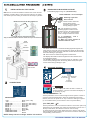
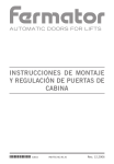
PROCEDIMIENTO DE INSTALACIÓN DEL RC11:
1
INSTALACIÓN EN LOS CABLES:
3
(4 PASOS)
TENSIÓN DE INHIBICIÓN O BLOQUEO:
Rango de la tensión de inhibición ( 24-220 V ac/dc);
NOTA: NO HAY DISTANCIA MÍNIMA ENTRE EL SENSOR Y
EL AMARRACABLES, siempre y cuando los cables estén
agarrados por la pinza y reposen paralelamente sobre los
cilindros superior e inferior.
Contacto de puertas / micro-interruptor
PIN 5
Señal de inhibición con el
contacto de puertas
PIN 6
Ambos tornillos fuertemente apretados
24- 230Vac/dc
Contacto cerrado cuando la/s puertas están
cerradas y contacto abierto cuando las puertas
comienzan a abrirse.
NOTA: Es obligatorio usar la señal de
bloqueo del equipo para evitar errores
dinámicos en la medida y corregir el peso de la
cadena de compensación.
Arandelas de apriete marcadas con el diámetro de los cables en
milímetros
Instalaciones con cadena de
compensación.
Cuando se instale indicador (acústico /
luminoso) en el interior de cabina.
CABLES
BRIDA / PINZA
Rc11
TOPE / CILINDRO
El RC11 debe recibir continuamente la señal de inhibición durante el
tiempo que dure el viaje, desde que las puertas están cerradas y comienza
el viaje hasta que llega a la planta de destino y comienzan a abrirse.
NOTA: Continuamente (Tensión 24-230Vac/dc)
NO HAY
DISTANCIA
MÍNIMA.
El display quedará bloqueado (fijo) al recibir esta señal.
VER PUNTO 1
Esto es un ejemplo para realizar la operación de inhibición coordinada
con la maniobra, pero esta operación se puede gestionar de otros
modos, depende de cada instalación y cada maniobra.
INDICADOR DE CABINA
4
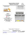
TECLADO Y SIMBOLOS:
Rc11
OUTPUTS
RL1
RL2
NA
INPUTS
Disabling
Input
1
2
C
C
24 - 230Vdc-ac
3
4
NA
Cabin
Display
9
10
5
6
7
8
_
+
24 - 48Vdc
Power supply
2
CONEXIONES:
RL1 RL2 (-)
<<
P
S
WECO
ALARMA 1
ACTIVADA
VALORES
NEGATIVOS
ALARMA 2
ACTIVADA
NOTA: EL DISPLAY PERMANECERÁ APAGADO
Después de 5 minutos de funcionamiento normal.
Presionando cualquier tecla se visualizan de nuevo los
valores del display.
TECLA DE PROGRAMACIÓN “P”
CÓDIGO DE CONEXIONADO:
+ Vdc
PIN 8 (+24 / +48)
- Vdc……............................ PIN 7 ( GND )
INHIBICIÓN........................ PIN 6 (24 - 230 Vdc/ac)
INHIBICIÓN........................ PIN 5 (24 - 230 Vdc/ac)
RELÉ 1..………….............. PIN 1 (NO)
RELÉ 1..…..…................... PIN 2 (C)
RELÉ 2…..……….............. PIN 3 (C)
RELÉ 2…....…................... PIN 4 (NO)
INDICADOR DE CABINA... PIN 9
INDICADOR DE CABINA... PIN 10
NOTA: RANGO ELÉCTRICO DE RELÉS:
250Vac/ 3 A resistencia
Esta tecla permite pasar por los menús para seleccionar los parámetros, y
una vez introducido el valor es necesario volver a pulsar “P” antes de salir
para que se guarden los daros en Eeprom (Memoria no volátil para
reservar los datos aunque se corte la alimentación.
TECLA DE SUBIR Y ESCAPE “ /S”
Esta tecla permite incrementar el valor de los menús de preselección de
datos, posee dos velocidades de incremento, de 1 en 1, y si se mantiene
pulsada, de 20 en 20.
También esta tecla permite salir de los menús sin guardar los datos en la
Eeprom. En los menús de alarmas pasa de una a otra sin pasar por sus
parámetros. En el modo pesaje si se mantiene pulsada nos permite
visualizar el peso real de la instalación sin la corrección de compensación
de cadena en los casos que la señal de bloqueo esté activada.
MANUAL TÉCNICO RC11 09-A09/2015
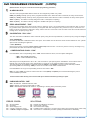
Rc11 PROCEDIMIENTO DE INSTALACIÓN:
(5 STEPS)
PRESIONANDO LA TECLA “P” DURANTE 3 SEGUNDO SE COMIENZA CON LA SECUENCIA DE PROGRAMACIÓN
1
VALORES DE LAS ALARMAS:
El RC11 tiene dos alarmas que pueden ser configuradas por ALTO = H o por BAJO = L.
ALTO = H: Relé permanece abierto hasta que el peso llega al valor programado, por encima de este valor estará cerrado.
BAJO = L: Relé permanece cerrado hasta que le peso llega al valor programado, por encima de este valor estará abierto.
ALARMA 1 (RL1): Se puede asignar a cualquier automatización, su función más común es COMPLETO 80% CARGA TOTAL
ALARMA 2 (RL2): Se asignará obligatoriamente a SOBRECARGA 100% CARGA TOTAL
2
AJUSTE DE TARA o CERO: “Tar”
Se procederá a realizar el ajuste de tara cuando la cabina esté situada en la planta más baja y totalmente vacía. “Se recomienda
saltar encima de cabina con el objeto de evitar posibles fricciones guías y cabina. Seleccionamos “YES” / SI y presionamos la tecla
“P”, el display comienza a parpadear durante 15 segundos para permitir al instalador dejar libre la cabina, y de este modo realizar
el CERO o TARA de la misma. “Cualquier peso que haya que no pertenezca a la cabina y sus accesorios a la hora de realizar
este proceso, provocará errores de peso en el funcionamiento normal del limitador de carga”.
3
CALIBRACIÓN: “DIA / LOA”
En este punto seleccionamos el procedimiento o método de calibración:
Automático, si seleccionamos “DIA”, o manual si seleccionamos “LOA”.
DIA: (DIÁMETRO DE CABLES).
Introducimos el diámetro de los cables de tracción en milímetros. Este número debe coincidir con el marcado en las arandelas de
apriete, y estas a su vez con el diámetro del cable, de lo contrario el equipo no funciona correctamente.
LOA: (PESO CONOCIDO):
Colocamos un peso dentro de cabina que debe ser al menos el 50% de la carga máxima, una vez el peso este dentro introducimos
mediante las teclas este valor en Kg. y pulsamos “P” para guardar la calibración.
4
PESO DE LA CADENA DE COMPENSACIÓN: “CHAI”
Si la instalación posee cadena de compensación, en este menú debemos introducir “YES” / SI, y en caso contrario “NO”.
IMPORTANTE: Si seleccionamos “YES”, debemos estar seguros que el equipo está recibiendo la señal de inhibición o bloqueo PIN 5 y
PIN 6 como se explica en el punto 3 del manual de instalación.
El equipo debe recibir entre 24 y 230 Vac/dc cuando las puertas están cerradas y todavía no ha iniciado el viaje, esta tensión debe
mantenerse durante todo el viaje, de lo contrario el equipo realizará operaciones de peso aleatorias dando como resultado un mal
funcionamiento, debe dejar de recibir esta tensión cuando el ascensor comienza a abrir puertas cuando llega al final del trayecto.
CONFIGURACIÓN DEL SISTEMA PARA PUERTAS ANTICIPADAS:
La configuración del sistema se complica un poco cuando el ascensor comienza el viaje antes de cerrar totalmente las puertas o comienza
a abrir las puertas antes de estar parado, para solucionarlo de forma sencilla hemos diseñado el software puertas anticipadas:
INHI: Programación de 0-11 (2 = 0.520 seg. 11 = 2.89 seg.). Usando este parámetro ajustamos la anticipación con la que el ascensor
comienza el viaje antes de cerrar puertas.
DESIN: Programación de 0-11 (2 = 520 seg. 11 = 2.89 seg.). Usando este parámetro ajustamos la anticipación con la que el ascensor abre
puertas antes de realizar la parada total.
5
INDICADOR DE CABINA: “IND”
NO:
No hay indicador de cabina en la instalación.
PROG: Tenemos instalados cualquier indicador progresivo LPM o MP de la marca WECO.
BASI: Tenemos instalados cualquier indicador acústico-luminoso PL o ML de la marca WECO.
ML model
MP model
LPM model
(Basic)
(Progressive)
(Progressive)
NOTA: Si al terminar la programación el equipo detecta algún tipo de error, consultar última página para ver cual es el
problema y la solución.
MANUAL TÉCNICO RC11 09-A09/2015
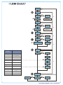
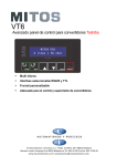
FLUJOGRAMA
000
“P”
1
RL1
“P”
“S”
R1H
R1L
“S”
“P”
“S”
Kg
Alarma 1:
COMPLETO
0/999
“P”
RL2
“P”
“S”
R2H
R2L
“P”
“S”
Kg
“S”
Alarma 2:
SOBRECARGA
0/999
“P”
2
TAR
“P”
“S”
YES
“P”
3
“S”
DIA
LOA
“P”
“S”
mm
“P”
0/999
6.0; 8.0/16.0
“P”
PARÁMETROS
INHI-DESIN
4
Delay Approx.
0
SIN PUERTAS ANTICIPADAS
1
SIN PUERTAS ANTICIPADAS
2
0.5 Seg.
3
0.8 Seg.
4
1 Seg.
5
1.3 Seg.
6
1.6 Seg.
“S”
NO
“P”
“S”
Kg
“S”
CHA
“P”
“S”
YES
NO
“P”
“P”
INH
“P”
7
1.8 Seg.
8
2 Seg.
9
2.4 Seg.
10
2.6 Seg.
11
2.9 Seg.
“S”
Unit
0 / 11
“P”
“S”
DES
“P”
“S”
Unit
0 / 11
“P”
5
“S”
BAS
“P”
IND
“P”
NO
“P”
“S”
“S”
PRO
“P”
MANUAL TÉCNICO RC11 09-A09/2015
Rc11 INSTALLATION PROCEDURE:
1
(4 STEPS)
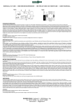
INSTALLATION ON THE ROPES:
3
DISABLING OR BLOCKING VOLTAGE:
The disabling signal range is ( 24-220 V ac/dc);
NB:There is no minimum distance between the sensor and the
shackles, providing all the ropes are held in place by the clamp
and all the ropes are resting on all three of the clamp's cylinders.
DOOR CONTACT / micro-interruptor
PIN 5
PIN 6
Both screws must be fully tightened.
Disabling signal with
Door Contact:
24- 220V
Closed contact when the
ac/dc
door(s) is/are closed
and open contact when the
door(s) start(s) to open.
NB: It is compulsory to use the
disabling signal in order to avoid
dynamic errors in the measurement
and to correct the compensating
chain´s weight in these two cases:
(1) In installations with a
compensating chain.
(2) When any cabin indicator is
installed inside the cabin.
Cylinder spacers limiting the tightness.
They are marked with the diameter of the wire ropes in millimetres.
WIRE
ROPES
CLAMP
Rc11
SENSOR
CYLINDER
No
minimum
distance
see part 1
The RC11 must receive a constant blocking signal throughout the
entire journey of the lift from the moment the doors are almost fully
closed to the moment when the cabin has reached the floor and the
doors are starting to open again.
NB: This must be a continuous signal of 24-220Vac/dc.
The display will remain frozen throughout the time that the RC11
is receiving this signal.
The disabling signal can be connected using, for example, a door
contact micro (voltage) when the door(s) is/are closed, and open
contact when door(s) start(s) to open.
CABIN
INDICATORS
4
KEYS AND FIGURES:
Rc11
OUTPUTS
RL1
RL2
NA
INPUTS
Disabling
Input
1
2
C
C
24 - 230Vdc-ac
3
4
NA
Cabin
Display
9
10
5
6
7
8
_
ALARM 1
ACTIVATED
+
24 - 48Vdc
Power supply
2
NEGATIVE
VALUES
ALARM 2
ACTIVATED
CONNECTIONS:
RL1 RL2 (-)
<<
P
S
WECO
NB: The display will switch off after 5 minutes of
normal operation. The user can switch the display on
by pressing any key.
PROGRAMMING KEY “P”
SENSOR WIRING:
+ Vdc
PIN 8 (+24 / +48)
- Vdc……............................ PIN 7
DISABLING........................ PIN 6 (24 - 220 Vdc/ac)
DISABLING........................ PIN 5 (24 - 220 Vdc/ac)
RELAY 1………….............. PIN 1 (NO)
RELAY 1…..…................... PIN 2 (C)
RELAY 2………….............. PIN 3 (C)
RELAY 2…..…................... PIN 4 (NO)
CABIN INDICATOR........... PIN 9
CABIN INDICATOR........... PIN 10
This key allows the user to scroll through the menu options in order to
enter the various lift parameters. When the parameters have been
defined, the user can press the “P” key to save the settings in eeprom
(a non-volatile memory to save data in case of a power failure).
(UP- EXIT) KEY “ /S”
This key allows the user to increase the values in each menu option. By
pressing the key repeatedly, the values are increased in units of one. If
the key is held down, the values increase in units of twenty.
In measuring mode, this button allows the user to see the real weight
being supported, without taking into account the correction made by the
compensating chain software.
NOTE: Relays electrical ratings: 250Vac/ 3 A resistive
TECHNICAL MANUAL RC11 09-A09/2015
Rc11 PROGRAMMING PROCEDURE:
(5 STEPS)
(Hold down the “P” key for 3 seconds to start the programming procedure.)
1
ALARM VALUES:
The RC11 has 2 programmable alarms which can be configured by 'HIGH' or by 'LOW':
HIGH (“H”):Relay normally open up to the programmed alarm value. When this value is reached, the relay contact closes.
LOW (“L”): Relay normally closed up to the programmed alarm value. When this value is reached, the relay contact opens.
Alarm 1 (“RL1”) : This alarm is usually assigned to FULL LOAD (80% of capacity).
Alarm 2 (“RL2”) : This alarm is always assigned to OVERLOAD (100% of capacity).
2
ZERO ADJUSTMENT: “TAR”
Perform the zero setting (Tare) with an empty cabin by selecting “YES”. It is recommended to jump inside the cabin to reduce
any possible friction (also known as 'stick-tion') in the guide rails. After having done this, press the 'P' key to confirm the zero
setting, at which point the RC11 will start to beep, and the user has 15 seconds to exit the cabin so that the controller takes the
reading with a completely empty cabin.
3
CALIBRATION: “DIA / LOA”
The user must select a calibration mode: Automatic ('DIA'), using the wire rope diameter, or, manual ('LOA'), using test weights.
“DIA” (DIAMETER):
Introduce the diameter in millimetres of the wire ropes. This number must be the same as the number marked on the cylinder
spacers that are limiting the tightness.
“ LOA” (WEIGHT):
Place a known weight, (must be at least, half the useful load) inside the cabin. Introduce by means of the keys the weight in Kg,
placed inside the cabin and make the weight setting.
4
COMPENSATING CHAIN: “CHA”
If the installation has a compensating chain, “YES” must be selected. Then, two new options will appear:
- “INH”: “PRE-DISABLING” delay.
- “DES”: “POST-DISABLING” delay.
Both delays can be adjusted from “0” to “11”, and are useful on “pre-opening doors” installations. These values refer to
internal units, not seconds. Each unit is aproximately 0.3 seconds, so the maximum delay is about 3 seconds.
The ideal values for an installation of this kind should be “INH=6” and “DES=0”, but they must be manually modified
(decreasing “INH” and increasing “DES”) if the RC11 isn’t able to take stable measurements.
If the installation has not got a compensating chain we must select “NO”.
NB: If we select “YES” we must be sure that the RC11 wires (PIN 5) and (PIN 6) are connected following the point 3
of the installation procedure.
Closed contact when door(s) is/are closed and open contact when door(s) start(s) to open.
5
CABIN INDICATOR: “IND”
“NO”: No indicator installed inside the cabin.
“PRO”: WECO progressive models (MP or LPM).
“BAS”: WECO basic indicator ML model or any flashing or buzzing alarm powered by 24Vdc.
ML model
MP model
LPM model
(Basic)
(Progressive)
(Progressive)
ERROR CODES:
SOLUTIONS:
E1 ... No saved Data.
E2 ... Overload.
E3 ... Power Supply Low.
E4 ... Negative calibration weight.
E5 ... Calibration weight too high/low.
E1 ... Repeat the calibration procedure.
E2 ... Useful Load > 999 Kg.
E3 ... Check the Power Supply.
E4 ... Possible friction ('stick-tion') / Incorrect sensor wiring (check sensor wiring colour code)
E5 ... See section 3 of calibration procedure (modify the load used for calibration).
TECHNICAL MANUAL RC11 09-A09/2015
FLOW CHART
000
“P”
1
RL1
“P”
“S”
R1H
R1L
“S”
“P”
“S”
Kg
Alarm 1:
FULL LOAD
0/999
“P”
RL2
“P”
“S”
R2H
R2L
“P”
“S”
Kg
“S”
Alarm 2:
OVERLOAD
0/999
“P”
2
TAR
“P”
“S”
YES
“P”
3
“S”
DIA
LOA
“P”
“S”
mm
“P”
6.0; 8.0/16.0
0/999
“P”
Parameters
INHI-DESIN
4
Delay Approx.
0
No pre-opening doors
1
No pre-opening doors
2
0.5 Sec.
3
0.8 Sec.
4
1 Sec.
5
1.3 Sec.
6
1.6 Sec.
“S”
NO
“P”
“S”
Kg
“S”
CHA
“P”
“S”
YES
NO
“P”
“P”
INH
“P”
7
1.8 Sec.
8
2 Sec.
9
2.4 Sec.
10
2.6 Sec.
11
2.9 Sec.
“S”
Unit
0 / 11
“P”
“S”
DES
“P”
“S”
Unit
0 / 11
“P”
5
“S”
BAS
“P”
IND
“P”
NO
“S”
“S”
PRO
“P”
“P”
TECHNICAL MANUAL RC11 09-A09/2015
CÓDIGO DE ERRORES / ERROR CODES:
ER1: Datos no guardados / No saved data.
ER2: Sobrecarga / Overload.
ER3: Alimentación baja / Power supply low.
ER4: Peso conocido en negativo / Negative calibration weight.
ER5: Peso conocido Alto o Bajo / Calibration weight too low/high.
SOLUTIONS:
ER1: Volver a calibrar / Repeat the calibration procedure.
ER2: Carga útil > 9999 KG. / Useful Load > 9999 KG.
ER3: Revisar alimentación / Check the Power Supply.
ER4: Posibles enganches, revisar instalación / Possible friction (stick-tion)/Incorrect sensor wiring (check sensor wiring colour code)
ER5: Ver proceso 3 del procedimiento de calibración. Carga útil incorrecta. / See section 3 calibration procedure (modify the load used for calibration).
SOLUCIONES COMUNES / USEFUL TIPS:
La calibración se realiza preferiblemente en la planta más baja, o en la planta donde pasa más tiempo parada, esto suele ser siempre la
planta de entrada del edificio.
The calibration should preferably be performed on the lowest floor, or alternatively on the floor on which the car spends the most time
stationary (this is usually the lobby or entrance to the building).
Antes de realizar la TARA, es conveniente salta en cabina para reducir o soltar los posibles enganches.
Before performing the zero setting, it is advisable to jump inside the car to reduce any possible friction in the guide rails.
Cuando hacemos la calibración por peso conocido, es necesario utilizar por lo menos la mitad de la capacidad del ascensor y si es
posible la capacidad total.
When calibrating with test weights, although is it recommended to use at least half the capacity weight, if possible, the full capacity
weight should be used.
Si el equipo va acumulando peso con el tiempo, es una posible indicación de que la señal de inhibición no llega correctamente al
equipo durante todo el viaje. Comprobar la tensión en AC y DC. Si estamos inhibiendo en continua, la medida que nos debe dar en alterna es
“0". Durante todo el viaje no debe haber fluctuaciones de tensión para garantizar la correcta operación.
If the controller is accummulating weight over time, then this is an indication that the disabling signal is not correct, or is not continuous
throughout the entire lift journey. This can be tested using a multi-meter connected to the disabling input whilst the car is moving. Check the
voltage range in AC and DC. If the disabling signal is DC, then there should be no AC voltage. During the entire journey there should be no
signal fluctuations.
Si el equipo presenta valores negativos, existe la posibilidad de que haya enganche de guías, o que estén cambiados los cables del
sensor, verde por amarillo o rojo por negro.
If the controller is showing negative weights, then as well as being possibly caused by friction, it could also be that the yellow and
green sensor wires are connected to the controller the wrong way around.
Es muy normal que existan imprecisiones en la medida cuando la cabina está vacía con pequeños pesos provocados por las fricciones.
Por esto al ir introduciendo peso en cabina se va aumentado la precisión.
It is quite normal to experience inaccuracies in the readings when there is little or no weight inside the car. However, as the weight inside
the car increases, so too does the accuracy. This is caused by friction in the guide rails.
El RC11 debe recibir la señal de inhibición cuando las puertas están totalmente cerradas o a punto de cerrarse.
The disabling signal should be received by the RC11 when the doors are closed, or as close to being closed as possible.
La señal de inhibición debe parar cuando las puertas comienzan a abrirse.
The disabling signal should be stopped when the doors start to open.
Parámetros INHI y DESI.
(INI)
T= Este es el tiempo que la cabina se pone en movimiento antes de recibir la señal de inhibición.
(DESI) T= Este es el tiempo en que tarda la cabina en parar desde que el equipo deja de recibir la señal hasta que parar.
T /0.2636 = Valor que se debe programar en el equipo.
Ejemplo: 1.5 seg. / 0.2636 =5.69 en este caso se debe introducir & por ser el valor más cercano.
INHI and DESI parameters.
(INI)
T=This is the time that the car is in movement before the disabling signal is received.
(DESIN) T=This is the time that the car takes to stop from the moment the disabling signal is stopped
T / 0.2636 =The value which should be entered.
C/ Cerdanya, 7 Pol.Ind La Borda,
08140 Caldes de Montbui,
Barcelona (Spain) T: +34 93 865 47 18 F: +34 93 865 40 45
WECO
WECO Elevator Products
TECHNICAL MANUAL RC11 09-A09/2015