1
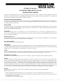
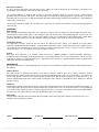
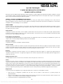
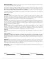
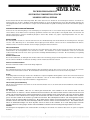
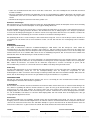
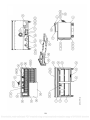
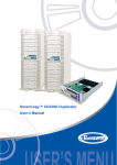
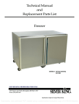
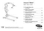
Technical Manual
and
Replacement Parts List
Refrigerated Pizza Prep Table
MODELS SKPZ60 (SHOWN)
SKPZ60D
1600 Xenium Lane North, Minneapolis, MN 55441-3787
Phone (763) 923-2441
1
Specifications Subject to Change Without Notice.
Searchable, web-optimized PDF created using a watermarked evaluation copy of CVISION Maestro
TECHNICAL MANUAL
SILVER KING PREPARATION TABLES
MODELS SKPZ60, SKPZ60D
Thank you for purchasing Silver King food service equipment. Our goal is to provide our customers with the most reliable equipment in the industry
today. Please read this manual and the accompanying warranty information before operating your new Silver King unit. Be sure to complete and
mail the warranty card within 10 days of purchase to validate your warranty.
INSPECT FOR DAMAGE AND UNCRATE
Upon delivery of your new Silver King unit, uncrate at once to inspect for possible freight damage following the instructions printed on the exterior of
the container. Report any damages to the carrier responsible for transportation and promptly present a claim for any evidence of mishandling. Save
all packaging materials if a claim is filed.
INSTALLATION
The stainless steel exterior of the cabinet has been protected by a plastic covering during manufacturing and shipping. This covering can be readily
stripped before installation. After removing this covering, wash the interior and exterior surfaces using a warm, mild soapy water solution and a
sponge or cloth, rinse with clean water and dry.
Legs/Casters
The unit comes with legs or casters. To install them, tip the unit on its back and thread the legs or casters into the four tapping plates in the base of
the unit. The casters with brakes should be installed at the front of the cabinet. Make sure that they are installed tightly to prevent future thread
wear. Periodically check for tightness.
Condenser Filter Screen
The Condenser Filter Screen, Screen Pull and Filter Guides are packaged inside the unit. The instructions for installing these parts are included in
this technical manual. Do not operate the unit without the filter screen installed!
Pans and Pan Supports
The Pans and Pan Supports are packaged with the unit.
Cutting Board
The Cutting Boards are shipped with the cabinet. The Cutting Boards have two holes in them that allign with studs installed on the top of the cabinet.
To install the Cutting Boards place the back of the boards under the lip in front of the raised rail and set them down so the studs on the cabinet top
allign with the holes in the Cutting Boards. The Cutting Boards are reversible to extend wear.
Shelves
Inside the unit you will find Shelves and a plastic bag containing Shelf Supports. The Shelf Supports hook into the Pilasters that are mounted in the
cabinet. The Shelf Supports with the tang go on the rear Pilasters. This shelf system allows for easy adjustment to suit your needs.
Door Adjustment and Swing
Should the Door ever require straightening, loosen the Screws on the Hinges, square the Door with the cabinet and retighten the Screws.
Drawers
To remove the drawers for cleaning, simply open them fully, lift up on the front of the drawer to remove the front wheels from the drawer tracks,
continue to slide the drawer out until the rear wheels reach the end of the tracks and lift the drawer out of the tracks. To reinstall the drawer, insert
the rear wheels of the drawer into the drawer tracks and slide the drawer back until the front wheels on the drawer can be inserted into the track,
push the drawer into the cabinet. . The drawer pans can be removed by lifting them out with the drawer extended. The drawer tracks can be
removed for cleaning when the drawers are removed from the cabinet. With the track fully in the cabinet, simply lift up on the drawer track to remove
it from the cabinet. The drawer slide system is rated for a maximum load of 200 pounds. The drawers are not designed for or intended to be used
as a surface to stand on. At no time should the drawers be extended and used as a platform for standing on to reach elevated equipment.
Location
When locating your new refrigerator, convenience and accessibility are important considerations, but the following installation
guidelines must be followed:
• Always avoid placing the refrigerator adjacent to an oven, heating element or hot air source that would affect the operation of the unit.
• For proper ventilation the bottom front of the unit must not be obstructed. The unit must be on legs or casters to raise it off the floor. The unit can
be installed tight on the sides and back.
• The unit must be level or tilted backwards slightly.
1
Searchable, web-optimized PDF created using a watermarked evaluation copy of CVISION Maestro
Electrical Connections
Be sure to check the data plate, located on the liner of the cabinet, for required voltage prior to connecting the unit to power. The
specifications on the data plate supersede any future discussion.
The standard refrigerator is equipped with an eight (8) foot power cord that requires a 115 Volt, 60 Cycle, 1 Phase properly
grounded electrical receptacle. The power cord comes with a 3 prong plug for grounding purposes. Any attempt to cut off the
grounding spike or to connect to an ungrounded adapter plug will void the warranty, terminate the manufacturers responsibility and
could result in serious injury.
The circuit must be protected with a 15 or 20 ampere fuse or breaker. The unit must be isolated on a circuit and not plugged into an
extension cord.
OPERATION
Initial start up
After satisfying the installation requirements, the refrigerator is ready to start. The Compressor will start when the power cord is
connected to the required power source. If the Compressor does not start when the unit is initially plugged in, check to make sure
that the Temperature Control is not in the off position. Allow the unit to run for two hours before loading it with product. When
loading the unit with product, take care not to block the air flow in the cabinet as this would affect the units performance.
Temperature Control
The Temperature Control is located on the back wall of the cabinet liner and is factory set to maintain an average cabinet
temperature of approximately 36 to 40 Deg F.. To obtain colder temperatures turn the Temperature Control stem clockwise and vice
versa. Allow the unit a minimum of one hour to respond to a control setting adjustment. To save energy, the rail cover should be
closed when rail access is not required for a period of 10 minutes or more.
Defrost
Your Silver King refrigerator is an automatic defrost unit and no additional plumbing is required. Automatic defrosting is
accomplished when frost buildup on the Evaporator Coil is cleared during Compressor off cycles. Defrost water is collected in a pan
located in the compressor compartment where it is evaporated into the room air. It is important that the unit be installed level to
allow proper drainage of the defrost water.
MAINTENANCE
Preventative maintenance is minimal although these few steps are very important to continued operation and maximizing the life of
the appliance.
Cabinet Surfaces
The cabinet interior is aluminum and stainless steel and the exterior is stainless steel. These surfaces should be cleaned
periodically with a solution of warm water and mild soap, rinsed and wiped dry with a soft cloth. A good stainless steel cleaner can
also be used. Should a surface become stained, do not attempt to clean with an abrasive cleanser or scouring pad. Use a soft
cleanser and rub with the grain of the metal to avoid scratching the surface. Do not use chlorinated cleaners. Always rinse well and
dry after cleaning.
Condenser
Periodically the Condenser Filter Screen must be cleaned. The Condenser Filter Screen is located on the bottom of the cabinet. To
clean it simply pull it out the front of the unit using the Filter Screen Pull and rinse it in a stream of water. Dry the screen by tapping it
on a counter or floor. Replace the filter screen by placing it into the filter screen tracks on the bottom of the unit and sliding it all the
way to the rear of the cabinet. Do not operate the unit without the filter sreen installed!
Door Gasket
The Door Gasket will collect dirt and should be wiped clean with a warm, mild soapy water solution to extend its life and assure
maximum cabinet performance and life.
MODEL
SERIAL NO.
DATE INSTALLED
2
Searchable, web-optimized PDF created using a watermarked evaluation copy of CVISION Maestro
FILTER GUIDES AND SCREEN INSTALLATION INSTRUCTIONS
MODELS: SKF48, SKP72I 8, SKP7230, SKPZ6O, SKPZ92, SKR48, 5KP488, SKP48I 2, SKP48I 8
DO NOT OPERATE UNIT WITHOUT FILTER SCREEN AND AIR CURTAIN INSTALLED
Disconnect unit from power source.
Tip the unit on its back and loosen the 2 screws along the top edge of the base.
Insert tab on the end of the filter guide with curtain into the slot located along the lower edge of
the base unit
Slip the opposite end of the filter guide with curtain under the screw head loosened in step 2,
pull forward, and lighten screw to secure the filter guide to base.
Repeat step 4 with right filter guide.
Insert filter screen into tracks formed by the guides and slide back until the screen stops.
Install legs or casters.
Return unit to original upright position.
This kit includes:
- Filter guide with curtain
- Right filter guide
- Filter screen
STEP 4
STEP 6
RI GIlT HAND
FILTER GUIDE
EH_L:
STEP 5
FILTER GUIDE
Vv1THCURTPJN
TAB
STEP 3
2541g
REV G
3
Searchable, web-optimized PDF created using a watermarked evaluation copy of CVISION Maestro
MANUAL TÉCNICO
MESAS DE PREPARACIÓN SILVER KING
MODELOS SKPZ60, SKPZ60D
Gracias por comprar un equipo de servicio para alimentos Silver King. Nuestro objetivo es proporcionar a nuestros clientes el equipo más confiable
en la industria actual. Sírvase leer este manual y la información sobre garantía que se adjunta antes de operar su nueva unidad Silver King.
Asegúrese de completar y enviar la tarjeta de garantía en los 10 días siguientes a la compra a fin de validar su garantía.
INSPECCIONE SI EXISTEN DAÑOS Y RETIRE LA UNIDAD DE LA CAJA DE EMBALAJE
Una vez que le ha sido entregada su nueva unidad Silver King, retírela de la caja de embalaje para verificar posibles daños por flete siguiendo las
instrucciones impresas en el exterior del contenedor. Informe sobre cualquier daño al transportista responsable y presente inmediamente un
reclamo por cualquier evidencia de mala manipulación. Si se presenta una denuncia, guarde todos los materiales de embalaje.
INSTALACIÓN
El exterior de acero inoxidable del gabinete ha sido protegido con una cubierta de plástico durante la fabricación y envío. Esta cubierta puede ser
retirada fácilmente antes de la instalación. Luego de retirar esta cubierta, lave las superficies del interior y exterior usando una solución de agua
tibia con jabón suave y una esponja o tela; enjuague con agua limpia y seca.
Patas/Ruedecillas
La unidad está equipada con Patas o Ruedecillas. Para instalarlas, incline la unidad sobre su parte posterior y enrosque las Patas o Ruedecillas en
las cuatro placas de roscado en la base de la unidad. Las ruedecillas con frenos deben ser instaladas al frente del gabinete. Asegúrese que sean
instaladas de manera firme para evitar un futuro desgaste de la rosca. Revise el ajuste de manera periódica.
Rejilla de Filtro del Condensador
La Rejilla de Filtro del Condensador, la Agarradera de la Rejilla y las Guías de Filtro están embaladas dentro de la unidad. Las instrucciones para la
instalación de estas partes están incluidas en este manual técnico. ¡No opere la unidad sin la rejilla de filtro instalada!
Parrillas y Soportes de Parrilla
Las Parrillas y Soportes de Parrilla están embaladas con la unidad.
Tabla de Picado
Las Tablas de Picado están embaladas con el gabinete. Las Tablas de Picado tienen dos agujeros que se alinean con los pernos instalados en la
parte superior del gabinete. Para instalar las Tablas de Picado, coloque la parte posterior de las tablas debajo del borde frente al riel elevado y
fíjelas hacia abajo de manera que los pernos en el gabinete se alineen con los agujeros en las Tablas de Picado. Las Tablas de Picado son
reversibles para prolongar su uso.
Estantes
Dentro de la unidad encontrará Estantes y una bolsa plástica que contiene Soportes para Estante. Los Soportes para Estante se enganchan en los
Pilares que están montadas en el gabinete. Los Soportes para Estante con rabo van en los Pilares posteriores. Este sistema de estante permite un
fácil ajuste para adaptarse a sus necesidades.
Ajuste de Puerta y Vaivén
En caso que la Puerta necesite refuerzo, afloje los Tornillos en las Bisagras, cuadre la Puerta con el Gabinete y vuelva a ajustar los Tornillos.
Cajones
Para retirar los Cajones para su limpieza, simplemente ábralos por completo, levante la parte delantera del cajón para retirar las ruedas delanteras
de las vías del cajón, continúe deslizando el cajón fuera hasta que las ruedas posteriores lleguen al final de las vías y levante el cajón fuera de las
vías. Para volver a instalar el Cajón, inserte las ruedas posteriores del cajón dentro de las vías del cajón y deslice el cajón de vuelta hasta que las
ruedas anteriores del cajón puedan ser insertados dentro de la vía, empuje el cajón hacia dentro del gabinete. Las parrillas del cajón pueden ser
retiradas levantándolas fuera del cajón extendido.
Las vías del cajón deben ser retiradas para su limpieza cuando los cajones sean retirados del gabinete. Con la vía totalmente dentro del gabinete,
simplemente levante la vía del cajón para retirarlo del gabinete.
El sistema de corredera del cajón tiene capacidad para una carga máxima de 200 libras. Los cajones no están diseñados ni tienen como propósito
servir como superficie sobre la cual pararse. Los cajones nunca deben estar extendidos y ser usados como plataforma para pararse sobre ellos a
fin de alcanzar equipos que se encuentren en una altura elevada.
Ubicación
Al ubicar su nueva refrigeradora, debe tomar en consideración la comodidad y accesibilidad. Además, debe seguir las siguientes
pautas de instalación:
4
Searchable, web-optimized PDF created using a watermarked evaluation copy of CVISION Maestro
• Siempre evite ubicar la refrigeradora cerca a un horno, elemento de calor o fuente de aire caliente que pudiera afectar la
operación de la unidad.
• Para una adecuada ventilación, la cara inferior de la unidad no debe ser obstruida. La unidad debe encontrarse sobre patas o
ruedecillas para elevarla del piso. La unidad puede ser instalada fija en los lados y en la parte posterior.
• La unidad debe estar nivelada o inclinada ligeramente hacia atrás.
Conexiones Eléctricas
Asegúrese de revisar la placa de información, ubicada en el revestimiento del gabinete, para conocer el voltaje requerido, antes de
conectar la unidad a la corriente. Las especificaciones en la placa de información invalidan cualquier discusión futura.
La refrigeradora estándar está equipada con un cable de corriente de (8) pies que requiere un tomacorriente monofásico de 115
Voltios, 60 Ciclos, debidamente puesto a tierra. El cable de corriente tiene un enchufe de 3 espigas para la puesta a tierra.
Cualquier intento de cortar la espiga de puesta de tierra o de conectar a un enchufe adaptador no puesto a tierra invalidará la
garantía, pondrá fin a la responsabilidad de los fabricantes y podría traer como resultado graves lesiones.
El circuito debe estar protegido con un fusible o cortacircuito de 15 o 20 amperios. La unidad debe ser aislada en un circuito y no
debe ser conectada a un cable de extensión.
OPERACIÓN
Arranque inicial
Luego de haber cumplido con los requisitos de instalación, la refrigeradora está lista para arrancar. La Compresora arrancará
cuando el cable de corriente se encuentre conectado a la fuente de poder requerida. Si la Compresora no arranca cuando la
unidad es inicialmente enchufada, revise y asegúrese que el Control de Temperatura no se encuentra en posición de apagado.
Deje que la unidad funcione durante dos horas antes de cargarla con producto. Cuando cargue la unidad con producto, tenga
cuidado de no bloquear el flujo de aire en el gabinete pues esto afectará el rendimiento de la unidad.
Control de Temperatura
El Control de Temperatura se encuentra ubicado en la pared posterior del revestimiento del gabinete y es fijado en fábrica para
mantener una temperatura promedio dentro del gabinete de aproximadamente 36 a 40 grados F. Para obtener temperaturas más
frías, gire el botón de Control de Temperatura en sentido horario y viceversa. Deje la unidad como mínimo durante una hora para
responder a un ajuste de configuración de control. Para ahorrar energía, la cubierta del riel debe estar cerrada cuando no es
necesario tener acceso al riel durante un período de 10 minutos o más.
Descongelamiento
Su refrigeradora Silver King es una unidad de descongelamiento automático y no es necesario tuberías adicionales. El
descongelamiento automático termina cuando la acumulación de escarcha en la Bobina del Evaporador es eliminada durante los
ciclos de apagado de la Compresora. El agua de la escarcha es recogida en una parrilla ubicada en un compartimento de la
compresora donde es evaporada hacia el aire de la habitación. Es importante que la unidad sea instalada de manera horizontal
para permitir un adecuado drenado del agua de descongelamiento.
MANTENIMIENTO
El mantenimiento preventivo es mínimo; sin embargo, estos pasos son muy importantes para una operación continua y para
maximizar la vida del artefacto.
Superficies del Gabinete
El interior del gabinete es de aluminio y de acero inoxidable y el exterior, de acero inoxidable. Estas superficies deben ser
limpiadas periódicamente con una solución de agua tibia y jabón suave, enjuagadas y secadas con una tela suave. También puede
emplearse un buen limpiador de acero inoxidable. En caso de que una superficie se haya teñido, no intente limpiarla con un
limpiador abrasivo o esponja para frotado. Use un limpiador suave y frote con el granulo del metal para evitar arañar la superficie.
No use limpiadores con cloro. Siempre enjuague bien y seque después de la limpieza.
Condensador
La Rejilla de Filtro del Condensador debe ser limpiada periódicamente. La Rejilla de Filtro del Condensador se encuentra ubicada
en la parte inferior del gabinete. Para limpiarla, simplemente jálela fuera del frente de la unidad usando la Agarradera de la Rejilla
de Filtro, y enjuáguela en agua. Seque la rejilla drenándola en un mostrador o en el piso. Reemplace la rejilla de filtro colocándola
en la vía de la rejilla de filtro ubicada en la parte inferior de la unidad y deslizándola todo el camino hacia la parte posterior del
gabinete. ¡No opere la unidad sin haber instalado la rejilla de filtro!
Junta de la Puerta
La Junta de la Puerta recoge la suciedad y debe ser limpiada con una solución de agua con jabón suave y tibia para prolongar su
vida y asegurar un máximo rendimiento y vida del gabinete.
MODELO
SERIE NO.
FECHA DE INSTALACIÓN
5
Searchable, web-optimized PDF created using a watermarked evaluation copy of CVISION Maestro
MANUEL TECHNIQUE
TABLES DE PREPARATION SILVER KING
MODELES SKPZ60, SKPZ60D
Merci d’avoir choisi un équipement Silver King. Notre objectif est d’offrir à nos clients l’équipement le plus fiable de l’industrie. Veuillez lire ce manuel
et les informations relatives à la garantie avant d’utiliser votre nouvelle unité Silver King. Assurez-vous de remplir et de renvoyer la carte de garantie
dans les 10 jours suivant votre achat pour valider votre garantie.
VERIFIEZ L’ABSENCE DE DOMMAGES ET DE DEFAUTS
Dès réception de votre nouveau Silver King, veuillez l’examiner et le tester pour vérifier l’absence de dommages. Pour ce faire, suivez les
instructions imprimées sur la face externe du conteneur. Signalez les dommages au transporteur et présentez une réclamation en cas de mauvaise
manipulation. Conservez l’emballage en cas de réclamation.
INSTALLATION
La surface externe en acier inox de l’armoire a été protégée à l’aide d’un revêtement en plastique durant la fabrication et pendant le transport.
Retirez ce revêtement avant l’installation. Ensuite, nettoyez les surfaces interne et externe à l’aide d’eau savonneuse chaude et d’une éponge ou
d’un chiffon doux, rincez et séchez.
Pieds/roulettes
L’unité dispose de pieds ou de roulettes. Pour les installer, retournez l’unité et vissez les pieds ou les roulettes dans les quatre plaques taraudées
de la base de l’unité. Installez les roulettes avec frein à l’avant de l’armoire. Assurez-vous que vous les avez installées fermement afin d’éviter
l’usure des filets. Vérifiez régulièrement le serrage.
Ecran du filtre du condensateur
L’écran du filtre du condensateur, la poignée et les guides du filtres sont emballés dans l’unité. Les instructions pour l’installation de ces pièces sont
comprises dans ce manuel technique. N’utilisez pas l’unité sans l’écran du filtre !
Plateaux et supports
Les plateaux et les supports sont emballés à l’intérieur de l’unité.
Plan de découpe
Les plans de découpe sont livrés avec l’armoire. Les plans de découpe disposent de deux orifices qui s’alignent sur les pitons installés en haut de
l’armoire. Pour installer les plans de découpe, placez le dos des plans sous la lèvre en face du rail relevé et abaissez-les de sorte que les orifices
des plans et les pitons coïncident. Les plans peuvent être retournés afin d’allonger leur durée de service.
Etagères
Vous trouverez à l’intérieur de l’unité des étagères et un sac en plastique qui contient leurs supports. Les supports pour étagère doivent être
suspendus à la pilastre de l’armoire. Les supports pour étagère à tenon sont fixés aux pilastres arrière. Cette étagère permet un réglage facile en
fonction de vos besoins.
Réglage de la porte et jeu
Si la porte doit être redressée, desserrez les vis de charnières, redressez la porte et le resserrez les vis.
Tiroirs
Pour nettoyer les tiroirs, ouvrez-les complètement, relevez la partie avant du tiroir pour extraire les roulettes avant du rail et tirez sur le tiroir jusqu’à
extraire les roulettes arrière du rail. Pour replacer le tiroir, introduisez les roulettes arrière du tiroir dans les rails et faites glisser le tiroir vers l’arrière
jusqu’à ce que les roulettes avant s’alignent dans les rails. Poussez ensuite le tiroir dans l’armoire. Vous pouvez retirer les panneaux du tiroir en les
soulevant lorsque le tiroir est tiré. Vous pouvez retirer les rails du tiroir pour les nettoyer lorsque les tiroirs ont été séparés de l’armoire. Il vous suffit
de soulever les rails pour les séparer de l’armoire. Le système coulissant du tiroir supporte une charge maxi de 200 livres. Les tiroirs ne sont pas
prévus pour supporter le poids d’une personne. N’utilisez jamais les tiroirs en tant qu’escalier pour atteindre un équipement situé en hauteur.
Emplacement
Lorsque vous placez votre réfrigérateur, tenez compte de la facilité d’accès et suivez les recommandations suivantes :
•
•
•
Evitez de placer le réfrigérateur à proximité d’un four, d’une source de chaleur ou d’air chaud car ce pourrait provoquer des
dysfonctionnements.
Pour une correcte ventilation, la face inférieure avant de l’unité ne doit pas être obstruée. Pour séparer l’unité du sol, utilisez des pieds ou des
roulettes. Les faces latérales et arrière peuvent être appuyées contre le mur.
L’unité doit être de niveau ou légèrement inclinée vers l’arrière.
6
Searchable, web-optimized PDF created using a watermarked evaluation copy of CVISION Maestro
Branchements électriques
Vérifiez la tension indiquée sur la plaque de caractéristiques, placée sur le plan de l’armoire, avant de brancher l’unité au secteur.
Les caractéristiques de la plaque sont les seules valables.
L’unité standard est équipée d’un cordon d’alimentation de huit (8) pieds de long pour 115 volts, 60 Hz, monophasé et correctement
mis à la masse. Le cordon dispose d’une fiche à trois broches pour la mise à la masse. Si vous coupez la broche de mise à la
masse ou que vous utilisez la fiche avec une prise sans neutre, la garantie perd sa validité. Ce pourrait entraîner de graves
blessures. En outre, le fabricant décline toute responsabilité en cas de dommage.
Le circuit doit être protégé à l’aide d’un fusible de 15 ou 20 ampères ou d’un rupteur. L’unité doit être isolée sur un circuit. Ne la
branchez pas sur une allonge.
UTILISATION
Première utilisation
Une fois son installation correcte terminée, l’unité est prête. Le compresseur démarre lorsque vous branchez le cordon
d’alimentation à une source de courant. Si le compresseur ne démarre pas lors du branchement de l’unité, vérifiez que le
thermostat n’est pas désactivé. Laissez fonctionner l’unité durant deux heures avant de la charger. Lorsque vous chargez l’unité,
n’obstruez pas la circulation de l’air dans l’armoire car ce pourrait entraîner des dysfonctionnements.
Thermostat
Le thermostat est placé sur la face arrière du plan de l’armoire. Il est réglé d’origine pour maintenir la température de l’armoire entre
36 et 40 º F. Pour réduire la température, faites tourner le thermostat dans le sens des aiguilles d’une montre. Patientez au moins
une heure pour constater le changement de réglage. Pour économiser l’énergie, le couvercle du rail doit être fermé lorsque vous ne
devez pas y accéder dans les 10 minutes suivantes.
Dégivrage
Votre unité Silver King est une unité à dégivrage automatique et aucune connexion supplémentaire n'est nécessaire. Le dégivrage
automatique se fait lorsque l’accumulation de givre sur la bobine de l’évaporateur est éliminé lors des cycles d’arrêt du
compresseur. L’eau du dégivrage est recueillie dans un plateau situé dans le compartiment du compresseur. Elle s’évapore dans
l’air de la pièce. L'unité doit être de niveau afin que les condensats puissent être purgés correctement.
ENTRETIEN
L’entretien préventif est minime mais il est essentiel pour permettre le bon fonctionnement et la longue durée de service de
l’appareil.
Surfaces de l’armoire
La partie interne de l’armoire est en aluminium et en acier inox et la partie extérieure est en acier. Nettoyez ces surfaces
régulièrement à l’aide d’une solution d’eau chaude et de détergent doux, rincez et séchez à l’aide d’un chiffon. Vous pouvez
également utiliser des éponges en acier inox. Si les surfaces s’oxydent, n’utilisez pas de produits abrasifs ou agressifs. Utilisez un
chiffon doux et frottez dans le sens du grain afin de ne pas griffer la surface. N’utilisez pas d’eau de javel. Rincez et séchez après le
nettoyage.
Condensateur
Nettoyez correctement l’écran du filtre du condensateur. L’écran du filtre du condensateur est placé en bas de l’armoire. Pour le
nettoyer, tirez la partie avant de l’unité à l’aide de la poignée de l’écran du filtre et rincez-le à l’eau claire. Séchez l’écran et le
tapotant sur le sol. Replacez l’écran du filtre en le remettant dans les rails de l’écran du filtre en bas de l’unité et faites-le glisser
jusqu’au fond de l’armoire. N’utilisez pas l’unité sans l’écran du filtre !
Joint de la porte
Le joint de la porte recueille les poussières. Nettoyez-le avec une solution d’eau chaude et de détergent doux pour assurer la durée
de service de l’armoire.
MODELE
Nº DE SERIE
DATE INSTALLATION
7
Searchable, web-optimized PDF created using a watermarked evaluation copy of CVISION Maestro
TECHNISCHES HANDBUCH
SILVER KING ZUBEREITUNGSTISCHE
MODELLE SKPZ60, SKPZ60D
Recht herzlichen Dank für Ihren Silver King Ankauf. Wir streben danach unseren Kunden mit den zuverlässigsten Geräten in der Industrie zu
bedienen. Bitte lesen Sie dieses Handbuch und die Garantieunterlagen vor Sie mit der Bedienung Ihrer neuen Silver King Anlage anfangen. Der
hinzugefügte Garantieschein soll innerhalb von 10 Tagen nach dem Ankaufsdatum ausgefüllt und zurückgeschikt werden um die Garantie gültig zu
machen.
AUSPACKEN UND AUF BESCHÄDIGUNGEN
Packen Sie Ihre neue Silver King Anlage sofort nach Empfang aus und inspizieren Sie sie auf eventuelle Transportschaden. Bitte achten Sie dabei
auf die Hinweise auf der Außenseite der Verpackung. Irgendwelche Schaden sollen dem Spediteur sofort mitgeteilt werden, und zusammen mit
jeglichen Beweisstücken schlechter Handhabung übergeben werden. Bitte behalten Sie jegliche Verpackungsmaterialien falls Sie einen
Schadenersatzanspruch erheben.
INSTALLATION
Das Schrankgehäuse besteht aus rostfreiem Stahl und ist mit einer Plastikabdeckung zum Schutz während der Herstellung und des Transports
versehen. Diese Abdeckung soll vor der Installation einfach abgezogen werden. Danach sollen Sie die Innen- und Außenflächen mit warmem,
mildem Seifenwasser und einem Schwamm oder Tuch reinigen, gut abspülen und trockenwischen.
Füße/Schwenkrollen
Das Gerät ist mit Füßen oder Schwenkrollen versehen die noch montiert werden sollen. Heben Sie den Tisch auf und schieben Sie die Füße oder
Schwenkrollen in die 4 Innengewinden in der Unterseite des Geräts. Die mit Bremsen versehenen Schwenkrollen sollen vorne am Schrank
montiert werden. Bitte stellen Sie sicher, daß sie gut festsitzen um künftige Gewindeabnutzung zu vermeiden.. Die Verschraubung soll regelmäßig
geprüft werden.
Kondensatorfiltersieb
Das Kondensatorfiltersieb, der Siebzugriff und der Filterschlitten sind in der Anlage gelagert. Die Montagehinweise für diese Teile finden Sie in
diesem technischen Handbuch. Vor Gebrauch der Anlage sollen Sie zunächst das Filtersieb montieren!
Pfannen und Pfannenstützen
Die Pfannen und Pfannenstützen werden mit der Anlage mitgeliefert.
Schneidebrett
Die Schneidebretter werden mit dem Schrank mitgeliefert. Die Schneidebrette sind mit zwei Löchern versehen die sich mit den oben auf dem
Schrank versehenen Ansätzen ausrichten. Die Schneidebretter sind zweiseitig verwendbar um eine hohe Lebensdauer zu gewähren.
Regale
In der Anlage finden Sie die Regale und die in einer Plastiktasche verpackten Regalhälter. Die Regalhälter sollen in die in dem Schrank montierten
Halbpfeiler eingehakt werden. Die Regalhälter mit dem Mitnehmer sollen auf die hintere Halbpfeiler montiert werden. Dieses Regalsystem
ermöglicht eine einfache Anpassung um Ihre Bedürfnisse entgegenzukommen.
Türverstellung und Schwenkung
Falls die Tür je verstellt werden soll, brauchen Sie nur die Schenkelschrauben zu lösen, die Tür mit dem Schrank einzuwinkeln, und die Schrauben
wieder festzusetzen.
Schränke
Zur Reinigung der Schränke, sollen Sie sie einfach ganz herausziehen, vorne aufheben um die vorderen Räder von dem
Schrankschienen zu entfernen, und den Schrank weiter herausziehen bis die hinteren Räder auf dem Schienenende ruhen und
einfach von den Schrankschienen entfernt werden können. Um die Schränke wieder einzuschieben, sollen Sie die hinteren Räder
des Schrankes in die Schrankschienen einlegen und den Schrank nach hinten schieben bis die vordere Räder in den Schienen
passen und den Schrank in das Gehäuse geschoben werden kann. Die Schrankpfannen können auch herausgehoben werden,
aber nur wenn der Schrank völlig ausgezogen ist. Die Schrankschienen können auch herausgehoben werden aber nur wenn die
Schränke entfernt sind. Heben Sie die ineinandergeschobenen Schienen einfach aus dem Schrank heraus. Die Schrankschienen
haben ein Höchstladevermögen von 90,72 Kg. Bitte stehen Sie nicht auf die Schränke da sie nicht dafür geeignet sind. Die
Schränke dürfen nie herausgezogen werden und als Standfläche benutzt werden um hochliegende Gegenstände zu erreichen.
Standort
Zweckmäßigkeit und Zugänglichkeit sind selbstverständlich sehr wichtig bei der Auswahl eines Standorts. Bitte achten Sie jedoch auf folgende
Richtlinien:
8
Searchable, web-optimized PDF created using a watermarked evaluation copy of CVISION Maestro
• Stellen Sie den Kühlschrank niemals neben einem Ofen, Heizelement oder einer Heizluftquelle die den Betrieb der Einheit
beeinflussen würden.
• Die untere Vorderfläche der Einheit soll einwandfrei sein um eine gute Belüftung zu gewähren. Die Einheit soll auf Füßen oder
Schwenkrollen stehen um sie von den Boden zu heben. Die Seitenflächen und Rückfläche dürfen jedoch eng eingeschoben
werden.
• Die Einheit soll waagerecht oder leicht nach hinten gehoben sein.
Elektrische Verbindungen
Bitte überprüfen Sie vor der Inbetriebstellung der Anlage das Spannungbedürfnis anhand der Datenplatte auf der Innenverkleidung
des Schrankes. Die Daten auf der Datenplatte ersetzen jegliche künftige Diskussion.
Der Standardkühltisch ist mit einer acht (8) Fuß (= 2,438 m) langen Anschlußschnur versehen. Diese Schnur arbeitet mit einer 115
Volt, 60 Perioden, einphasig laufenden Steckdose. Die Anschlußschnur hat ein Erdungsstöpsel mit 3 Zweigen. Irgendwelche
Versuche um die Erdungsspannungsspitze zu entfernen oder mit einem ungeerdeten Zwischenstecker zu verbinden, vernichten die
Garantie, beenden die Verantwortung des Herstellers und kann zu ernsthaften Verletzungen führen.
Die Schaltung soll mit einer 15 oder 20 Ampere starken Schmelzsicherung, bzw. einem 15 oder 20 Ampere starken Unterbrecher
ausgestattet sein. Die Einheit soll auf einem Stromkreis isoliert sein und darf nicht mit einer Verlängerungsschnur verbunden
werden.
BEDIENUNG
Erstmalige Inbetriebsetzung
Das Gerät ist arbeitsbereit sobald die Installationsbedingungen erfüllt worden sind. Der Kompressor startet sobald die
Anschlußschnur in die vorgeschriebene Steckdose eingeschaltet ist. Falls der Kompressor nicht startet wenn die Anlage zum
ersten Mal eingeschaltet wird, sollen Sie überprüfen ob die Temperaturkontrolle nicht ausgeschaltet ist. Lassen Sie die Anlage zwei
Stunden laufen bevor Sie sie auffüllen. Bitte achten Sie bei der Produktlagerung darauf, daß der Lufstrom in dem Schrank nicht
blockiert wird da dies die Arbeitsleistung des Geräts beeinflussen würde.
Temperaturkontrolle
Die Temperaturkontrolle befindet sich auf der Hinterfläche der Schrankverkleidung und ist auf ungefähr 2,222 bis 4,444 Grad
Celsius werkseingestellt. Schieben Sie die Temperaturröhre im Uhrzeigersinn um die Temperatur herabzusenken und umgekehrt.
Bitte erlauben Sie mindestens eine Stunde um die erwünschte Temperatur zu erreichen. Um Energie zu sparen, soll die
Schienenabdeckung verschlossen sein wenn die Schienen 10 Minuten oder länger nicht gebraucht werden.
Entfrostung
Ihr Silver King Kühlschrank ist mit einer automatischen Entfrostungsanlage versehen und bedarf keine zusätzliche Rohre. Die
automatische Entfrostung entfernt Eis von der Verdampferschlange wenn der Kompressor ausgeschaltet ist. Das
Entfrostungwasser wird in einer Pfanne in dem Kompressorabteil gesammelt und dann in die Raumluft verdampft. Bitte achten Sie
darauf, daß das Gerät waagerecht steht um eine gute Entwässerung des Kondenzwassers zu gewähren.
WARTUNG/PFLEGE
Obschon die vorbeugende Wartungsarbeiten minimal sind, sind sie sehr wichtig für einen ununterbrochenen Betrieb und eine
höchstmögliche Lebensdauer Ihres Gerätes zu gewähren.
Schrankflächen
Die Innenfläche des Schrankes besteht aus Aluminium und rostfreiem Stahl, und die Außenseite aus rostfreiem Stahl. Reinigen Sie
diese Flächen regelmäßig mit warmem, mildem Seifenwasser, spülen Sie alles gut ab mit klarem Wasser und wischen Sie das
Gerät trocken mit einem Tuch. Reiniger für rostfreier Stahl sind auch geeignet. Bitte verwenden Sie keine scheuernde
Reinigungsmittel oder Padschwämme um Verschmutzungen zu entfernen. Verwenden Sie ein mildes Reinigungsmittel und reiben
Sie mit der Metallfaser um Kratzer zu vermeiden. Chlorreinigungsmittel sind nicht erlaubt. Nach der Reinigung muss alles gut
nachgespült und abgetrocknet werden.
Kondensator
Das Kondensatorfiltersieb soll regelmäßig entstaubt werden. Das Kondensatorfiltersieb befindet sich unten am Schrank. Zur
Reinigung sollen Sie einfach am Filtersiebgriff ziehen, das Filtersieb entfernen und mit laufendem Wasser abspülen. Zum trocknen
sollen Sie das Sieb leicht auf der Theke oder dem Boden abklopfen. Legen Sie das Filtersieb auf die Filtersiebschienen unten am
Gerät ein und schieben Sie es ganz bis hinten im Schrank. Das Gerät darf nicht ohne Filtersieb benutzt werden!
MODELL
SERIEN-NR.
INSTALLATIONSDATUM
9
Searchable, web-optimized PDF created using a watermarked evaluation copy of CVISION Maestro
0
o
iwF
o
00
0O
10
Searchable, web-optimized PDF created using a watermarked evaluation copy of CVISION Maestro
REPLACEMENT PARTS LIST - SKPZ6O/D
ITEM NO.
1
2
3
4
5
6
8
9
10
11
12
13
14
15
16
17
18
19
20
21
22
23
24
2S
26
27
28
29
30
31
32
33
34
3S
36
37
38
39
PART DESCRIPTION
PART NO.
DOOR ASSEMBLY
DOOR LINER
DOOR GASKET
TEMPERATURE CONTROL PLATE
TEMPERATURE CONTROL
BACK PANEL
MOTOR FAN 115V
MOTOR FAN 220V
FAN BLADE
SHELF (LOWER)
SHELF (UPPER)
HINGE (UPPER)
HINGE (LOWER)
HANDLE COVER
DOOR BUSHING
DOOR WASHER
CONDENSER COIL
FAN MOTOR 115V
FAN MOTOR 230V
FAN BLADE
COMPRESSOR 115V (WITH DRIER & ELECTRICALS)
COMPRESSOR 230V (WITH DRIER & ELECTRICALS)
COMPRESSOR ELEC 115V (OVERLOAD, RELAY, ETC)
COMPRESSOR ELEC 230V (OVERLOAD, RELAY, ETC)
POWER CORD 115V
POWER CORD 230V
CONDENSATE PAN ASSEMBLY 11 SV
CONDENSATE PAN ASSEMBLY 230V
GROMMET - COMPRESSOR MOUNT
HAIRPIN CLIP
WASHER - COMPRESSOR MOUNT
DRIER
TEMPERATURE INDICATOR
RAIL COVER
24554
10309-10
10310-34
20653
20889
26478
SHELFSUPPORTWITHTANG
SHELFSUPPORTWITHOUTTANG
SHELFPILASTER16IN
SHELF PILASTER 8.S IN
FILTER SCREEN
KIT PLATE CASTERS
EVAPORATOR WITH HEAT EXCHANGER
EVAPORATOR COIL
HEAT EXCHANGER 115V
PANSUPPORT-FRONT
SS
PAN ADAPTER BAR
FILTER AND GUIDE KIT
GASKET - LID
CUTTING BOARD (2 REQUIRED)
CUTTING BOARD REAR BRACKET
THREADED KNOB
BRACKET FRONT PAN SUPPORT
DRAWER ASSEMBLY
DRAWER GASKET
SLIDE 22 IN CENTER MEMBER RH
SLIDE 22 IN CENTER MEMBER LH
W MENT PLATE SLIDE
HOOD BRACKET, RH
HOOD BRACKET, LH
SCREW
RAIL BRACKET REPAIR KIT
S6
PAN
41
42
43
44
4S
46
48
49
50
51
S2
S3
S4
21 251-2
21 251-3
99190
23948
23949
25368
23814
26930
99711
23341
43762
22048
43193
24194
10343-75
10343-61
10344-7S
10344-61
43263
23S14
24966
24969
20481
98106
22401
23793
22409
31363
99S31
99S30
42986
43S1S
30939
1031 4-75
24793
63942
24322
3S163
2SS69
27263-7
26307
27114
32827
2430S
3S428
30S2S
10310-60
28824
2882S
28821
31211
31210
27684
30928
27066
FORM 25732
WHEN ORDERING REPLACEMENT PARTS, PLEASE PROVIDE MODEL AND SERIAL NUMBERS
11
Searchable, web-optimized PDF created using a watermarked evaluation copy of CVISION Maestro
FORM NO. 31074 REV I
12
Searchable, web-optimized PDF created using a watermarked evaluation copy of CVISION Maestro
Rí
COMPRESSOR
CONDENSATE
PAN HEATER
HEATER
THERMOSTAT
REV E
D VE RLO AD
2343
FRAME IEATER-I4JLLION
'-I6--O-11v-O--- I7-
moe
'-l5--O-'V\V-C--- I7-
OIR FRAME HEATER-PERIMETER
22
L
I
28
ALL
,- 2
II
PLUG
3
CONTROL
TE MPE R A T URE
22
L2
LI
TERMINAL
BOARD
WHITE
----n
WHITE
I
i
I
IO
1t
GND.
TEMPERATURE
CONTROL
HEATER
THERMOSTAT
CONDENSER FANS
OVERLOAD
COMPRESSOR
CONDENSATE PAN HEATER
oAvWc
EVAPORATOR FANS
DOOR FRAME HEATER-MULLION
o-Wt-o
DOOR FRAME HEATER-PERIMETER
WIRING DIAGRAM
y
POWER
CORD
J
I
MODELS: 5KP6016, 5KP6024, SKPZ6O
SKP6OI6D, SKP6O24D, SKPZ6OD
FOREIGN 220V
POWER CORD
L2BLUE
WHT.
6(-
CONDENSER FANS
EVAPORATOR FANS
£
LINE
BLACK
220 yAC, 60/50Hz, IPHASE
OR
SEE SERIAL PLATE FOR CORRECT POWER SOURCE
115 yAC, 60Hz, IPHASE
I-
Li
£
LINE 2
WHITE