1
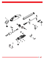
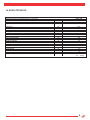
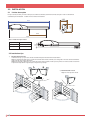
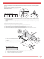
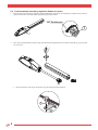
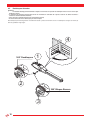
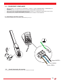
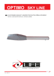
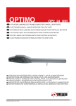
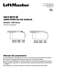
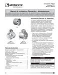
OPTIMO SKY LINE
ACTUADOR LINEAL ELECTROMECÁNICO PARA CANCELAS BATIENTES
INSTRUCCIONES Y ADVERTENCIAS PARA INSTALACION Y USO
Rev. 01 - 09/2011 RT
1
7
5RI17000
2
5RI17100
3
8
5RI17700
9
5RI17200
5RI17800
4
10
5RI17300
5RI17900
11
5
5RI17400
2
5RI18000
6
12
5RI17500
5RI18000
Ma
nua
l
AU
TO
M
AT
IC
DO
OR
O
PE
NIN
G
di i
str
i ist uzion
ruz i
ion
i
Ma
nua
le
ed
OP
T
TIM IMO
O
OP
1.0 DATOS TÉCNICOS
OPSL UNI
batientes con final carrera mecánicos.
Alimentación
Central LIFE: GE UNI R S DL / GEUNIR
V
V
OPSL UNI
230 Vac 50 Hz
230 Vac
Potencia max
W
A
160
1,4
Actuador electromecánico irreversible alimentado a 24 V para puertas
Absorción máx
Empuje
Lubrificación
Final carrera
Carrera útil del actuador
Temperatura de ejercicio
Grado de protección
Tiempo para abrir a 90º
Ciclo de trabajo
Peso actuador
Dimensiones
Uso en atmosfera ácida, salina o potencialmente corrosiva
Largo máximo y peso máx hoja
N
Tipo
1800
Grasa permanente
2 (Mecánicos)
mm
°C
IP
S
%
325
da -20 a +70
54
19
35
kg
mm
6,5
88
no
3 m - 150 kg
1 m - 350 kg
2.0 INSTALACION
2.1
Límites de empleo
EL tipo de cancela, la altura y la forma de las hojas; las condiciones climáticas, determinan los límites de empleo. Deben ser atentamente
considerados para la instalación. La tabla 3 tiene los valores sólo indicativos.
1 00
1 07
8 04
3 25
7 20
Tabla 2: Limites de empelo modelo
Peso máx de hoja (kg)
1,50
350
3,00
150
50
Largo máximo hoja
2.2 Instalacion tipo
1)
INSTALACION DE 2 HOJAS:
La definición de hoja 1 y hoja 2 de la cancela es fundamental para el funcionamiento del automatismo.
Hoja 1: Es la primera en abrirse (Fig 2.1) cuando las cancelas están cerradas, mientras que es la segunda en moverse cuando están abiertas.
Liega al tope de cierre después de la hoja 2.
Hoja 2: Es la segunda en abrirse (Fig 2.1) cuando las cancelas están cerradas, mientras que es la primera en moverse cuando se encuentran
en posición de hojas abiertas. Liega al tope de cerre primero que la hoja 1.
1
2
2) INSTALACION DE 1 HOJA:
Hoja 1: la única hoja de la cancela
1
1
2
2
.
Controntar que la cota “C” en la estructura no sea superior a los valores indicados en la tabla 3. Si la cota supera estos valores, es necesario aplicar
alguna prótesis simulada para llegar a los valores indicados en la tabla. Esto es para evitar que en cierre el actuador, vaya batiendo a golpes hasta
llegar al tope.
En la fig. están indicadas las cotas referidas para el montaje del actuador
En la tabla 3 están los valores de A Y B aconsejados para una
apertura de la hoja a 90º. (angle A).
.
!
#
"
$
Tabla3 : cotas de montaje actuador
Apertura
90°
A max
mm
B max
mm
C max
mm
D*
mm
160
160
70
710
$
(* D entre ojales máximo)
OP2005
Se aconseja de no elegir valores de A Y B demasiado diferentes entre ellos: de este modo se garantiza un movimiento regulado de la hoja con el
menor esfuerzo del actuador.
f
Cota A: Aumentándola se aumenta el ángulo de apertura y en consecuencia, disminuye el empuje del actuador, pero aumenta la velocidad
periférica.
f
Cota B: Aumentándola disminuye el ángulo de apertura y en consecuencia aumenta el empuje del actuador, pero disminuye la velocidad
periférica.
2.3 Posicionamiento soporte posterior y anterior
N-B Agujerear con broca (1) meter taco (2) apoyar el soportey (3) y atornillar (4) según fig. OP2007 del manual.
a)
b)
c)
d)
Definir la posición de fijación del soporte posterior del adtuador respetando las cotas A,B y C indicadas en tabla 3.
Verificar que la salida del tubo de los cables eléctricos se encuentren bajo el soporte (3).
Verificar que sobre la hoja, en el lugar donde debe ser fijado el soporte anterior del actuador, tengamos sitio para soldar o atornillar.
Fijar con tornillos (o soldadura) el soporte posterior al pilar en la posición establecida.
2
e)
Verificar que el soporte este perfectamente a nivel.
a1)
Lievar la hoja a la posición de cierre con el tope mecánico
de cierre.
Posicionar el soporte (1) anterior a la distancia E del soporte
posterior menor de 50 mm, según ilustración en .
b1)
3
1
4
D
Tabla 4: Cotas D y E de instalación
Cota (D)
Cota (E)
710 mm Max
0 mm
1
El valor de E tienen que ser apenas inferior 10 m/m de D, para permitir una mejor regulación de los finales de carrera.
c1)
Bloquear provisionalmente el soporte anterior con un sargento (2) .
d1)
Verificar que el soporte esté a nivel según ilustración en fig 4.
E
2.4
1.
Posicionamiento actuadory regulacion finales de carrera
Efectuar el bloque del actuador según indicado en capítulo DESBLOQUEO ACTUADOR. Para desbloquear el actuador meter la chaveta (1)
y girar a 360º anti-horario. El actuador quedará desbloqueado según figura OP2009.
360° Desbloqueo
1
A
2.
Sacar cobertor (3) destornillando (1) dando un golpe hacia delante para desengancharlo de los encastes. Desatornillar (4) y guiar el cobertor
por el visin fin (5).
3.
Levantar el actuador y meter el pernio del soporte en el ojo del soporte anterior del actuador (2)
1
2
8
.
4.
Meter el encaste en el ojo (5) del soporte posterior (3)y ensartar la horquilla del actuador (6) sobre el soporte (3) haciendo coincidir el agujero
con el encaste, meter tornillo (7) y apretar con el dado autoblocante (8) ver figura.
7
3
5
6
8
5.
6.
7.
8.
9.
Fijar el actuador (6) al soporte anterior (3) con tornillo.
Abrir y cerrar a mano la cancela más veces y verificar que el movimiento de la hoja es regular y que el actuador se mueva un plano paralelo
al plano de movimiento de la puerta.
Controlar que el soporte hembra del visinfin corra perfectamente por él, y que con la puerta cerrada o abierta, permanezca al menos 5 mmentre
el soporte corredizo y los finales de carrera.
Es necesario usar el agujero diferente sobre el soporte posterior repitiendo las operaciones indicadas en los puntos c) y d).
Definir con precisión las posiciones de apertura y cierre de las hojas de la puerta regulando las posiciones de las finales de carrera de la
siguiente manera:
§ Lievar la puerta a la posición de cierre; al tope mecánico;
§ Atrasar el final carrera de cierre (1) con la llave y ponerlo de modo que toque el soporte corredizo hembra. (5) Luego bloquearlo
fuertemente con el tornillo sin cabeza (6);
§ Lievar la hoja de la puerta a la posición de apertura deseada;
§ Atrasar el final carrera de apertura (2) con la llave y posicionamiento, de manera que toque el soporte corredizo hembra (5) luego
bloquear apretando el tornillo sin cabeza fuertemente (7).
1
2
5
6
10.
11.
12.
5
Fijar de modo definitivos el soporte anterior del actuador a la hoja eligiendo los medios necesarios según el material de la cancela,
(soldadura o tornillo).
Bloquear actuador según indicado en manual capítulo DESBLOQUEO ACTUADOR.
Montar cobertor de nuevo y el de aluminio antes sacados.
2.5
Desbloqueo Actuador
ATENCION:
v
El instalador deberfijar permanentemente la etiqueta concerniente a la operación de desbloqueo manual cerca de la llave para
desbloqueo manual;
v La activación del desbloqueo manual podría causar un movimiento no controlado de la puerta a causa de los daños mecánicos o
condiciones del balanceamiento mecánico;
v Antes de seguir la maniobra manual sacar la alimentación eléctrica;
v No hacer fuerza sobre la llave desbloqueo para evitar romperla.
Este desbloqueo permite desenganchar la transmisión del actuador y efectuar el movimiento a mano. El desbloqueo se consigue con la llave que
deber ser guardada en lugar seguro.
4
360° Desbloqueo
1
A
2
360° Bloque Barrera
3
10
.
3.0 CONEXIONES Y EMPALMES
f
f
f
f
Antes de proceder a las conexiones, leer atentamente lo indicado en capítulo PRESCRIPCIONES Y ADVERTENCIAS DE
SEGURIDAD;
El actuador debe estar conectado exclusivamente a la central de mando GE UNI R S DL fabricada por LIFE;
Todas las operaciones de conexión deben ser efectuadas sin tensión eléctrica. Si el dispositivo de desconexión no está a la vista,
poner cartel que diga: “ATENCION MANTENIMIENTO EN CURSO”;
El cableado interno del actuador electromecánico que han sido hechos en la fábrica no serán modificados.
3.1 Conexiones electricas actuador
Para acceder al cableado interno, mover cobertor (1) desatornillando (2) ver fig. A.
A
.IEGRO!")%24/
!ZUL#/-5.
"ROWN#%2#!
3.2
Central electronica del actuador
La central del mando electrónica utilizada es la GE UNI R DL, sea para una o dos hojas.
4.0 GENERAL INFORMATION
part of the manual is strictly forbidden without previous writt
ntegration. All rights on this document are reserved.
LIFE home integration will not accept responsibility for damage or malfunctions caused by incorrect installation or improper use of products and Users are therefore recommended to read this manual
carefully.
LIFE home integration will not accept responsibility for damage or malfunctions caused by the use of the automation together with the devices of other manufacturers; such action will render the
warranty void.
LIFE home integration will not accept responsibility for damage or injury caused by non-compliance with the installation, set up, maintenance and use indications contained in this manual and the
safety instructions described in the SAFETY INSTRUCTIONS AND WARNINGS chapter.
With the aim of improving its products, LIFE home integration reserves the right to bring about alterations to them at any time, without giving prior notice. This document conforms to the state of the
automation at which it is provided when released for sale.
INFORMATION ON THE MANUFACTURER
LIFE home integration is the manufacturer of the OPTIMO automation (and will hereinafter be referred to as manufacturer) and the owner of all rights concerning this document. The Manufacturer’s
information equired by Machinery Directive 98/37/EC is as follows:
LIFE home integration
Via S.Pertini, 3/5 – 31014 COLLE UMBERTO (TV) Italia
+ 39 0438 388 592
+ 39 0438 388 593
www.homelife.it
[email protected]
technician call-out and spares requests, Clients may contact the Manufacturer or area representative from whom the product was purchased.
INTENDE USE
f
f
f
f
f
f
f
f
f
OPTIMO is a low voltage, irreversible, articulated, mechanical operator designed exclusively for opening and closing one- and two-leaf residentialtype swing gates only. Improper
use or use on gates larger than those indicated in the TECHNICAL DATA and USAGE RESTRICTIONS chapters will be considered non-conform to the intended use. The
Manufacturer declines all responsibility for other use. The owner accepts full responsibility for improper use, which will result in the warranty being rendered void.
Any usage differing from that described above is forbidden.
The operator may not be installed or used in potentially explosive environments.
Motorised gates must conform to current European standards and Directives, including EN 12604 and EN 12605.
The operator may only be used when in perfect working order and in compliance with the intended use, in the awareness of safety and hazard conditions and in compliance with the instructions
for installation and use.
Any dysfunctions that may pose threats to safety must be eliminated immediately.
Do not use the operator in environmental conditions characterised by harsh atmospheric agents (e.g. salty air).
5.0 SAFETY INSTRUCTIONS AND WARNINGS
GENERAL INSTRUCTIONS AND WARNINGS
f
f
The Manufacturer declines responsibility for damage or injury caused by non-conformity with the information supplied concerning installation, trial run, use and maintenance
contained in this manual, and the failure to observe the safety instructions given below.
The installation, connection, testing, trial run and maintenance of the operator must be performed by a COMPETENT PERSON aided and supervised by a PROFESSIONAL
FITTER.
f
f
f
f
f
f
f
f
f
f
f
f
f
of mechanics, electronics and electrics, and of sector laws and standards.
Amateur installation IS STRICTLY FORBIDDEN as it does not comply with current standards and laws and therefore does not guarantee the safe operation of the automation.
Do not proceed with installation, connection and trial run in the event of doubts or indecision of any kind.
This manual must be read carefully and understood before installing the operator. If doubts arise during installation, contact a PROFESSIONAL FITTER or the
MANUFACTURER.
Only mount the operator on gates that are perfectly hinged and well balanced. A gate that is not correctly hinged and balanced can cause serious injury to the user and/or damage
to the operator.
The Manufacturer declines all responsibility for damage and faults to the operator caused by non-observance of
the instructions contained in this manual.
Keep this manual in a safe and easily accessible place so that it can be consulted rapidly when necessary.
During installation, connection, trial run and usage of the operator, observe all applicable accident prevention and safety regulations.
In the interests of safety and optimal functioning of the operator, only use original spares, accessories, devices and fastening apparatus.
Do not perform alterations to any operator device or component. This type of operation may cause malfunctions. The Manufacturer declines all responsibility for damage caused by products
The operator should not be used until the setting up procedure described in the STARTING UP chapter has been performed.
Should liquids penetrate inside the operator, disconnect the electricity supply and contact the Manufacturer’s Assistance Service immediately; use of the operator in such conditions may cause
hazard situations.
In the case of faults or problems that cannot be resolved using the information contained in this manual, contact the Manufacturer’s assistance service
STORAGE INSTRUCTIONS AND WARNINGS
The manufacturer declines all responsibility for damage and faults to OPTIMO operator functioning caused by non-compliance with the storage instructions.
f
f
f
The operator must be stored in closed, dry places, at room temperatures of between –20 and +70°C.
Keep the operator away from sources of
Keep the operator in a horizontal position,but not resting on the ground.
SAFETY INSTRUCTIONS AND WARNINGS INDICATIONS AND WARNINGS FOR USE
f
manual.
Moving gates usually present the following residual risks: impact and crushing against the main closure surface of the leaf or between the leaves; impact and crushing in the
guide and support parts during movement; mechanical risks caused bymovement.
The Manufacturer will not accept responsibility for damage or injury caused by the non-observance of the information on use contained in this manual, and the failure to observe
the safety indications given below.
The Manufacturer declines responsibility for damage and malfunctions caused by noncompliance with the instructions for use.
Keep this manual in a safe, easily accessible place, so that it can be consulted rapidly when necessary Before activating the gate ensure that all persons are at a safe distance.
Never touch the gate or moving parts when in motion.
Remain at a safe distance when the gate is in motion: only pass when the gate is completely open and immobile.
Do not allow children to play with gate controls, do not leave radio control or other control devices within children’s reach.
Prevent children from playing or standing in the vicinity of the gate or the control organs (radio controls), the same precautions should be adopted for disabled persons and animals.
In the event of malfunctions (noisiness, jerky movements, etc.) suspend the use of the automation immediately: failure to observe this rule may entail serious hazards, risks of accidents
and/or serious damage to the gate and the automation. Contact a PROFESSIONAL FITTER and in the meantime use the gate manually by disconnecting the operator (see the OPERATOR/
ACTUATOR RELEASE chapter).
f
f
f
f
f
f
f
f
f
f
FITTER.
Examine the installation frequently in order to ensure that there are no signs of mechanical unbalance, signs of wear and signs of damage to cables and assembled parts: do not use
automations that require repair work or adjustments.
Should liquids penetrate inside the operator, disconnect the power supply immediately and contact the Manufacturer’s Assistance Service; the use of the automation in such conditions may
cause hazard situations.
If a problem arises that cannot be resolved using the information contained in this manual, contact the Manufacturer’s assistance service.
f
f
f
INSTRUCTIONS AND WARNINGS FOR INSTALLATION
f
f
f
f
Before commencing installation read the SAFETY INSTRUCTIONS AND WARNINGS chapter carefully.
The COMPETENT PERSON who installs the operator is responsible for performing risk analysis and regulating the automation’s safety devices consequentially.
The Fitter must check that the temperature range declared on the operator (see TECHNICAL DATA Chap.)
is suited to the place in which the device is installed.
f
f
f
f
Before installing the operator, ensure that the gate is in good mechanical conditions, correctly balanced and that it opens and closes correctly.
Ensure that the risk of entrapment between the open gate and surrounding parts following the opening movement is eliminated.
Any normally open/off buttons installed for the activation of the operator must be positioned so that they are within view of the gate but distant from moving parts. Unless said
devices operate using keys, buttons be positioned at a minimum height of 1.5m and not accessible to unauthorised persons.
Once the automation has been installed, ensure that it is correctly adjusted and that the protection systems and release work properly.
f
f
caused by incorrect installation or poor maintenance of the gate. During installation, make constant reference to harmonised standards EN 12453 and EN12445.
Ensure that the individual devices to be installed are suitable for the automation that one intends to create, paying careful attention to the points raised in the TECHNICAL DATA
chapter. Do not proceed if even just one device is unsuitable for the intended use.
f
f
f
f
f
During installation, protect automation components to prevent liquids (e.g. rain) and/or foreign bodies (earth, gravel, etc) penetrating inside.
Wrapping materials must be disposed of in compliance with local regulations. Wear protective goggles when making holes for clamping.
In the event of works at heights of over 2m from the ground, for example for the installation of the indicator lamp or aerial,
Directive 89/655/EEC amended by 2001/45/EC.
PRELIMINARY CHECKS
Before commencing installation, the following checks must be performed:
1)
The weight and dimensions of the gate must not exceed the limits for use (see the TECHNICAL DATA and USAGE RESTRICTIONS chaps.), if they exceed such limits, the OPTIMO
operator may not be installed.
2)
The structure of the gate leaf must be suitable for the installation of the operator and conform to current standards. Provide all devices necessary to guarantee safe operation.
3)
The gate leaves must be sturdy and solid; the hinges must be suited to the dimensions and weight of the leaves, gaps between p
4)
The gate’s movement in both opening and closure must be uniform, without points of greater resistance to rotation or friction. Check manually by opening and closing the leaves several
times.
5)
The gate leaves must be well balanced, i.e. they must not move when left in any point during opening or closure. Ensure that the leaves not bend or deviate from their course during
movement.
6)
Gate leaf hinges must be perfectly vertical in order to avoid deviations during operation,
7)
In two-leaf gates, when completely closed the two leaves must meet and match perfectly for their entire height, without forcing one against the other or remaining too distant, and they
must be perfectly vertical.
8)
Check the opening and closure mechanical end stops; they must be:
•
•
adequately robust;
•
free from potential damage to the gate leaves in the event of collision.
9)
therefore it may not be installed too close to the ground.
10)
11)
g for metal tubes or screws and screw anchors for masonry).
6.0 MAINTENANCE
MAINTENANCE INSTRUCTIONS AND WARNINGS
f
f
f
f
f
f
f
f
f
f
f
f
f
f
Once the automation has been tested, the parameters set must NOT be altered. If further adjustments (e.g. alterations to the force value) are made, ALL THE CHECKS REQUIRED
FOR TESTING AND COMPLIANCE WITH STANDARDS MUST BE REPEATED.
The Manufacturer declines responsibility for damage or injury caused by non-compliance with the information provided in this manual and the safety instructions provided
below.
The Manufacturer declines all responsibility for damage and malfunctions deriving from noncompliance with the maintenance instructions.
Any checking, maintenance or repair work must be conducted by a PROFESSIONAL FITTER
Always switch off the electricity supply in the event of malfunctions, breakdowns and before any other operations in order to avoid the gate from being activated.
Always disconnect the operator’s power supply before performing any maintenance or cleaning operation.
The owner is not authorised to remove the operator cover as it contains live parts.
risks.
Use original spare parts, accessories and clamping material only.
In the event of intervention of automatic switches or fuses, before restoring function conditions identify and eliminate the fault. Request the intervention of a PROFESSIONAL
FITTER.
If a fault that cannot be solved following the information contained in the present manual arises, contact the manufacturer’s assistance service.
All maintenance, repair or replacement of parts must be recorded in the maintenance log, which is SUPPLIED AND INITIALLY FILLED IN BY THE FITTER.
CLEANING THE AUTOMATION
ATTENTION:
f
Never wash the operator with jets of water or cleaning devices using water.
f
Do not use corrosive substances, solvents, thinners or spirits to clean the operator.
f
Before cleaning switch of the power supply
a)
Automations are almost always installed outdoors and are therefore subject to climatic changes and harsh weather conditions that transport debris that may cause problems.
b)
The area in which the automation is installed must be kept clean to avoid malfunctions and faults.
c)
Keep the gate area clean by using a broom to brush away stones, gravel, mud etc. that deposit there.
d)
Keep the opening and closure stop plates clean
ROUTINE MAINTENANCE
Every 6 months a PROFESSIONAL FITTER should repeat the following operations:
f
f
Check that the gate performs the desired action.
f
Grease the gate’s bearings.
f
Repeat the series of tests described for automation testing
7.0 DEMOLITION AND DISPOSAL
f
The OPTIMO operator is constructed using various materials, which implies the adoption of different disposal procedures. Refer to regulations in force in the country in
which the automation is installed.
f
8.0 MANUFACTURER’S DECLARATION OF CONFORMITY
Declaration of conformity
under Directive 98/37/EC, appendix II, part B (Manufacturer’s Declaration of CE Conformity).
LIFE home integration
Via S/Pertini, 3/5
31014 COLLE UMBERTO (TV) – Italia
OPTIMO SKY LINE
Swinging gate operator
directives:
f
f
f
Machinery Directive 98/37/EC (formerly 89/392/EEC) and subsequent amendments,
Low voltage directive 73/23/EEC and subsequent amendments,
Electromagnetic compatibility directive 89/336/EEC and subsequent amendments.
f
f
f
f
f
f
EN 12445:2000 Industrial, commercial and garage doors and gates – Safety in the usage of motorised doors – testing methods
EN 12453:2000 Industrial, commercial and garage doors and gates – Safety in the usage of motorised doors - Requisites.
EN 60204-1:1997 Machinery safety – Electric equipment of the machine – Part 1: general rules.
EN 60950 Information technology equipment - Safety - Part 1: General requisites
ETSI EN 301489-3:2001 Electromagnetic compatibility for radio equipment and appliances.
EN 300220-3:2000 Radio equipment and systems – short band devices – Technical characteristics and testing methods for radio apparatus
with a frequency of 25 to 1000 MHz and powers of up to 500mW.
The Manufacturer also declares that it is not permitted for the abovementioned components to be used until such time as the system in
which they are incorporated is declared conform to directive 98/37/EC.
Nominativo del Firmatario:
MICHELE RUI
Qualifica:
Presidente
Firma:
_____________________
Address:
Telephone:
Telefax:
http
e-mail:
Via Sandro Pertini,3/5 31014 COLLE UMBERTO (TV) Italia
+ 39 0438 388592
+ 39 0438 388593
www.homelife.it
[email protected]