1
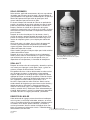
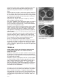
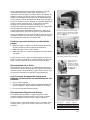
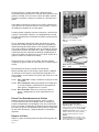
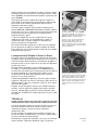
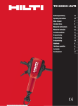
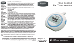
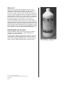
SEAL-ALL™
After years of research and development, here is a way to
impregnate and seal porosity, pin holes and fine cracks in cast
iron and cast aluminum cylinder heads and motor blocks.
This product makes all ceramic seals obsolete. No circulators, no
heaters, or special equipment required. Just pour Seal-All™ into
the water jacket. Wait one hour, or apply 10 PSI for 1 minute to
penetrate the leak. Pour excess out and store in the original bottle to reuse. Cure for 1 hour at 200°F or 8 hours at 72°F.
Seal-All™ outperforms ceramic sealants. It cross-links with
oxides (rust) inside the water jackets to form a tough, flexible lining that seals leaks and contains cooling systme pressures. Not
effected by water or coolant (anti-freeze). It prevents rust and corrosion; insulates and distributes heat evenly through the casting.
Seals porosity it welds and withstands engine operating temperatures. Seal-All™ is safe, easy, permanent and economical.
RESURFACING THE CASTING
Having completed adding and moving metal in the casting to
close the crack, the surface of the casting should then be
restored to its original condition.
For this purpose, Goodson supplies drills, rotary files, abrasive
grinding stones, and grinding mandrels and sleeves. See our
most current catalog for complete listings, or call for more information. Toll-free 1-800-533-8010 or direct at 507-452-1830.
© 1999, GOODSON SHOP SUPPLIES
P.O. BOX 847, AIRPORT INDUSTRIAL PARK, WINONA, MN 55987-0847
CR-MANUAL
Page 8
Order No. CPS-32 (32 oz. bottle) Also available
in a 1 gallon bottle, Order No. CPS-128.
Crack Repair Manual
CRK-150/350
PRODUCTS CO., INC.®
CR-MANUAL
INTRODUCTION
The Goodson crack repair process is a cold repair process for
repairing cracks in castings by adding metal and by moving the
metal in the casting to close the crack.
Just as castings vary in dimensions, in points of stress, and in the
development of cracks, likewise, the application of the crack
repair process must be both flexible and adaptable.
It is necessary initially to understand the basics of the cold crack
repair process. In applying the process during the repair of
casting, techniques for repairing specific cracks will evolve
naturally within the skill and experience of the particular operator.
This manual will discuss the repair of cracks generally, the
principles involved, and the tools and materials used. A few
examples will be given of the crack repair process applied to
engine castings and the injector seat area of diesel engine
heads.
It is our hope in preparing and presenting this crack repair
manual to be of further service to the engine repair and rebuilding
industry.
PRELIMINARY DISCUSSION
The crack repair process for cracks in metal castings involves
four basic steps:
1. Detection of the crack - determining the exact location and
extent of the crack.
2. Relieving the stress in the casting in the area of the crack
3. Adding and moving metal in such a way as to close the crack
4. Refinishing the surface of the repaired casting.
A fundamental advantage of the crack repair process is that
metal is added and moved to close the crack without subjecting
the casting to high temperature changes that take place in the
welding process. This avoids altering the physical characteristics
of the metal in the casting.
For example, the heat treating characteristics of the original casting are not altered when a crack in the casting is repaired
through the crack repair process. The hardness of the casting
remains exactly as it was before the repair of the crack.
This can be of importance in many instances. For example, in
some diesel engine heads where the injector hold is threaded,
welding that area of the casting may reduce the hardness of the
casting and increase the likelihood of subsequent stripping of the
threads in the injector hole when the injector chamber is torqued
into place. A repair of the injector area through the crack repair
process will avoid the effects of such temperature changes.
The crack repair process is not new. It has been in use successfully for many years. In addition to the normal repair of cracks on
flat surfaces of engine heads and block, one of the more common uses of the process has been the repair and replacement of
cracked and worn injector seat area in Cummins and GMC
Detroit Diesel engine heads. The cracked or worn area is reamed
out and tapped, then a tapered threaded plug is torqued into
place. The area is resurfaced and drilled, then a new seat is cut
to match the original configuration of the injector head. This application will be discussed in detail later in the manual.
CR-MANUAL
Page 2
and move the metal by torquing in of the plugs as well as by
peening.
Using a center punch, spot along both sides of the crack where it
is intended to drill. Tap and install the tapered plugs. The holes
should be spotted very close to the crack about 1/8” apart in a
lacing fashion alternately on the two sides of the crack.
After spotting the locations for the plugs along the line of the
crack, and before beginning to drill holes for the plugs, the entire
crack should be peened, always peening toward the center of the
crack.
After the crack has been peened, then drill and tap the holes for
the plugs.
The plugs should now be torqued into place. Torque the plugs in
a concurrent pattern. Do not torque in one plug all the way and
then move on to the next one.
After the plugs are torqued into place, cut off the part of the plugs
extending above the surface. Notch them with a small saw about
1/16” above the surface and break them off by tapping lightly with
a small hammer.
Now, the crack should be peened again. In addition, the stub
ends of the plugs should be peened.
In this type of repair, the crack is closed only by the moving of the
metal in the casting caused by torquing in plugs alongside of the
crack and by the peening. This is why the location of the plugs
and the peening of the casting are very important.
This photo shows a repair with the holes
drilled and tapped. Here, where the metal in the
casing is relatively thin, it is not usually
necessary to use a tapered reamer before
tapping the holes.
This photo shows a repair with plugs installed
and peened ready for resurfacing the casting.
CERAMIC SEAL
Ceramic seal, when properly applied, leaves a fine ceramic coating on the inside of the casting, which serves to close porosity
and the inside of minor cracks. It is applied to the casting after
the crack repair process is completed to give it a finishing touch
and added assurance that the crack is closed.
The head or block is remounted on a pressure tester and the
water ports are sealed so that the casting can be pressurized.
After pressurizing the head or block and confirming the quality of
your crack repair, secure the outlet and inlet hoses on the circulator and circulate the ceramic seal through the casting at the temperature supplied by the circulator.
After circulating the casting for a period of 15 to 30 minutes, close
off the return valve and then depress the air pressure button,
holding it down for a few seconds and then releasing it. This
pressure forces the ceramic seal in the casting out into the interior of any cracks and into any porosity in the interior of the casting.
Now, turn the head over, open the circulator return valve and
press the air pressure button for only a few seconds. This will
force the remaining liquid ceramic seal in the casting back into
the circulator tank.
Remove casting and set it to the side to allow the ceramic seal in
the interior of the casting to set or “fix.”
After a period of time, the ceramic seal will fix on the inside of the
casting and will serve as an additional seal to the crack. Time
required for the seal to set will vary depending upon the temperature and the humidity of the atmosphere.
Ceramic Seal (Order No. CRS-16) is pictured
above with the Goodson Crack Repair Kit
(Order No. CRK-350)
CR-MANUAL
Page 7
The repaired area is now ready for resurfacing and finish cutting
and installation of new valve seat.
In this kind of a repair, the crack is closed primarily by the adding
of more metal in the form of the plugs and by the peening of the
castings and the plugs. Accordingly, the positioning of the plugs
and the peening are very important parts of the repair.
TECHNIQUE #2
Installing tapered plugs along the line of the crack in readily
accessible areas of the casting that are not subjected to
high pressure and high temperature.
Metal castings, like most materials, have a degree of elasticity.
The technique discussed here is one that installs the plugs along
the line of the crack in a manner that takes advantage of this
elasticity in the metal.
After capturing the crack at both ends and installing plugs at each
end (as previously discussed), follow along the line of the crack.
Drill, ream, and tap holes along the line of the crack. Space the
plugs 1/4” to 1/2” apart. Here, the most widely used plug is the
Goodson CRP-235 plug which calls for the CRD-235 Drill, CRR235 Reamer and CRT-235 Tap.
If the metal at the point of repair is thin, normally it is not necessary to use the tapered reamer before tapping. However, if the
metal is more than 1/4” thick at the location of the drilled holes,
the tapered reamer should be used. With the tapered tap, the full
length of the tap is cutting, unlike a straight tap where the lead
threads do all of the cutting. Accordingly, where the metal is very
thick, it is necessary to ream the hole with a tapered reamer if the
tapered tap is to have a reasonable life.
Now, along the line of the crack, torque in the tapered plugs. The
plugs should be torqued in concurrently so that none of them will
be loosened as other plugs are torqued in. As the plugs are
torqued in, the crack will be forced open further. This will build up
in the metal a counter elastic pressure to push the crack closed.
After the plugs are all torqued into place, cut them off about 1/16”
above the surface of the casting. Do this by putting a nick in one
side of the plug with a small saw and breaking off the upper part
of the plug by tapping it lightly with a hammer.
Now peen the crack thoroughly. Peen from both sides of the
crack, always toward the center line of the crack. Then peen the
stub ends of each plug, always peening outwardly toward the
thread of the plug.
Here, the adding of the metal in the form of the tapered threaded
plugs, the moving
of the metal from the peening, and the built up elastic pressure of
the metal in the casting to spring back - all combine to close the
crack.
TECHNIQUE #3
Lacing the crack with plugs on both sides of the crack which
are not subjected to high pressure and high temperatures.
Another repair technique which is frequently used in areas where
the metal is not very thick, readily accessible and not subjected to
high pressure or temperatures is to lace the crack on both sides
CR-MANUAL
Page 6
This photo shows the same valve seat area
crack repair after the plugs have been cut off
and the area has been peened.
This photo shows the repair after resurfacing
and refinishing ready for installation of the new
valve seat.
As Goodson continues to offer new tools and techniques, the use
of the crack repair process continues to expand.
Cracks in metal castings are the result of stress or strain in a section of the casting. This stress or strain finds a weak point in that
section of the casting and causes the casting to distort or separate at the weak point.
Such stresses or strains in castings may develop because:
• The casting was subjected to pressure or temperature changes
before the casting was properly aged.
• The casting was subjected to excessive heat or excessive cold.
• The casting was sujected to a change in temperature that was
too rapid.
Whatever may have caused the crack, the important job is to
relieve the stress at the point of distortion or cracking. Then, add
more metal and move the metal in such a way as to close the
crack.
The Magnetic Crack Detection Kit 110V has
everything you need to find cracks in cast iron
heads and blocks. Order No. MM-300
DETECTION OF THE CRACK
Detecting a crack in a metal casting means not only finding that a
crack exists, but also determining the exact location and the
extent of the crack. It should be chalked or otherwise marked so
that it can be subsequently repaired.
With the Goodson crack repair process, cracks may be detected
by three processes:
1. Magnet and Magnetic Powder
2. Penetrant Dye (developed especially for non-magnetic cast
ings such as aluminum heads and blocks)
3. Leak Detection Plates
MAGNETIC CRACK DETECTION
With castings that react to magnetic charges, such as cast iron
engine heads or blocks, cracks often can be located by using a
magnet and magnetic powder.
First, clean the surface of the casting which is to be checked.
Remove oil and grease from the surface and leave the surface
dry and free of moisture.
Position the magnet on the surface of the casting and then gently
dust or drift magnetic powder onto the surface of the casting in
the area of the magnet. Where there is a crack in the casting, at
or near the surface of the casting, the magnetic powder between
the poles of the magnet will accumulate and show the existence
and location of the crack.
Since magnetic powder reacts this way only between the poles of
the magnet, it is necessary to move the magnet around on the
surface of the casting to check the area for cracks.
When the magnetic powder shows the existence and location of
the crack, the crack should then be completely chalked or otherwise marked so that it can be easily located later when the repair
is undertaken.
It is very important, after having detected a crack, to carefully outline the crack with chalk so that it can be easily identified after the
magnet is removed. As will be discussed later, it is also important
Position the magnet on the head surface. The
dust will clearly show cracks between the poles
of the magnet, even cracks below the surface.
The Compact MagnaRay Magnet is an ideal
alternative to the 110V
typw. It includes 1 lb.
powder and applicator
bulb.
Order No. MM-200
Magnaflux® Magnetic Powders from Goodson
Color ▼ 1 lb.
▼ 5 lbs.
▼ 25 lbs.
White WCD-100-G WCD-500-G WCD-2500-G
Yellow WCD-101-G WCD-501-G WCD-2501-G
Red WCD-103-G WCD-503-G WCD-2503-G
CR-MANUAL
Page 3
to move the magnet along the ends of the crack in order to find
the limits of the crack. Frequently, the crack that appears initially
does not totally relieve the stress in the casting and it is necessary to go beyond the apparent limits of the crack to relieve the
stress in the casting.
Position the magnet on the head surface. The dust will clearly
show cracks between the poles of the magnet, even cracks
below the surface.
DYE PENETRANT CRACK DETECTION
Many non-ferrous castings such as aluminum heads and blocks
do not respond to magnetic detection. For such castings, a dye is
used to show the cracks that are on the surface of the casting.
Goodson offers a reliable way to find cracks in aluminum castings
with its simple Alumni-Chek 3-step process:
AC-1 Cleaner – Clean and condition the area for the
Step 1
dye and developer.
AC-2 Penetrant – Spray penetrant on the cleaned
Step 2
and conditioned casting. Dye penetrates all surface
cracks and flaws.
AC-3 Developer – Spray on surface to turn cracks
Step 3
and flaws bright red in plain room light.
The Alumni-Chek Kit is an easy, reliable way to
find cracks in aluminum castings.
Order No. AC-KIT
NOTE: These sprays are also sold separately.
LEAK DETECTION PLATES
Goodson offers this simple, reliable test for leaks. Neoprenefaced metal plates seal the head to find flaws with pressure. Use
shop air and bubble fluid or a dip tank. Kit has main plate and all
smaller plates needed for that head. Air regulator, bolt set, and
bubble fluid are sold separately.
REPAIRING THE CRACK
Repairing the crack with the Goodson crack repair process
involves the use of tapered threaded plugs, drills of the correct
size, specially tapered reamers and specially made tapered taps.
Together with the PT-GUN and peening tools for use with the PTGUN.
The first step in making a repair is to stop or capture the crack.
This means to make certain that the limit of the crack created by
the particular stress in the casting is determined so that the repair
will cover the entire crack.
At the end of the crack, as detected, drill a hole using a drill suitable for a Goodson CRP-235 or CRP-235A plug. Then retest the
area to see if the crack runs beyond the hole. Continue this
process until you have definitely determined that the full extent of
the crack is established.
The particular technique or method to be used in repairing the
crack depends on the location and accessibility of the crack and
the thickness of the metal at the crack. Experience will develop
the most suitable techniques for each operator.
This manual will describe some of the most commonly used techniques in repairing cracks in engine and head blocks. These will
point the way toward the development by an operator of his own
approach to repairing specific cracks.
CR-MANUAL
Page 4
Leak Detection Plate Kits
Make
Engine
Chevy
Small Block
Big Block
GM
151 / 2.5L
1.8L / 2.0L / 2.2L
3.3L / 4.3L
173 / 2.8L
6.2L Diesel
Quad 4
Ford
255-351W
230 / 3.8L
171 / 2.8L (cars)
6.9L Diesel
Honda
EW1500
Chrysler “K” 2.2L
G53/54 (2.0/2.6L)
318, 340, 360
W8 - HP
Chry / Mitsu V6
Toyota
20R, 22R
Order No.
LDP-GM1
LDP-GM2
LDP-GM4
LDP-GM5
LDP-GM11
LDP-GM13
LDP-DS21
LDP-GM27
LDP-FO7
LDP-FO12
LDP-FO20
LDP-DS20
LDP-H3
LDP-CR2
LDP-CR3
LDP-CR4
LDP-CR4-HP
LDP-CR10
LDP-T4
Leak Detection Accesories
Air Regulator: Complete set-up fits all Plate Kits.
Includes gauge, air hose and pressure regulator.
Order No. LDP-BK
50-Bolt Set: 10 each of 5 lengths with washers
and nuts. Fast installation of Leak Plates.
Order No. LDP-BK
Bubble Fluid: (1/2 pint) Use with Leak Plates or
other air test systems. High viscosity fluid.
Order No. CRB-10
THE IMPORTANCE OF PEENING THE CRACK
Whatever technique is used in installing the tapered threaded
plugs, certainly one of the most important steps in the repair
process is the peening of the metal to move it to close the crack.
The proper use of the air hammer and peening tools to help close
the crack is an art that is learned only by practice.
For this peening process, Goodson offers the PT-GUN and a
variety of peening tools. The PT-GUN itself has 2 unique features. The primary advantage of the gun is its total position control over the peening tool. In addition, it has a swivel which
permits it to be used either in a pistol grip fashion or in a straightaway fashion.
When peening the metal in the crack area, always peen in toward
the center line of the crack. Do not peen down the middle of the
crack or away from the line of the crack.
After the tapered plugs have been installed and cut off, as an
added measure, peen the stub end of the plug. Again, always
peen outwardly toward the outside of the plug. It is there at the
thread that you are making certain there will be no leak.
The Pnuematic Drive Gun (Order No. PT-GUN)
is included with the Goodson Crack Repair Kit
(Order No. CRK-350) and is also sold
separately.
Goodson offers a wide selection of Threaded
Plugs, HSS Drills, Extension Drills, Tapered
Reamers and Tapered Taps. Please call toll-free
1-800-533-8010 (or 507-452-1830) for more
information.
TECHNIQUE #1
Installing tapered plugs along the line of the crack in areas
of the casting that are subjected to high pressure and temperatures.
One of the best examples of this type of crack is one in the valve
seat area of a head. Here the metal is relatively thick and the
area is subjected to high pressures and temperatures.
In this situation, the plugs are installed at angles to the casting
surface, not perpendicular to the casting surface. In addition, they
are installed in an overlapping fashion.
Normally, one plug hole is drilled, reamed and tapped. The plug
is fully torqued in place and the excess part of the plug is cut off
before the next hole is started. This permits a better location of
the next plug so that it will overlap the preceding plug, not only at
the surface but below the surface as well.
Where the metal in the casting is relatively thick, after drilling the
hole, it should be reamed with a tapered reamer before tapping
with the tapered tap. With the tapered tap, the full length of the
tap is cutting and the hole must be tapered if the tap is to have a
reasonable life.
The next step after installing the plugs and cutting off the excess
ends is to peen the crack.
However, before peening the crack area and the ends of the
plugs, a rough cut should be made on the valve seat cutter for
installing the new valve seat, there will be a minimum of
disturbance of the peening.
After roughing in the valve seat area, thoroughly peen the crack
area and the installed plugs. It is in situations like this that the
total position control feature of the PT-GUN is so important. For
example, with the peening tool with the curved tip, the PT-GUN
allows you total control of the position of the peening tip.
Again, when peening the casting, always peen toward the center
line of the crack. When peening the ends of the plugs, always
peen toward the outer edge of the plug.
This photo shows the first stage of a valve seat
area repair. For illustrative purposes only, all of
the plugs have been left in position (the excess
parts of the plugs have not been cut off) to
show the angles at which they have been
installed so that they overlap both on the
surface and below the surface of the casting.
CR-MANUAL
Page 5
SELLO CERÁMICO
Sello cerámico, applicado correctamente, deja una capa adentro
del molde, que sirve para cerrar los poros y el parte adentro de
grietas pequeños. Está applicado al molde después de que haya
terminado el processo de reparación de grietas para darlo
certeza addicional que esté cerrada la grieta.
El cabeza o bloque está montado de nuevo en un probador de
presión y los puertos de agua están sellados para que el molde
puede ser presurizado. Después de presurizar la cabeza o el
bloque y confirmar la calidad de su reparación de la grieta,
asegure las mangeras de cala y salida en el circulator y circule el
sello cerámico a través del molde a la temperatura suministrada
por el circulator.
Después de circular el molde por 15 a 30 minutos, cierre la
válvula de regreso y presione el botón del presión de aire. Este
presión se hace que el sello cerámico en el molde salga en el
interior de cualquieras grietas y en cualquier poro adentro del
molde.
Ahora, dale vuelta a la cabeza, abra la válvula de regreso del
circulator, y presione el botón del presión de aire sólo por
algunos segundos. Esto forzará el restante líquido en el molde
adentro del tanque del circulator.
Quite el molde y póngalo al lado para dejar que el sello cerámico
adentro del molde se seque.
Después de un rato, el sello cerámico se secará adentro del
molde y servirá como un sello addicional a la grieta. El tiempo
que necesitará para que se seca el sello puede variar y es
dependente en la temperature y la humedad del atmosphero.
No. de pieza CPS-32 (botella de 32 onzas).
También disponible en una botella de un gallon,
No. de pieza CPS-128.
SEAL-ALL™
Después de muchos años de investigación y desarollo, acquí hay
una manera para impregnar y sellar poros, hoyos, y grietas en
cabezas y bloques de hierro colado y aluminio.
Este producto los hace caído en desuso todos los sellos cerámicos. No ocupa circulators, ni calentadoras, ni otro equipaje
especial. Sólo echale en el abrigo del agua. Espere una hour o
applique 10 PSI por un minuto para penetrar la filtración. Saque
el exceso líquido y póngalo en la botella original para usar otra
vez. Curelo por una hour a 200°F o por 8 horas a 72°F.
Seal-All™ supera todos los sellos cerámicos. Mezcla con los
oxidos adentro del abrigo de agua para formar un foro durable, y
flexible que selle las filtraciónes y contenga pressiónes que
refrescan. No le afecta agua, ni anti-congelante. Previene oxidación y corrosión. Aisla y distribuye el calor uniformemente por
el molde. Sella los poros y resiste a las temperaturas operadoras
del motor. Seal-All™ es seguro, permanente, y económico.
REVESTIR EL MOLDE
Haber terminado de agregar y mover el metal en el molde para
cerrar la grieta, la surficie del molde debe, entonces, ser restaurado a su condicón original.Por este propósito, Goodson suministra taladros, limas rotarias, piedras abrasivos, y mandríles y
camisas que muelen. Veese a nuestro catálogo por listas completas, o llame por más información. Gratis a 1-800-533-8010 o
directamente a 507-452-1830.
© 1999, GOODSON SHOP SUPPLIES
P.O. BOX 847, AIRPORT INDUSTRIAL PARK, WINONA, MN 55987-0847
CR-MANUAL
Page 8
Manual de Reparación de Grietas
CRK-150/350
PRODUCTS CO., INC.®
CR-MANUAL
INTRODUCTÍON
El processo de reparación de grietas de Goodson es un
processo de reparación frío para reparar grietas en moldees
agregando metal y moviendo el metal en el molde para cerrar la
grieta.
Así como los moldees cambian de dimension, de puntas de
estrés, y desarollo de grietas, igualmente el aplicación del
processo de reparación de la grieta tiene que ser adaptable y
flexible.
Es necessario al principio comprender los básicos del processo
de reparación de grietas frío. En applicar el processo durante la
reparación de molde, técnicas para reparación de grietas
específicas evolucionará con el talento y la experiencia del
operador.
Este manual descutirá la reparación de grietas en general, los
principios implicados, y las herramientas y materiales utilizados.
Unos ejemplos serán dado sobre el processo aplicado a moldees
de motores y el area del asiento del inyector en los motores
diesel.
Es nuestra esperanza que en preparando y presentando este
manual ser de servicio addicional a la industria de reparación y
reedificación de motores.
DISCUSIÓN PRELIMINAR
El processo de reqaración de grietas para las grietas en moldees
de metal implica cuatro pasos básicos:
1. Descubrimiento de la grieta- determinación de la ubicación
exacta y el extensión de la grieta.
2. Aliviar el estrés en el molde en la area de la grieta.
3. Agregar y mover metal en una manera que cerrará la grieta.
4. Barnizar la surficie del molde que ha sido reparado.
Una ventaja fundamental del processo es que metal estara
agregado y movido para cerrar la grieta sin subjectar el molde a
los cambios en tempuratura que pasen en el processo de
soldadura. Esto evita el riesgo de estar cambiando las
carcterísticas físicas del metal adentro del molde.
Por ejemplo, las características de estar tratado al calor del
molde original no cambiarán cuando una grieta esté reparada por
el processo de reparación de grietas. La dureza del molde se
queda exactamente igual como era antes de la reparación de la
grieta.
Esto pueda ser importante en muchas instancias. Por ejemplo,
en algunos cabezas de motores de diesel en cuales el agujero
del inyector es enhebrado, soldar esa area del molde puede
reducer la dureza del molde y aumentar la probabilidad de pelar
los hilos adentro del agujero en cuando la cámara del enyector
está doblado en lugar. Una reparación de la area del enyector a
través el proceso evitará los efectos de estos cambios de temperatura.
CR-MANUAL
Page 2
consiguiente, donde el metal es muy gruesa, es necessario
insertar la rima al hoyo con una rima cónica si quiera que el
manchuelo dura bastante.
Ahora, por la linea de la grieta, doble los tapónes en lugar. Los
tapónes deben estar doblado uno después del otro para que
ninguno aflojará cuando los otros están puestos. Con meter los
tapónes, abrirá más la grieta. Esto aumentará un presión
contrario-elástico en el metal para cerrar la grieta.
Después de que todos los tapónes están puestos cortelos 1/16”
arriba de la surficie del molde. Para hacer esto melle un lado del
tapon con un serrucho pequeño y pege el parte arriba con un
martillo para romperlo.
Ahora, hay que golpear la proa a la grieta completamente.
Hágalo de los dos lados a la grieta, siempre hacia la linea en el
centro de la grieta. Después golpea la proa a los fines de los
tapónes, siempre hacia afuera al parte afuera del tapon.
Acquí, la adición de metal en la forma de los tapónes cónicos, el
movimiento del metal de haberlo golpeado la proa, y el presión
contrario-elástico del metal en el molde, combinen para cerrar la
grieta.
Esta photo muestra una reparación con los
agujeros taladrados y con machuelos
instalados. Acquí, donde el metal en el molde
es relativemente delgado, normalmente no es
necesario usar una rima cónica antes de
insertar el machuelo.
TÉCNICA #3
Atar la grieta con tapónes en ambos lados de la grieta que
no sean sujetos a presión y temperatureas altos.
Una otra técnica de reparación utilizado frequentemente en areas
donde el metal no es muy grueso, es accessible, y no es sujeto a
presión y temperaturas altos, es atar la grieta en ambos lados y
doblar los tapónes en lugar o golpear la proa para mover el
metal.
Utilizando un punzón, pega por los dos lados de la grieta donde
piensa taladrar. Inserte el machuelo y, después, los tapónes
cónicos. Los hoyos deben de quedar muy cerca a la grieta, 1/8"
aparte, y en una manera de atera alternamente en ambos lados
de la grieta.
Después de haber escogido las ubicaciónes por los tapónes por
la linea de la grieta, pero antes de empezar a taladrar los hoyos
por los tapónes, será necesario golpear la proa a toda la grieta,
siempre hacia el centro de la grieta.
Después de haber golpeado la proa a la grieta, taladre los hoyos
y inserte los machuelos.
Ahora doble los tapónes en lugar. Haga esto todos al mismo
tiempo. No se debe de meter completamente un tapon y
después los otros.
Depsués de que los tapónes estén en lugar, corte el parte de los
tapónes que queda arriba de la surficie. Mellelos con una serrucho pequeño 1/16" arriba de la surficie y pegelos con un martillo
para que se rompen.
Ahora, hay que golpear la proa a la grieta otra vez. También a los
tapones.
En esta tipa de reparación, la grieta está cerrado solo con el
movimiento del metal en el molde causado por haber doblado los
tapónes al costado de la grieta y por haber golpeado la proa.
Esto es porque la ubicación de los tapónes y golpear la proa al
molde son muy importantes.
Esta foto muestra una reparación con los
tapones instalados y listo para revestir el
molde.
Sello Cerámico (No. de pieza CRS-16) es
imaginado arriba con el Equipo de Reparación
de Grietas de Goodson (No. de pieza CRK-350).
CR-MANUAL
Page 7
excesso está cortado antes de empezar el próximo hoyo. Esto le
permita una ubicación major del próximo tapon para que le
queda arriba del primero, no solo a la surficie pero también
abajo.
Donde el metal en el molde es relativamente grueso, después de
taladrar el hoyo, deba de insertar una rima cónica antes de insertar un machuelo cónico. Con el machuelo cónico, la longitud total
del machuelo está cortando y el hoyo tiene que ser cónico para
que el machuela dura bastante.
El próximo paso, después de instalar los tapones y cortar los
fines, es golpear la proa de la grieta.
Pero, antes de golpear la proa del area de la grieta y los fines de
los tapones, debe de cortar el cortador del asiento de válvula
para la instalación del asiento nuevo, así habrá menos alboroto
del area que ha sido golpeado la proa.
Después de haber cortado el area del asiento de válvula, golpee
la proa al area de la grieta y los tapónes. En stiucaiones como
este la característaca que tiene el PT-GUN de control total es
muy importante. Por ejemplo, con la herramienta para golpear la
proa con la punta curva, el PT-GUN le deja tener control del posición de la punta.
Otra vez, en golpeando la proa al molde, siempre hágalo hacia la
linea del centro de la grieta. En golpear la proa al fines de los
tapónes, siempre hágalo hacia afuera del parte afuera del tapon.
El area reparado es, ahora, listo por revestimiento y cortos
finales, y la instalación del Nuevo asiento de válvula.
En esta tipa de reparación, la grieta está cerrado principalment
por agregar más metal en la forma de los tapones y por golpear
la proa de los moldees y los tapónes. Por consiguiente, la posición de los tapónes y golpear la proa son partes muy importantes
de la reparación.
TÉCNICA #2
Instalar tapónes cónicos por la linea de la grieta en areas
accesibles del molde que no son sujetos a presión y
temperaturas altos.
Moldees de metal, igual a casi todos materiales, tienen un grado
de elasticidad. La técnica discutida acquí es una que instale los
tapónes por la linea de la grieta en una manera que toma ventaja
de la elasticidad en el metal.
Después de capturar la grieta por los dos fines y instalar tapónes
en cada fin (como ya hemos discutido), sigua por la linea de la
grieta. Taladre y inserte rimas y machuelos en los hoyos por la
linea de la grieta. Ponga los tapónes _” a _” aparte. Acquí el
tapon más utilizado es el CRP-235 de Goodson, que necesita el
taladro CRD-235 de Goodson, la rima CRR-235 de Goodson, y
el machuelo CRT-235 de Goodson.
Si el metal a la punta de reparación es delgado, normalmente no
es necessario usar la rima cónica antes de insertar el machuelo.
Pero, si el metal sea más que _” de grueso a la punta de los
hoyos taladrados, hay que usar la rima. Con el machuelo cónico,
la longitude total del machuelo está cortando. No es así con un
machuelo normal en que sólo las roscas adelantes cortan. Por
CR-MANUAL
Page 6
Esta foto muestra el mismo area del asiento de
válvula después de que se hayan cortado es
exceso de los tapones y el area haya sido
golpeado la proa.
Esta foto muestra la reparación después de
revestir y barnizar y listo para la instalación del
asiento de válvula nuevo.
No es nuevo el proceso de reparación de grietas. Ha estado
usado exitosamente por muchos años. Además que la
reparación normal de grietas en surficies planas de cabezas de
motores y bloques, uno de los usos más communes ha sido la
reparación y reemplazo de areas de asientos de inyectores que
ya no sirven en cabezas de motores de diesel. En el area que ya
no sirve se instera una rima y después un machuelo, después se
inserta un tapon roscado en lugar. El area estará revistido y
taladrado y un asiento nuevo estará cortado igual a la
configuración original de la cabeza del inyector. Esta applicación
será discutido más tarde en el manual.
Cuando continuamos ofreciéndole herramientas y técnicas, el
uso del proceso para reparación de grietas sigue expandiendo.
Grietas en moldees de metal son el resulto de estrés en un parte
del molde. El estrés busca un lugar en acquel parte del molde y
causa distorción o serparación a la punta débil.
El equipaje magnético para descubrir grietas
110V tiene todo que necesitará para descubrir
grietas en cabezas y bloques de hierro colado.
No. de pieza MM-300
Pueda ser que estos estréses han desarollado
porque:
1. Molde fue sujeto a cambios en presión o temperatura antes
de que el molde se habia envejecido correctamente.
2. Molde fue sujeto al calor o frío excesivo.
3. Molde fue sujeto a un cambio en temperatura que fue demasiado rápido.
Lo que sea que causó la grieta, el trabajo importe es eliminar el
estrés a la punta de distorción o agrietar. Después agregue más
metal y mueva el metal en una manera que cerrará la grieta.
Descubrimiento de la Grieta
Descubrimiento de una grieta en un molde de metal incluye no
sólo provechar que exista una grieta, pero también determiner la
ubicación exacta y el extensión de la grieta. Debe maracar la grieta para que se puede estar reparada subsiguientemente.
Ponga el imán en la surficie de la cabeza. El
polve mostrará claremente grietas entre las
astas del imán, también debajo de la surficie.
El imán compacto de
Magna-Ray es un
alternativo al equipaje
110V. Incluye una libra
de polvo y su bombilla
applicadora. No. de
pieza MM-200.
Con el proceso de reparación de grietas de
Goodson, grietas pueden ser descubritos por tres
procesos:
1. Imán y Polvo Magnético
2. Tinte de Penetrante (hecho especificamente por moldes que
no son magnéticos, como cabezas y bloques de aluminio)
3. Placas para Descubrimiento de Grietas
Descubrimiento Magnético de Grietas
Con moldees que reaccionen a cargos magnéticos, como
cabezas o bloques de hierro colado, muchas veces se puede
encontrar las grietas usando un imán y polvo magnético.
Primero, limpie la surficie del molde que vaya a chequear. Quite
cualquier acete y grasa de la surficie y dejela seca y libre de
humedad.
Polvos magnéticos de Magnaflux® de Goodson
Color ▼ 1 lb.
▼ 5 lbs.
▼ 25 lbs.
Blanco WCD-100-G WCD-500-G WCD-2500-G
AmarilloWCD-101-G WCD-501-G WCD-2501-G
Rojo WCD-103-G WCD-503-G WCD-2503-G
CR-MANUAL
Page 3
Ponga el imán en la surficie del molde y después echale
suavimente polvo magnético en el area del imán. Donde hay una
grieta en el molde, en o cerca de la surficie del molde, el polvo
magnético acumulará y mostrará la existencia y ubicación de la
grieta.
Como polvo magnético reacciona en esta manera sólo entre las
astas del imán, es necessario mover el imán por toda la surficie
del molde para chequear el area por grietas.
Cuando el polvo magnético muestre la existencia y ubicación de
la grieta, la grieta debe, entonces, ser completamente marcado
para que se puede estar encontrado fácilmente cuando empiece
la reparación.
El equipo de Alumi-Check es una manera facil y
segura de descubrir grietas en moldes de
aluminio. No. de pieza AC-KIT.
Nota: Estos rocíos también se venden
separados.
Es muy importante, después de haber descubrido una grieta,
resuma con cuidado la grieta con tiza para que se puede estar
identificada después de que quite el imán. Como discutiremos
más tarde, también es importante mover el imán por los fines de
la grieta para encontrar los límitos de la grieta. Frequentamente,
la grieta que aparece al principio no elemine completamente el
estrés en el molde y es necesario ir más allá de los límitos de la
grieta para eliminar el estrés en el molde.
Ponga el imán en la surficie de la cabeza. El polvo mostrará
clarimente las grietas entre las astras del imán, y también bajo la
surficie.
Descubrimiento de Grietas Usando Tinte Penetrante
Muchos moldees que no son ferrosos como cabezas y bloques
de aluminio, no reaccionan al descubrimiento magnético. Por
estos moldees, un tinte mostrará las grietas que están en la surficie del molde.
Paso 1 AC-1 Limpiador- Limpie y condicione el area por el tinte
y revelador.
Paso 2 AC-2 Penetrante- Rocie el penetrante en el molde que
ya ha sido limpiado y condicionado. El tinte penetrará
todas grietas y desperfectos en la surficie.
Paso 3 AC-3 Revelador- Rocie en la survicie para que las
grietas y desperfectos se mirran rojo brillante in luz
normal.
Placas Para Descubrimiento de Grietas
Goodson le ofrece esta prueba de grietas sencilla y segura.
Placas metales forradas con neoprene sellan la cabeza para
encontrar desperfectos usando presión. Use aire y fuido de burbujas o un tanque de depresión. El equipo incluye la placa principal y todas las placas más pequeños que necesitaría. Regulador
de aire, fuido de burbujas, y juego de tornillos se venden por
separado.
Reparar la Grieta
Reparar la grieta usando el proceso de reparación de grietas de
CR-MANUAL
Page 4
Equipos de Placas para Descubrir Grietas
Marca
Motor
No. de pieza
Chevy
Bloque pequeño
LDP-GM1
Bloque grande
LDP-GM2
GM
151 / 2.5L
LDP-GM4
1.8L / 2.0L / 2.2L
LDP-GM5
3.3L / 4.3L
LDP-GM11
173 / 2.8L
LDP-GM13
6.2L Diesel
LDP-DS21
Quad 4
LDP-GM27
Ford
255-351W
LDP-FO7
230 / 3.8L
LDP-FO12
171 / 2.8L (cars)
LDP-FO20
6.9L Diesel
LDP-DS20
Honda
EW1500
LDP-H3
Chrysler “K” 2.2L
LDP-CR2
G53/54 (2.0/2.6L)
LDP-CR3
318, 340, 360
LDP-CR4
W8 - HP
LDP-CR4-HP
Chry / Mitsu V6
LDP-CR10
Toyota
20R, 22R
LDP-T4
Accesorios para Descubrir Grietas
Regulador del Aire: : Le queda a todos los
equipos de Placas. Incluye calibrador, mangera,
y regulador de presión. No. de pieza LDP-BK
Conjunto de 50 cerrojos: Incluye 10 cerrojos de
cada de 5 tamaños con tuercas y arandelas.
Instalación rápido de placas.No. de pieza
LDP-BK
Fluido de Burbujas: Use con placas o otras
sistemas de probar de aire comprimido. Fluido
de viscosidad alta. No. de pieza. CRB-10.
Goodson implica el uso de tapones roscados y cónicos, taladros
del tamaño correcto, rimas cónicas y machuelos cónicos. Juntos
con el PT-GUN y las herramientas para golpear la proa para uso
con el PT-GUN.
El primer paso en hacer la reparación es parrar o capturar la
grieta. Esto incluye asegurarse que el límito de la grieta creado
por el estrés en el molde ha sido determinado para que la
reparación cubre toda la grieta.
Al fin de la grieta, taladre un hoyo usando un taladro por los
tapones CRP-235 y CRP-235A de Goodsoon. Después chequea
el area otra vez a ver si la grieta corre atras del hoyo. Sigua este
proceso hasta que esté seguro que haya determinado el
extension total de la grieta.
La técnica o método que usa en la reapración de la grieta
depende en la ubicación y la accesibilidad de la grieta y la
anchura del metal a la grieta. Experiencia desarollará las
técnicas mejores por cada operador.
Este manual describirá algunos de las técnicas más populares
para la reparación de grietas en motores y bloques de cabeza.
Estos apuntarán hacia el desarollo por un operador de su propio
enfoque de reparar grietas.
La pistola neumática (No. de pieza PT-GUN)
para instalar está incluido con el equipo de
reparación de grietas de Goodson (No. de pieza
CRK-350). También se vende separada.
Goodson le ofrece una selección grande de
tapones roscados, taladros de acero de
alto-fuerza, taladros de extension, rimas
cónicas, y machuelos cónicos. Por favor llame
gratis a 1-800-533-8010 (o a 507-452-1830)
por más información.
La Importancia de Golpear la Proa a la Grieta
Uno de los pasos más importantes en el proceso de reparación
es golpear la proa del metal para moverlo para cerrar la grieta. El
uso correcto del martillo neumático y herramientas de golpear la
proa para ayudar a cerrar la grieta es un arte que será apprendido sólo con practica.
Por este proceso de golpear la proa, Goodson le ofrece el
PT-GUN y un variedad de herramienta. El PT-GUN tiene dos
características extraordinarias. El ventaja primaria de la pistola es
su control completo de la herramienta para golpear la proa.
También tiene un giratorio que le permite usarla como una
pistola o en una manera derecha.
Cuando esté golpeando la proa en el area de la grieta, siempre
hágalo en la dirección de la linea al centro de la grieta. Nunca se
debe de golpear la proa en el centro de la grieta, ni hacia afuera
de la linea de la grieta.
Después de que los tapones cónicos hayan estado instalados y
cortados, como un paso extra, golpee la proa del fin del tapon.
Otra vez, siempre golpea la proa hacia afuera del parte afuera
del tapon. Ahí es donde está asegurandose que no vaya a haber
otra grieta.
Esta foto muestra el primer paso de la
reparación de un area de un asiento de válvula.
Por propósitos ilustrativos, todos los tapones
están en lugar todavía (no se han cortado los
partes excesos de los tapones) para mostrar los
ángulos a que han sido instalado para que se
superpongan arriba y abajo de la surficie del
molde.
TÉCNICA #1
Instalar tapones cónicas por la linea de la grieta en areas del
molde que están sujetos a presión alto y temperaturas altas.
Uno de los ejemplos mejores de esta tipa de grieta es una en el
area del asiento de válvula de la cabeza. Acquí el metal es
relativemente grueso y el area está sujeto a presión y
temperaturas altos.
En este situación, los tapones están instalados a ángulos a la
surficie del molde, no perpendicular a la surficie. También deben
de estar instalados uno arriba del otro.
Normalmente, un hoyo está taladrado, y una rima y un machuelo
están insertados. Tapon está doblado en lugar y el parte de
CR-MANUAL
Page 5