1
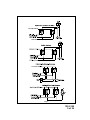
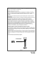
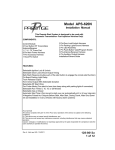
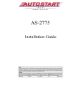
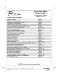
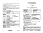
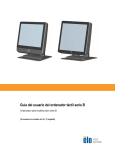
Model PA-620C
Installation Manual
This Remote Start System is designed to be used with
Automatic Transmission-Fuel Injection Vehicles Only!
COMPONENTS:
Control Module
2 Four Button RF Transmitters
Antenna/Receiver
1 1” X 1.75” Foam Pad
6 Pin Main Power Harness
7 Pin Accessory Harness
1 Hood Pin Switch
5 Pin Receiver Harness
3 Pin Parking Light/Ground Harness
2 Door Lock Harness
4 Pin Auxiliary Output Harness
DBI Port For Data Bus Module Applications
Installation/Owners Guide
FEATURES:
* Selectable Ignition Lock and Unlock
* Selectable Door Lock/Unlock Output Timing
* Safe Start (Requires double push of the start button to engage the remote start function)
* On Board Parking Light Relay
* Trunk Release Output
* Horn Chirp Output With Selectable Duration
* Selectable RF Start Chirp
* Car Finder Mode (Can elect to have horn beep along with parking lights if connected)
* Selectable Run Times 5, 10, 15, or 20 Minutes
* Selectable Gas or Diesel
* Pathway Illumination Selectable On Arm, On Disarm, On Both or Off
* Automatic Start Timer
(Can be set to start your car automatically at 2 or 4 hour intervals)
* 4 Negative Pulsed Aux Outputs Before Start, After Start, During Crank, After Shut Down
(To aid installation in many vehicles with factory alarm systems)
FCC NOTICE
This device complies with part 15 of the FCC rules. Operation of this device is subject to the following
conditions:
(1) This device may not cause harmful interference, and
(2) This device must accept any interference received, including interference that may cause undesired
operation.
Caution: Changes or modifications not expressly approved by the party responsible for compliance voids the
users authority to operate this device.
Page 1
128-9108
1 of 24
INSTALLATION OF THE MAJOR COMPONENTS:
CONTROL MODULE: (P/N 136-5272)
Select a mounting location inside the passenger compartment (up behind the dashboard).
The mounting location selected must be within 24" of the ignition switch wiring harness to
allow connection of the 6 pin main wiring harness.
Be certain that the chosen location will not interfere with proper operation of the vehicle. Avoid
mounting the module to or routing the wiring around the steering shaft/column, as the module
or wiring may wrap around or block the steering wheel preventing proper control of the vehicle.
Secure the module in the chosen location using cable ties or screws as necessary.
Do Not Mount The Module In The Engine Compartment, as it is not waterproof.
THE RECEIVER/ANTENNA VALET SWITCH LED ASSEMBLY: (P/N 1181246)
The Superheterodyne Receiver Antenna Assembly which includes the LED and Valet/Programming switch provided with this unit allows routing from below the dash board for maximum
operating range. Choose a location above the belt line (dashboard) of the vehicle for best
reception. Special considerations must be made for windshield glass as some newer vehicles
utilize a metallic shielded window glass that will inhibit or restrict RF reception. In these vehicles, route the antenna toward a rear window location for best reception. Secure the antenna
with double stick tape provided. After securing the antenna with tape, we advise also securing a
section of the antenna cable to a fixed support. This will prevent the antenna from dropping down
in case the double stick tape is exposed to extreme heat which may loosen it's gummed surface.
Route the connector toward the control module using caution not to pinch the cable as this will
cause poor or no RF reception to the control module. Connect the 5 pin cable to the mating
connector of control module.
HOOD PIN SWITCH: (P/N 1363699)
The pin switch included in this package is intended for protecting the hood area of the
vehicle. In all cases, the switch must be mounted to a grounded metal surface. When
the pin switch is activated, (hood/trunk open), it will supply a ground to the input wire
activating the alarm. In addition, the hood switch is required for the safety shut down of
the remote start unit. If the vehicle is being worked on, this hood switch prevents the
remote start activation even if the RF command to start is issued. WARNING: This switch
must be installed in all applications. Failure to do so may result in personal injury
or property damage.
Mount the switch in the hood locations away from water drain paths. If necessary, a
bracket may be used to move the switch away from rain gutters or allow mounting to the
firewall behind the hood seal. In both cases the switch must be set up to allow the hood to
depress the switch at least 1/4 inch when the hood is closed and fully extended when the
hood is opened. For direct mounting, a 1/4 inch hole must be drilled. Carefully check
behind the chosen location to insure the drill will not penetrate any existing factory wiring or
fluid lines.
Drill a 1/4" hole in the desired location and thread the pin switch into it using a 7/16" nut
driver or deep well socket. If using the mounting bracket, first secure the bracket to the
desired location and secure the pin switch in the pre-threaded mounting bracket hole.
DO NOT PLUG THE SIX PIN MAIN POWER HARNESS OR THE MULTI PIN INPUT /
OUTPUT HARNESS INTO THE CONTROL MODULE UNTIL ALL CONNECTIONS TO THE
VEHICLE HAVE BEEN MADE. AFTER SELECTING YOUR TARGET WIRES AS DEFINED BELOW, DISCONNECT THE NEGATIVE BATTERY CABLE FROM THE VEHICLE
BATTERY PRIOR TO MAKING ANY CONNECTIONS.
Page 2
128-9108
2 of 24
Note: Do not remove the fuse holders from this wire harness.
Fuses must be used and located as close as possible to the power
source for adequate protection of the vehicle.
WIRING THE 6 PIN MAIN POWER HARNESS Connector (P/N 4120110)
Fused RED/WHITE TRACE WIRE: + 12 volt Battery 1 Source 20A Max
Locate the vehicle battery wire(s) at the ignition switch. Verification: These wires will register
voltage in all positions of the ignition switch. Connect the Red w/White wire to the vehicle's battery
wire. This wire provides power for the control circuit as well as the ignition 1 and ignition 2 relays.
Fused RED WIRE: + 12 Volt Battery 2 Source 30A Max
Locate the vehicle battery wire(s) at the ignition switch. Verification: These wires will register
voltage in all positions of the ignition switch. Connect the Red wire to the vehicle's battery wire.
This wire provides power for the start relay and the accessory relay.
PURPLE Wire: Starter Output
Careful consideration for the connection of this wire must be made to prevent the
vehicle from starting while in gear. Understanding the difference between a mechanical and an electrical Neutral Start Switch will allow you to properly identify
the circuit and select the correct installation method. In addition you will realize
why the connection of the safety wire is required for all mechanical switch configurations.
WARNING: Failure to make this connection properly can result in personal injury
and property damage.
In all installations it is the responsibility of the installing technician to test the remote start
unit and ensure that the vehicle cannot start via RF control in any gear selection other than
park or neutral.
In both mechanical and electrical neutral start switch configurations, the connection of the
Yellow wire will be made to the low current start solenoid wire of the ignition switch harness.
This wire will have +12 volts when the ignition switch is turned to the start (crank) position
only. This wire will have 0 volts in all other ignition switch positions.
PINK Wire: Ignition 1 Output
Connect this wire to the ignition 1 wire from the ignition switch. This wire will show +12 volts
when the ignition key is turned to the "ON" or "RUN" and the "START" or CRANK"
positions, and will have 0 volts when the key is turned to the "OFF" and "ACCESSORY"
positions.
PINK/WHITE Wire: Ignition 2 Output
Connect this wire to the ignition 2 wire from the ignition switch. This wire will show + 12
volts when the ignition key is turned to the "ON" or "RUN" position and is some cases the
"START" or CRANK" position. This wire will show 0 volts when the key is turned to the
"OFF" and "ACCESSORY" positions.
NOTE: See programming information (Bank 3 Selection # 6) concerning this wire to allow
output during the "START" mode.
Page 3
128-9108
3 of 24
ORANGE Wire: Accessory Output
Connect this wire to the Accessory wire from the ignition switch. This wire will show + 12
volts when the ignition switch is turned to the "ACCESSORY" or "ON" and "RUN" positions, and will show 0 volts when the key is turned to the "OFF" and "START" or "CRANK"
positions.
Wiring The 2 Pin Door Lock/Unlock Harness Connector (P/N 4120106)
The Green & Blue Door Lock/Unlock output wires provide a pulsed ground output to control the
vehicle door lock / unlock circuits. The output of these wires has a maximum switching capability
of 250 mA. Many vehicles today have factory door lock relays which can be connected directly to
these outputs, however always confirm that the factory relays in your particular vehicle do not
exceed the rated 250mA output of the units door lock/unlock circuit. Plug the 2 pin connector of the
door lock/unlock harness into the mating connector shell of the control module. Determine the
door lock circuit of the vehicle you are working on and wire according to the diagrams shown.
3 Wire Negative Switched Door Lock Circuits:
In this application, the Green wire of the 2 pin harness provides a negative pulse during the
arming sequence. Connect the Green wire to the low current negative signal wire from the
factory door lock switch to the factory door lock relay.
The Blue wire of the 2 pin harness provides a negative pulse during the disarming sequence.
Connect the Blue wire to the low current negative signal wire from the factory door unlock
switch to the factory door unlock relay.
Negative Type Door Lock Circuits
Page 4
128-9108
4 of 24
Page 5
128-9108
5 of 24
Wiring The 4 Pin Auxiliary Output Harness, Connector (P/N 4120102)
The auxiliary 4 pin connector provides low current outputs to control various functions in
the vehicle during different stages of the Remote Start unit's operation. Understanding
these outputs and the time in which they occur will allow you to determine if they are
needed for the particular vehicle you are working on as well as how to use them.
Green/Black Wire: Pulsed Negative Output Before Start
The Green/Black wire will provide a 1 second 250 mA pulsed negative output 1.5 second before
the remote start unit activates as well as when the transmitter is used to disarm the system.
Typical use for this output would be to disarm a factory theft deterrent system to prevent false
triggering of the factory alarm when the remote start unit engages or when the transmitter is used
to unlock the doors.
NOTE: This output can be selected to operate like the door lock output as set in alarm feature
setting #1 by selecting feature #13 of Bank 3 to "as door unlock pulse".
Light Blue Wire: Pulsed Ground Output After Start
The Light Blue Trace wire will provide a 1 second 250 mA pulsed ground output after the vehicle
is started under control of the remote start unit. Typically this wire will be used to re-lock the
vehicle doors if the doors unlock automatically when the factory anti-theft system is disarmed.
Green/White Wire: Pulsed Ground Output After Shutdown
The Green/White wire will provide a 1 second 250 mA pulsed ground output after the remote start
unit shuts down and the G.W.R. O/P turns off. This output will occur regardless of whether the
circuit times out or is manually terminated. Typically this output will be used to re-lock the vehicle
doors if the doors unlock automatically when the ignition circuit transitions to off.
Black/Yellow Trace Wire: Ground Output During Start (Crank)
The Black/Yellow wire will provide a 250 mA ground output while the starter output of the remote
start unit is active. This output can be used to activate the Crank Low/Bulb Test wire found in some
GM vehicles. This wire is also referred to as the ECM wake up wire in some Chrysler vehicles.
NOTE: The outputs above are low current outputs and must be used with a relay if the circuit's
requirement is more than 250 mA.
5 Wire Antenna Receiver Connector (P/N 4120192)
Connect the mating end of the previously mounted receiver harness to the mating connector
on the module. This harness will be the supply for the LED, Valet Switch as well as the RX
& TX of the receiver.
3 Pin Parking Light Input/Output & Ground Harness, Connector (P/N 4120103)
Black Wire: Chassis Ground Source
Connect the Black wire to a known vehicle ground source or to a solid clean metal part of
the chassis. Be certain to remove any paint or grease and secure this wire with a self
tapping screw and ring terminal.
White w/ Red Trace Wire: Parking Light Supply Input
This wire is the common contact of the on board parking light flasher relay. If the vehicle you
are working on has +12 volt switched parking lights, connect this wire to a fused + 12 volt
source. (Max. 15 Amps)
NOTE: If the vehicle's parking lights are negative switched, connect this wire to chassis
ground.
Page 6
128-9108
6 of 24
White Wire: Parking Light Flasher Output
This wire is the normally open contact of the on board parking light flasher relay. Connect
this wire to the vehicle parking light feed wire.
7 Pin Accessory Input/Output Harness, Connector (P/N 4120107)
Brown/Red Wire: Brake Positive Inhibit Input
The Brown/Red wire provides an instant shutdown for the Remote Start Control module
whenever it gets + 12 volts. If the Brake lights switch in the vehicle switches + 12 volts to
the brake light circuit, connect the Brown/Red wire to the output side of the brake switch.
This will allow the Remote Start to shut down if an attempt is made to operate the vehicle
without the key while running under the control of the Remote Start. In most vehicles, in
order to shift into gear, the brake pedal must be depressed. The brake input will in turn
cause the remote start unit to shut off.
Gray Wire: Negative Inhibit Input
The Gray wire provides an instant shutdown for the Remote Start Control Module whenever
it is grounded. Connect the gray wire to the hood pin switch previously installed.
This wire must be routed through a grommet in the firewall and connected to the hood pin
switch. If the pin switch is to be used with an alarm system, connect this wire using a diode
assembly.
WARNING: DO NOT RELEASE THIS VEHICLE TO THE CONSUMER UNTIL YOU
CONFIRM THE OPERATION OF THE HOOD PIN SAFETY SHUT DOWN FEATURE.
IMPORTANT! This connection is a safety wire and must be connected to a hood pin switch
and tested as described. Failure to do so may result in personal injury or property damage.
This wire may also be used if the vehicle brake light circuit switches ground to the brake
lights. An isolation diode must be used for ground switched brake light circuits and must be
connected to the output of the brake switch.
To test this circuit, while the vehicle is running under control of the remote start unit, open
the vehicle’s hood. The remote start unit should shut down immediately. If not, check the
wiring to the control module and the under hood pin switch.
WARNING: DO NOT RELEASE THE VEHICLE TO THE CONSUMER IF THIS CIRCUIT
DOES NOT PERFORM AS SPECIFIED.
Purple/White Wire: Tachometer Input Signal
This wire will continually monitor the engine's tach rate while the unit is under power of
the Remote Start module. Route this wire to the vehicle ECM tach input or through the
firewall into the engine compartment and connect to the negative side of the ignition coil.
This Remote Start unit learns the tach rate of the vehicle and in most cases will operate
properly from one multi coil pack regardless of the number of cylinders.
If the vehicle has a single coil unit for each cylinder, it may be necessary to connect to
one of the vehicles electronic fuel injector wires for proper RPM signal.
Red/White Wire: Delayed 250mA Pulsed Channel 3 Output
The Red/White wire supplies a 250mA ground pulsed output whenever channel three of the
receiver is accessed. Pressing the pre-programmed transmitter button for three seconds
will access this feature. This is a low current output and must be connected to a relay to
supply power to the trunk release or the circuit you wish to control. Connect the Red/White
wire to terminal # 86 of a VF45F11 P&B relay or equivalent. Connect terminal # 85 of the
Page 7
128-9108
7 of 24
relay to a fused + 12 volt source. Connect the common, normally open, and normally
closed contacts of the relay to perform the selected function of channel 3.
Brown/Black Wire : 250 mA Horn Output
The Brown/Black wire is provided to beep the vehicle’s horn. This is a transistorized
low current output and should only be connected to the low current ground output
from the vehicle’s horn switch. If the vehicle uses a + 12 VDC horn switch, then
connect the black w/ white trace wire to terminal 86 of the AS 9256 relay ( or an
equivalent 30 Amp automotive relay ),and connect relay terminal 85 to a fused
+ 12 VDC battery source. Connect relay terminal 87 to the vehicle’s horn switch
output, and connect relay terminal 30 to a fused + 12 VDC battery source.
Blue/Black Wire: Ground Output While Running Under Remote Start Control
This wire provides a 250mA ground output that becomes active 3 seconds before the
Remote Start module initializes and remains grounded while the module is active
plus an additional 4 seconds after the system turns off. In all of the applications
described below, a relay will be required.
The Blue/Black wire can be used to accommodate the following situations:
A. Shock Sensor By Pass:
B. Additional Ignition Output:
C. GM VATS Key Override:
Black/White Wire: Entry Illumination Ground Output
This wire provides a 30 second ground output (250 mA Max.) whenever the remote is
used to disarm the alarm or to unlock the doors and provides a continuous pulsed
output whenever the alarm or car finder feature is active. This wire should be connected to an external relay and wired to the vehicles interior entry lighting whenever
the optional feature is desired.
Programming Tach Rate:
NOTE: All applications require that tach be programmed.
The unit will not operate unless tach is programmed. If an attempt is made to start the vehicle
via the remote start without first programming tach, the unit will flash the parking lights 7 times
indicating tach has not been learned and stored. If the tach rate is not properly programmed
for the specific vehicle, the unit may not realize that the vehicle is running and in certain
instances re-engage the starter motor.
The Remote Start Unit will learn the tach rate of most vehicle's single coil, multiple coil
packs, or single injector. To learn tach:
1. Turn the ignition key to the On position.
2. Press and release the valet/program push button switch 3 times.
3. Immediately turn the ignition key Off.
4. Press and hold the valet/program push button switch, then start the vehicle using the
key.
5. When the unit senses the tach signal, the parking lights will begin to flash.
6. Wait for at least 5 flashes
7. Release the valet/program switch. The parking lights come on for three seconds to
indicate that the learned tachometer signal is stored and the unit is out of the
tachometer learn mode.
NOTE: If the unit fails to learn tach rate due to an improper tachometer connection or a
poor tach source, the parking lights will not flash. To correct this situation, locate and
connect the Purple/White wire to the proper tach signal, and then repeat the tach learn
routine.
Page 8
128-9108
8 of 24
Setting Up The System Programmable Features:
Bank 1 Transmitter Programming Channels
Start with the system disarmed, turn the ignition switch to the on position then:
1) Press and release the push button valet/program switch 3 times.
Siren Chirps once and or Lights flash one time indicating the transmitter program mode
successfully entered.
See Owners Manual for transmitter programming.
Turn the ignition switch off then on to access Bank 2 Keyless / Alarm feature selections. 1 chirp +1 long chirp +1 flash then the ignition transitions off, followed by 1 long
chirp / 2 lights flashes when the key is turned on indicates that you are in feature
selection of bank 2
When the key transitions off and 2 long chirps / 3 light flashes when the key transitions
on.
Press the pushbutton switch:
1 time to access the first selection as shown below. Use the lock button of the
transmitter to change the feature selection or press the pushbutton to advance to the
next selectable feature.
Bank 2
Feature
1 Chirp/Flash
2 Chirp/Flash 3 Chirp/Flash 4 Chirp/Flash 5 Chirp/Flash 6 Chirps/Flash
1stDoor Lock/UL
1S/1S
3.5 S/3.5S
2nd Accy Lock
Auto Lock On
Auto Lock Off
3rd Accy. UL
Auto UL On
Auto UL Off
4th Horn Chirp
10mS
16mS
1 S/Dbl 1 S.
Dbl 1/1 S
Dbl 1/Dbl 1
Default
1S L/350mS ul
1S/1S.
Auto Lock Off
Auto UL Off
30mS
40mS
5th Chp Del TX
On
Off
6th Park Lights
Normal
On 15 Sec
On 15 Sec
On 15 Sec.
With Lock
With U/L
w/ L & U/L
50mS
16mS
Off
Normal
When finished setting the keyless/alarm selectable features, turn the ignition off then
on to advance to Bank 3, Remote Start Selectable Features.
1 Flash when the key transitions off and 3 chirps/light flashes when the key transitions on.
Press the pushbutton switch one time to access the first selection as shown below.
Use the lock button of the transmitter to change the feature selection or press the
pushbutton to advance to the next selectable feature.
Bank 3
Feature
1 Chirp/Flash
2 Chirp/Flash
1 RF Start Chirp
Off
On
2 Run Time
5 Min.
10 Min.
3 Park Lights
On Steady
4 Input Check
Voltage
3 Chirp/Flash 4 Chirp/Flash 5 Chirp/Flash 6 Chirps/Flash
Default
On
15Min.
20 Min.
Flash
Tach
10 Min
Steady
DBI Tach
Tach
5 Voltage Level
> 0.5V B4 Start < 0.5V B4 Start
> 0.5
6 Ign. 2 Select
Off With Crank On With Crank Same As Accy
On With Crank
7 Diagnostics
Off
On
Off
8 Crank Time
0.8Sec
1.0 Sec
1.5 Sec
9 Gas/Diesel
Gas
Diesel 10
Diesel 15
10 Green/Black
Single Pulse
As D/UL Pulse
Single
ADS
2.0 Sec
Diesel 20
1.0
Gas
(Aux O/P)
11 DBI Select
ADS
Trilogix
12 Time Start
2 Hours
4 Hours
4 Hours
Page 9
128-9108
9 of 24
TIMED START OPERATION:
To begin the start timer, within 10 seconds of turning off the ignition switch, activate the RF
command to start 2 times. (Press the start button four times). The lights will flash and the siren
will chirp 2 or 4 times. Indicating timed interval mode has been initiated. The vehicle will automatically start every 2 or 4 hours as programmed. To cancel the timed start mode start the
vehicle either by RF or by the ignition key.
Diagnostics:
Enter Bank 3 and turn on selectable feature # 7 as described in the feature selection and
setting section.
Exit the feature selection mode then press and hold the pushbutton valet/program switch
and then turn the ignition switch to the on position.
NOTE: Diagnostic mode is a temporary mode. Once you have accessed the diagnostic
mode, the unit will pause for two seconds then begin to flash the last stored shut down
code. This code will be displayed three times in succession, then the unit will automatically exit the diagnostic mode.
The parking lights will flash a number of times indicating the reason for the last remote start
shutdown. The light flash indications are as follows:
1
2
3
5
6
7
8
Flash
Flashes
Flashes
Flashes
Flashes
Flashes
Flashes
Run timer expired
Low or no tach signal (RPM)
Positive inhibit wire activation
RF shutdown signal received, or manual start trigger wire reactivated.
High tach signal (RPM)
Tach signal has not been learned
Negative inhibit wire activation
4 PIN DATA BUS PORT (DBI Port)
The 4 pin port located on the side of this module is for proprietary Audiovox data bus interface
modules. These modules are used to access a variety of features in the vehicle which can be as
simple as door trigger inputs, to more complex door lock outputs, or transponder interfaces for
remote starting. DO NOT connect anything to this port other than the Audiovox DBI interface
modules or damage to the Remote Start will occur. All installation instructions for the DBI
modules will be packaged with the individual component along with the proper 4 pin wiring
harness requires to access the data transmit & receive as well as the proper voltage levels for
the interface.
Page 10
128-9108
10 of 24
COMPLETING THE INSTALLATION:
After you have confirmed the operation of the Audiovox Remote Start unit and tested all the safety
features of the system:
1. Mount the control module up and behind the dash securing it in place with cable ties or
screws. Be certain that the chosen mounting location will not inhibit any of the controls of
the vehicle.
2. Securely harness and tie all wiring up and away from all hot and moving parts that they may
come in contact with under the dash board or in the engine compartment areas.
CAUTION: Particularly avoid the area around the steering shaft and column, as wires can
wrap around these mechanisms and impair the safe operation of the vehicle.
3. Apply the Caution Labels supplied with this kit to a conspicuous area in the engine compartment. Make sure to clean the surface before affixing the label.
4. Check the vehicle's wipers, lights, horn, etc.... to insure proper operation.
5. Replace all panels that were removed during installation, and retest the system.
6. Explain all activated features and safety systems associated with Remote Start Unit installed
to the customer.
FCC NOTICE
This device complies with part 15 of the FCC rules. Operation of this device is subject to the following
conditions:
(1) This device may not cause harmful interference, and
(2) This device must accept any interference received, including interference that may cause undesired
operation.
Caution: Changes or modifications not expressly approved by the party responsible for compliance
voids the users authority to operate this device.
Page 11
128-9108
11 of 24
For technical support go to www.prestigecarsecurity.com or call 1 800 225 6074
© 2012 Audiovox Electronics Corporation, Hauppauge, NY 11788
128-9108
Page 12
128-9108
12 of 24
Modelo PA-620C
Manual de instalación
Este sistema de arranque remoto está diseñado para ser
utilizado con Transmisión-Fuel inyección vehículos
automáticos sólo!
COMPONENTES:
Módulo de control
2 Cuatro transmisores de botón RF
Antena/receptor
1 Almohadilla de espuma de 1 “x 1.75”
Arnés de alimentación de 6 pin principal
Arnés de accesorio de pin 7
1 Interruptor de clavija de capo
Arnés de receptor de 5 pin
Mazo de cables de luz de estacionamiento/
tierra pin 3
Arnés de bloqueo de puerta 2
Haz de salida auxiliar de 4 pines
DBI puerto para aplicaciones de módulo de
Bus de datos
Guía de instalación/propietarios
CARACTERÍSTICAS:
*
*
*
Ignición seleccionable bloquear y desbloquear
Temporización de la salida bloquear/desbloquear de puerta seleccionable
Safe Start (requiere doble pulsación del botón start para activar la función de arranque
remoto)
* A bordo relé de luces de estacionamiento
* Tronco versión salida
* Claxon Chirp salida con duración seleccionable
* Seleccionable RF Inicio Chirp
* Car Finder modo (puede elegir tener cuerno junto con las luces de estacionamiento si
conecta una señal sonora)
* Seleccionable Run Times 5, 10, 15 o 20 minutos
* Seleccionable de Gas o Diesel
* Estacionamiento selección luz para encender por 15 segundos con bloquear,
desbloquear, bloquear y desbloquear o no bloquear o desbloquear
* Inicio automático (Se puede configurar para iniciar su coche automáticamente a
intervalos de 2 ó 4 horas)
* 4 Negativo pulsante Aux salidas antes de comenzar, después del inicio, durante el
arranque, después del cierre hacia abajo
(Para ayudar en la instalación en muchos vehículos con sistemas de alarma de fábrica)
Page 13
128-9108
13 of 24
Instalación de los componentes principales:
Módulo de control: (P/N 136-5272)
Seleccione una ubicación de montaje dentro del compartimiento de pasajeros (hasta
detrás del tablero). La ubicación de montaje seleccionada debe estar dentro de los 24 “del
mazo de cables del interruptor de encendido para permitir la conexión del mazo de cables
principal de 6 pines.
Asegúrese de que la ubicación elegida no interfiera con el funcionamiento del vehículo.
Evite montar el módulo o enrutamiento del cableado alrededor del eje/columna de
dirección, como el módulo o el cableado puede envolver alrededor o bloquear el volante
evitando un control adecuado del vehículo. Fijar el módulo en la ubicación elegida mediante
bridas o tornillos según sea necesario.
No, no instale el módulo en el compartimento motor, ya no es impermeable.
La antena con el valet switch y LED: (P/N 1181246)
La Asamblea de receptor superheterodino que incluye el interruptor valet/programa permite
enrutamiento debajo del tablero para rango máximo de operación. Elija una ubicación
encima de la línea de banda (dashboard) del vehículo para una mejor recepción.
Consideraciones especiales deben hacerse para parabrisas ya que algunos vehículos
más recientes utilizan un cristal blindado metálico que inhiben o restringir la recepción de
RF. En estos vehículos, dirija la antena hacia una ubicación de la ventana trasera para una
mejor recepción. Fije la antena con doble cinta de palo proporcionada. Después de fijar la
antena con cinta, aconsejamos asegurar también una sección de cable de la antena a un
soporte fijo. Esto evitará que la antena se caer en caso de que la cinta de doble palo está
expuesta a temperaturas extremas que pueden aflojar su superficie engomada. Dirija el
conector hacia el módulo de control con cautela para no pellizcar el cable ya que esto
causará pobres o sin recepción de RF al módulo de control. Conecte el cable de 5 pines en
el conector del módulo de control.
Interruptor de clavija de campana: (P/N 1363699)
El interruptor de clavija incluido en este paquete están diseñados para proteger el área de
la campana del vehículo. En todos los casos, el interruptor debe montarse sobre una
superficie metálica conectada a tierra. Cuando se activa el interruptor de clavija, (capó/baúl
abierto), suministrará una tierra para el hilo de entrada de activación de la alarma. Además,
el interruptor de la campana es necesario para la seguridad en el cierre de la unidad de
arranque remoto. Si el vehículo se está trabajando, este conmutador campana impide la
activación de arranque remoto incluso si se emite el comando de RF para iniciar. Este
interruptor debe instalarse en todas las aplicaciones. Advertencia: No hacerlo puede
resultar en lesiones personales o daños a la propiedad.
Montar el interruptor en las localidades de campana lejos de rutas de drenaje de agua. Si
es necesario, puede utilizarse un soporte mueva el interruptor de canalones o permitir el
montaje del firewall detrás el sello de la campana. En ambos casos que el interruptor debe
ser configurado para permitir la campana oprimir el interruptor al menos 1/4 de pulgada
cuando la campana está cerrada y completamente extendida cuando se abre la campana.
Para montaje directo, se debe perforar un agujero de 1/4 de pulgada. Revise
cuidadosamente detrás de la ubicación elegida para asegurarse de que el taladro no
penetrará cualquier cableado de fábrica existente o líneas fluidas.
Taladre un orificio de 1/4 “en la ubicación deseada y enrosque el interruptor de pin mediante
un controlador de tuerca de 7/16” o la toma de pozo profundos. Si utiliza el soporte de
Page 14
128-9108
14 of 24
montaje, primero Fije el soporte a la ubicación deseada y fije el interruptor de clavija en el
orificio del soporte de montaje prerroscados.
NO CONECTE EL ARNÉS DE ALIMENTACIÓN PRINCIPAL DE SEIS PIN O, EL MÚLTIPLE DE
ENTRADA CONECTOR EN EL MÓDULO DE CONTROL, HASTA QUE HAN REALIZADO
TODAS LAS CONEXIONES AL VEHÍCULO. DESPUÉS DE SELECCIONAR SU DESTINO LOS
CABLES COMO SE DEFINE A CONTINUACIÓN, DESCONECTE EL ALAMBRE NEGATIVO DE
LA BATERÍA DE LA BATERÍA DEL VEHÍCULO ANTES DE HACER CONEXIONES.
CABLEADO el 6 PIN conector de alimentación principal del arnés (P/N 4120110)
Fusible alambre rojo/blanco: + 12 voltios batería 1 fuente 20A Max
Localice los alambres de batería de vehículo en el interruptor de encendido. Verificación:
Estos alambres registran tensión en todas las posiciones de la llave. Conecte el alambre
rojo de w/blanco al alambre de la batería del vehículo. Este alambre proporciona energía
para el circuito de control, así como el encendido 1 y encendido 2 relés.
Fusible alambre rojo: + 12 voltios batería 2 fuente 30A Max
Localice los alambres de batería de vehículo en el interruptor de encendido. Verificación:
Estos alambres registran tensión en todas las posiciones de la llave. Conecte el rojo
alambre al alambre de la batería del vehículo. Este alambre proporciona energía para el
relé de arranque y el relé auxiliar.
Alambre purpura: Salida de arranque
Un examen cuidadoso para la conexión de este alambre debe hacerse para evitar que el
vehículo arranque en velocidad. Comprender la diferencia entre un sistema mecánico y un
interruptor de arranque neutro eléctrico permitirá correctamente identificar el circuito y
seleccionar el método de instalación correcta. Además te darás cuenta por qué es
necesaria para todas las configuraciones del interruptor mecánico la conexión del alambre
de seguridad.
Advertencia: Si no se realiza esta conexión correctamente puede resultar en lesiones
personales y daños a la propiedad.
En todas las instalaciones es responsabilidad del técnico instalación para probar la unidad
de arranque remoto y asegurarse de que el vehículo no se puede iniciar mediante control
de RF en cualquier selección de marchas distintas park o neutral.
En tanto mecánico como eléctrico neutro iniciar configuraciones de switch, se hará la
conexión del alambre amarillo para el alambre baja actual del solenoide de arranque del
cableado del interruptor de encendido. Este alambre tendrá + 12 voltios cuando se activa el
interruptor de encendido a la posición de inicio (manivela) solamente. Este alambre tendrá
0 voltios en las demás posiciones del interruptor de encendido.
Alambre rosa: Salida de encendido 1
Conecte este alambre al alambre de ignición 1 del interruptor de encendido. Este alambre
tendrá + 12 voltios cuando la llave de encendido en “ON” o “RUN” y el “Inicio” o manivela”
posiciones y tendrá 0 voltios cuando la llave esté en la posición “OFF” y “Accesorio”.
Alambre rosa/blanco: Salida de encendido 2
Conecte este alambre al alambre de ignición 2 del interruptor de encendido. Este alambre
tendrá + 12 voltios cuando la llave de encendido a la “ON” o “RUN” posición y algunos
casos el “Inicio” o manivela”posición. Este alambre mostrará 0 voltios cuando la llave esté
en la posición “OFF” y “Accesorio”.
Page 15
128-9108
15 of 24
Nota: Vea información (Banco 3 selección # 6) relativa a este alambre para permitir la salida
durante el modo “Arranque” de programación.
Alambre naranja: Salida de accesorio
Conecte este alambre al alambre accesorio del interruptor de encendido. Este alambre
tendrá + 12 voltios cuando el interruptor de encendido esté en el “accesorio” o “ON” y “RUN”
posiciones y mostrará 0 voltios cuando la llave esté en la posición “OFF” y “START” o
“CRANK”.
Alambreado de la cerradura de puerta de 2 pines / desbloquear el conector del arnés
(P/N 4120106)
El verde & azul cerradura de la puerta y los alambres de salida de desbloqueo proporcionan
una salida de pulso negativo para controlar la cerradura de la puerta de vehículo /
desbloquear el circuito del relé. La salida de estos alambres tiene un máximo de
conmutación capacidad de 250 mA. Hoy, muchos vehículos tienen relés de cerradura de
puerta de fábrica que puede ser conectado directamente a estas salidas, sin embargo
siempre confirme que los relés de fábrica en su vehículo particular exceda la salida 250mA
nominal del circuito de bloqueo/desbloqueo de puertas unidades. Enchufe el conector de 2
clavijas del arnés de bloqueo/desbloqueo de la puerta en el shell de conector de
acoplamiento del módulo de control. Determinar el circuito de cerradura de puerta del
vehículo que está trabajando y según los diagramas de alambres.
3 Alambre negativo circuitos conmutados de bloqueo de puerta:
En esta aplicación, la alambre verde del arnés 2 pin proporciona un pulso de negativo durante
la vehculo bloquear secuencia. Conecte el verde alambre al alambre de señal negativa de
corriente baja desde el interruptor de bloqueo de la puerta de fábrica para el relé de bloqueo
de puerta de fábrica...
El alambre azul del arnés de 2 pin proporciona un impulso de negativo durante la desbloquear
secuencia. Conecte el azul alambre al alambre de señal negativa de corriente baja desde el
interruptor de desbloqueo de la puerta de fábrica para el relé de desbloqueo de puerta de
fábrica...
Circuitos de bloqueo de puerta de tipo negativo:
Page 16
128-9108
16 of 24
3 Alambre positivo circuitos conmutados de bloqueo de puerta:
En esta aplicación, se utilizará un relé para invertir la señal de salida de bloqueo de puerta del
módulo. Conecte los alambre azul y verde como se muestra a continuación.
Circuitos de bloqueo de puerta de tipo positivo
Page 17
128-9108
17 of 24
Cableado el 4 haz salida auxiliar de Pin, conector (P/N 4120102)
El conector de 4 pines auxiliar proporciona salidas de corriente bajas para controlar varias
funciones del vehículo durante las diferentes etapas de funcionamiento de la unidad de
arranque remoto. Comprender estas salidas y el tiempo en que ocurren le permitirá
determinar si son necesarios para el vehículo particular están trabajando en y cómo
utilizarlas.
Alambre Verde/Negro: Salida negativo pulsado antes de inicio
El alambre verde/negro proporcionará un 1 segundo negativo pulsante de 250 mA Salida
1,5 segundos antes de que la unidad de arranque remoto se activa así como cuando se
utiliza el transmisor para desarmar el sistema.
Uso típico para esta salida sería desarmar un sistema disuasorio de robo de fábrica para
evitar falsas alarmas de la alarma de fábrica cuando se activa la unidad de arranque
remoto o cuando el transmisor se utiliza para desbloquear las puertas.
Nota: Esta salida puede ser seleccionada para operar como el bloqueo de la puerta de
salida según el ajuste de la función de alarma, ajuste # 1 seleccionando la función # 13 de
Banco 3 “como puerta de desbloquear el pulso”.
Alambre Azul Claro: Pulsada salida negativa después de inicio
El alambre de luz azul traza proporcionará un 1 segundo negativo de 250 mA pulsed salida
después de arranca el vehículo bajo control de la unidad de arranque remoto.
Normalmente este alambre se utilizará para bloquear las puertas del vehículo si las
puertas se desbloquea automáticamente cuando el sistema antirrobo de fábrica se
desarma.
Alambre Verde/Blanco: Salida de pulso negativo después de apagar
El alambre verde/blanco proporcionará un 250mA, 1 segundo negativo pulso, después de
que el circuito de arranque remoto se apaga.
Esta salida se producirá independientemente de que el circuito se agote o manualmente
se termina. Normalmente, esta salida se utilizará para bloquear las puertas del vehículo si
las puertas desbloquear automáticamente cuándo cambia el circuito de encendido en off.
Alambre Negro/Amarillo: Salida de pulso negativo durante el arranque del motor
El alambre negro/amarillo proporcionará un negativo 250 mA de salida mientras el relé de
arranque del control remoto iniciar unidad está activa. Esta salida puede utilizarse para
activar el alambre de manivela/bombilla de bajo prueba se encuentra en algunos
vehículos de GM. Este alambre también se conoce como el despertar de ECM alambre en
algunos vehículos de Chrysler.
Nota: Las salidas anteriores son salidas de corriente bajas y debe utilizarse con un relé si
el requisito del circuito es de más de 250 mA.
Page 18
128-9108
18 of 24
5 Conector de receptor de antena de alambre (P/N 4120192)
Conecte el extremo correspondiente del arnés receptor previamente montado al conector
de acoplamiento del módulo. Este arnés será el suministro para el LED, interruptor Valet,
así como el RX y TX del receptor.
3 Alambre estacionamiento luz entrada/salida y conector del mazo de tierra de chasis
(P/N 4120103)
Alambre negro: Fuente de tierra de chasis
Conecte el negro alambre a una fuente de tierra de chasis de vehículo conocido, o a una
pieza sólida de metal limpia del chasis. Asegúrese de eliminar cualquier pintura o grasa y
hacer esta conexión con un tornillo autorroscante y el anillo terminal.
Alambre Blanco/Rojo: Fuente de luz de estacionamiento, entrada.
Este alambre está conectado al contacto común del relé circuito de luz para
estacionamiento.
Si el vehículo que usted está trabajando en un circuito de luz de estacionamiento positiva +
12 voltios conectada, conecte este alambre a un fusible + fuente de 12 voltios. (Máx. 15
amperios).
Nota: Si las luces de estacionamiento del vehículo son negativas conectada, conecte este
alambre a tierra del chasis.
Alambre Blanco: Salida de luz de estacionamiento
Este alambre es el contacto de salida del relé de luz de estacionamiento. Conecte este
alambre al vehículo alambre de activación de luz de estacionamiento.
7 Pin Entrada/Salida de accesorio arnés, conector (P/N 4120107)
Alambre Marrón/Rojo: de freno positivo inhibir entrada
El alambre marrón/rojo proporciona un apagado instantáneo para el módulo de encendido
por control remoto en cualquier momento + 12V está presente. Si la luz de freno de
vehículos hacia los focos de luz de freno envía + 12 voltios, luego conecte el alambre
marrón/rojo en el lado de salida del interruptor de freno.
Esto provocará el arranque remoto apagar si se realiza un intento para manejar el vehículo
sin la clave cuando está bajo el control de remoto.
La mayoría de los vehículos, para poder mover la palanca de cambios, se debe presionar el
pedal del freno. Este alambre hará que el módulo de control remoto para apagar.
Alambre gris: Negativo el capo inhibir entrada
El alambre gris proporciona una inmediata apague de señal al módulo de control de
arranque remoto cuando se conecta una señal negativa a ella. Conecte el alambre gris al
interruptor de clavija del capó instalado previamente. Este alambre debe pasar por un
aislante en el motor de firewall y conectado al interruptor de clavija del capó. Si el interruptor
de pin es para ser usado con un sistema de alarma, conecte este alambre con un diodo
para aislar los dos sistemas.
AVERTENCIA: NO SUELTE ESTE VEHÍCULO AL CONSUMIDOR A MENOS QUE SE HAYA
CONFIRMADO EL CORRECTO FUNCIONAMIENTO DE LA CAMPANA PIN INTERRUPTOR
SEGURIDAD FUNCIÓN DE APAGADO...
Esta conexión es un alambre de seguridad y debe conectada a un interruptor de clavija de
campana y probarse como se describe. No hacerlo puede en resultar en lesiones
personales o daños a la propiedad. Este alambre también puede utilizarse si el circuito de
luz de freno del vehículo cambia de negativa a las luces de freno. Un diodo de aislamiento
Page 19
128-9108
19 of 24
debe utilizarse para circuitos de luz de freno negativo conectado y debe estar conectado a la
salida del interruptor de freno. Para probar este circuito, con el vehículo está funcionando
bajo el control de la unidad de arranque remoto, abrir capó del vehículo. La unidad de
arranque remoto se debe cortar inmediatamente. Si no es así, revise el cabelado para el
módulo de control y el interruptor de clavija de campana.
ADVERTENCIA: NO PERMITA QUE EL VEHÍCULO AL CONSUMIDOR SI ESTE CIRCUITO NO
FUNCIONA DEL MODO ESPECIFICADO.
Alambre Púrpura/Blanco: Señal de entrada del tacómetro
Este alambre relojes las RPM del motor mientras la unidad está bajo el control del sistema
de arranque remoto. Conecte este alambre a la tach de ECM de vehículo entrada, o a través
del cortafuegos en el compartimiento del motor y conectar con el lado negativo de la bobina
de encendido. Este circuito de arranque remoto aprenderán una señal de RPM del motor
bobina pack múltiples. Si el motor utiliza 1 bobina por cilindro, si puede ser necesario para
conectarse a un combustible inyector wire to obtener una adecuada señal RPM.
Alambre Rojo/Blanco: 250mA retardada pulso salida canal 3
El alambre rojo/blanco proporciona una salida de 250mA de pulso negativo cuando acceda
a canal 3 del control remoto módulo. Presione durante tres segundos el botón programado
del transmisor para acceder a esta función. Esto es una salida de baja potencia, que debe
ser conectada a un relé para alimentar cualquier circuito superior a 250 mA. Conecte el
alambre rojo/blanco al terminal # 86 de un relé de automoción. Conecte el terminal # 85 del
relé a un fusible + fuente de 12 voltios. Conecte los contactos común, normalmente abiertos
y normalmente cerrados del relé para realizar la función de canal 3.
Alambre Marrón/Negro: salida de bocina 250 mA
El alambre marrón/negro viene a pitar la bocina del vehículo. Esto es una corriente de
salida transistorizada baja y sólo debe conectarse a la salida negativa de corriente baja de
interruptor de la bocina del vehículo.Si utiliza el vehículo + 12 VDC para activar la bocina del
vehículo, luego conecte el alambre negro/blanco al terminal 86 de un relé de 30A automotriz.
Conecte los terminales 85 y 30 a una fuente de batería Vcc con fusible + 12. Conecte el
terminal 87 del relé al salida del interruptor de bocina del vehículo.
Alambre Azul/Negro: negativo salida mientras se ejecuta bajo el control de este módulo
de arranque remoto.
Este alambre proporciona una salida negativa, 250mA, que se convierte en activas 3
segundos antes de que el control remoto iniciar módulo inicializa, y sigue siendo negativo,
mientras que el módulo está activo un es adicional de 4 segundos después de apaga.
Todas las aplicaciones que se describen a continuación, se es requerirá un relé.
A. choque Sensor by-pass:
B. salida de encendido adicionales:
C. GM V.A.T.S. clave Override:
Alambre Blanco/Negro: negativo salida para iluminación de entrada
Este alambre proporciona un 30 segundo salida activa a 250mA cuando el control remoto
se utiliza para desactivar la alarma o para abrir las puertas, y proporciona una continua
pulsante de salida cada vez que la alarma o función de búsqueda de coche está activo.
Este alambre debe conectado a un relé y conectado al circuito de iluminación de la entrada
del vehículo si es deseado esta característica opcional.
Page 20
128-9108
20 of 24
Programación de tacómetro, RPM:
Nota: Todas las aplicaciones requieren tacómetro programarse.
La unidad no funcionará a menos que el tacómetro RPM es aprendido en el módulo si
intenta arrancar el vehículo, utilizando el control remoto, sin la primera programación de
tach, el módulo parpadea las luces de estacionamiento 7 veces indicando que RPM no ha
aprendido. Si la tasa de tach no está correctamente establecida para el vehículo específico,
la unidad puede no ser consciente de que el vehículo está en funcionamiento y en algunos
casos, reactivar el motor de arranque. El módulo de arranque remoto aprenderán la tach.
tasa de una sola bobina, bobina múltiples o un injector único combustible. Para aprender la
tasa tach:
1. Gire la llave de ignición a la posición On.
2. Presione y suelte el interruptor valet/programa 3 veces.
3. Inmediatamente apague la llave de ignición.
4. Presione y mantenga presionado el interruptor valet/programa y, a continuación, arranque
el vehículo usando la tecla.
5. Cuando la unidad detecta la señal de tacómetro RPM, las luces de estacionamiento
destellarán.
6 Espere al menos 5 parpadeos
7. Suelte el interruptor valet/programa. Las luces permanecen en tres segundos y luego se
apagará indicando que el módulo ha aprendido y almacena la señal RPM y que en módulo
está ahora salir modo de programación RPM.
Nota: Si la unidad no aprender tasa RPM, debido a una inadecuada tacómetro conexión o
un RPM pobre fuente de señal, las luces de estacionamiento no parpadeará.Para corregir
esta situación, localice y conecte el cable púrpura/blanco a la señal de velocidad adecuada
y, a continuación, repita el tach aprender rutina.
De función seleccionable configuración :
Función Banco 1 = canales de programación de transmisor:
Empezar con el sistema desarmado, gire el interruptor de encendido a la posición de
encendido entonces.
1) Presione y suelte Interruptor pulsador valet 3 veces.
Sirena suena una vez y el estacionamiento se prende una vez indicando el modo de
programación de transmisor entrado exitosamente.
Consulte del propietario el manual , para la programación de la transmittors.
(Apague el interruptor de encendido a continuacion en. Esto tiene acceso a Banco de
función 2, alarma / sin llave selecciones.
1 Largo corto & 1 flash + 1 un pitido cuando pasa el encendido apagado, seguido por 1
pitido largo y 2 destellos de luces cuando la tecla se enciende indica que estás en la
selección de la función del Banco 2.)
Presione el botón valet una vez al acceso característica número uno como se muestra a
continuación.
Utilice el botón de bloqueo del transmisor para cambiar la configuración, o presione el
interruptor valet/pulsador para mover a la siguiente selección.
Banco 2
Feature
1 pitido/flash 2 pitido/flash
3 pitido/flash 4 pitido/flash 5 pitido/flash
6 pitido/lflash
1st bloq./desbloq.
1S/1S
3.5SL /3.5SUL
1SL/x2 1SUL
x2 1SL/1 S UL x2 1SL/ x2 1SUL 1S L/350mS ul
2nd Bloq. control de encendido
activar
desactivar
3rd desbloq.control de encendido
activar
desactivar
4th Temporización chirrido de bocina 10mS
16mS
30mS
40mS
50mS
5th Chirp eliminar con transmisor
activar
desactivar
6th Luces de estacionamiento
Normal
en 15 Sec
en 15 Sec
en 15 Sec.
Bloq.
desbloq.
por defecto
1S/1S.
desactivar
desactivar
16mS
desactivar
Normal
w/ bloq.&desbloq.
Page 21
128-9108
21 of 24
Una vez haya terminado de configurar alarma funciones, Apague y encienda el interruptor
de encendido para avanzar a la 3 de banco, arranque remoto características
seleccionables. 1 Flash cuando pasa la tecla apagado, luego 2 pitidos largos y 3 luz
parpadea cuando la clave de las transiciones en.
Presione el botón valet una vez al acceso característica número uno como se muestra a
continuación.
Utilice el botón de bloqueo del transmisor para cambiar la configuración, o presione el
interruptor valet/pulsador para mover a la siguiente selección.
Banco 3
Feature
1 Inicio de RF Chirp
2 Tiempo de ejecución
3 Luces estacionamiento
4 entrada verificación
5 nivel de tensión
6 Seleccione encendido 2
1 pitido/flash
desactivar
5 Min.
activar sólido
tensión
> 0.5V B4 inicio
desactivar
durante la manivela
7 diagnósticos
desactivar
8 Motor hora inicio
0.8Sec
9 Gas o Diesel
Gas
10 Verde/Negro(Aux O/P)
pulso único
11 DBI Seleccione tipo
ADS
12 de tiempo Inicio
cada 2 Horas
automatico
2 pitido/flash
3 pitido/flash
4 pitido/flash
activar
10 Min.
15Min.
20 Min.
intermitente
tacómetro
D.B.I. Tach. Referencia
< 0.5V B4 inicio
activar durante
mismo como accesorio
la manivela
activar
1.0 Sec
1.5 Sec
2.0 Sec
Diesel 10
Diesel 15
Diesel 20
mismo como pulso d/L
Trilogix
cada 4 Horas
5
6
por defecto
activar
10 Min
activar sólido
tacómetro
> 0.5
activar durante la
manivela
desactivar
1.0 Sec
Gas
pulso único
ADS
cada 4 Horas
FUNCIONAMIENTO AUTOMÁTICO DE TIEMPO DE INICIO:
Para iniciar el temporizador de inicio, dentro de 10 segundos después de apagar el interruptor
de encendido, activar el comando de RF para iniciar 2 veces, (Pulse el botón de inicio cuatro
veces). Las luces parpadean y la sirena sonará 2 o 4 veces. Esto indica que se ha iniciado el
modo de temporizador de intervalo. El vehículo Arranque automáticamente cada 2 o 4 horas
según lo programado.
Para cancelar el modo, arrancar la vehículo por Control remoto o la llave de encendido.
Diagnósticos:
Introduzca 3 Banco y Activar función seleccionable # 7 como se describe en la sección de
selección y ajuste de la función.
Salir del modo de selección de función luego presione y mantenga presionado el interruptor
pulsador valet/programa.
Gire el interruptor de ignición a la posición de encendido.
Nota: El modo de diagnóstico es un modo temporal.Una vez que se ha accedido al modo
de diagnóstico, la unidad hará una pausa de dos segundos y luego comienza a parpadear
el último código almacenado.
Este código se mostrará tres veces seguidas y, a continuación, la unidad saldrá
automáticamente del modo de diagnóstico.Las luces de estacionamiento destellarán un
número de veces indicando el motivo de la última distancia comenzar el apagado. La luz de
flash indicaciones son las siguientes:
1 Flash = los módulos temporizador ha caducado
2 Destellos = poca o ninguna señal de tacómetro (RPM)
3 Destellos = positivo inhibir alambre fue activa
5 Destellos = RF se recibió la señal de parada, o se reactivó el alambre de gatillo de
arranque manual.
6 Destellos = sobre RPM es hign tach señal
7 Destellos = no el aprendido la señal tach.
8 Destellos = negitave inhibir alambre fue activo
Page 22
128-9108
22 of 24
Puerto (DBI) de BUS de datos de 4 PIN
puerto de 4 pines ubicado al costado de este módulo es para Audiovox propietarios
módulos de interfaz del bus de datos. Estos módulos se utilizan para acceder a una
variedad de características del vehículo que puede ser tan simple como entradas de gatillo
de puerta, salidas de bloqueo de puerta más complejos, o interfaces de transponder para
el arranque remoto. No conecte nada a este puerto que no sea los módulos de interfaz de
Audiovox DBI, o podría dañar el arranque remoto. Todas las instrucciones de instalación de
los módulos DBI se empaquetarán con el componente individual, junto con el pin 4 correcto
cableado requiere para acceder a la transmisión de datos y recibir información, así como
los niveles de voltaje adecuado para la interfaz.
COMPLETANDO LA INSTALACIÓN:
Después de que han confirmado el funcionamiento de la unidad de arranque remoto de
Audiovox y probado todas las características de seguridad del sistema:
1. Monte arriba y detrás del tablero el módulo de control de fijación con tornillos o amarres
de alambre.
Asegúrese de que el elegido en el lugar de montaje no inhibe ninguno de los controles del
vehículo.
2 Cuidar a Ate los cables hacia arriba y alejados de las piezas móviles y calientes que entre
en contacto con debajo del tablero o en las áreas del compartimento del motor.
PRECAUCIÓN: Evite el área cerca de la dirección de la columna de dirección,
particularmente como cables pueden enrollarse alrededor de estos mecanismos y
perjudicar el funcionamiento seguro del vehículo.
3. Aplique las etiquetas de precaución suministrado con este kit para un área conspicuo en
el compartimiento del motor. Asegúrese de limpiar la superficie antes de fijar la etiqueta.
4. Verifique el limpiaparabrisas del vehículo, luces, bocina, etc.... para asegurar la operación
apropiada.
5. Vuelva a colocar todos los paneles que fueron retirados durante la instalación y vuelva a
probar el sistema.
6. Explique al cliente todas las características sistemas de seguridad asociados con este
arranque remoto.
Page 23
128-9108
23 of 24
AVISO DE LA FCC
Este dispositivo cumple con la parte 15 de las reglas de FCC. Funcionamiento de este dispositivo está
sujeto a las siguientes condiciones:
(1) Este dispositivo no puede causar interferencias perjudiciales, y
(2) Este dispositivo debe aceptar cualquier interferencia recibida, incluyendo interferencia que pueda
causar un funcionamiento no deseado.
PRECAUCIÓN: Los cambios o modificaciones no aprobados expresamente por la parte responsable del
cumplimiento anula la autoridad del usuario para operar este aparato.
Para soporte técnico, vaya a www.prestigecarsecurity.com o llame al 1 800 225 6074
© 2012 Audiovox Electronics Corporation, Hauppauge, NY 11788
128-9108
Page 24
128-9108
24 of 24