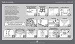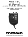
1
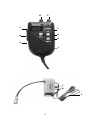
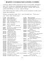
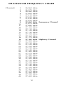
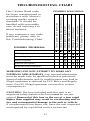
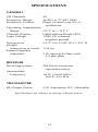
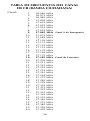
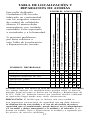
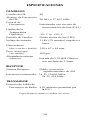
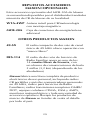
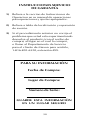
MCB-10A
40 Channel
Micro Mobile CB Radio
OWNER'S MANUAL
English/Spanish
TABLE OF CONTENTS
Product Description
1
FCC Statement
1
Performance Features
Package Contents
2
3
Controls and Functions
4
Installation Instructions
Mechanical Mounting
DC Power Supply Connection
Connecting the Power Cord
Antenna Installation
Antenna Tuning
6
6
7
7
8
9
Operating Instructions
10
Radio Communication Codes
11
CB Channel Frequency Chart
12
Troubleshooting Chart
13
Specifications
14
Optional/Replacement Accessories
15
Other Maxon Products
15
Warranty Service Instructions
16
Warranty Statement
17
Before operating your Maxon Citizens Band Radio,
read this Owner's Manual carefully. If you have a
problem, refer to the Troubleshooting Chart in this
manual before returning your radio for repairs.
TABLA DE CONTENIDO
Controles y Funciones
4
Descripción del Producto
18
Regulaciones de la FCC
(Comisión Federal de Comunicaciones)
18
Características de Funcionamiento
19
Contenido del Paquete
20
Instrucciones Para Instalación
21
21
22
Montaje Mecánico
Conexión de Alimentación Eléctrica de CC
Cómo Conectar el Cordón Eléctrico del
MCB-10A
Instalación de la Antena
La Sintonización de la Antena
22
23
24
Instrucciones de Operación
25
Tabla de Frecuencia del Canal de CB
(Banda Ciudadana)
26
Tabla de Localización y Reparación
de Averías
27
Especificaciones
28
Repuestos Accesorios Maxon/Opcionales 29
Otros Productos Maxon
29
Instrucciones Servicio de Garantía
30
Aclaración de la Garantía
31
Antes de hacer funcionar su radio de Banda Ciudadana
de Maxon lea detenidamente este Manual del
Propietario. Si tiene unproblema, refiérase a la sección
"Localización y Reparación de Averías" de este manual
antes de devolver su radio para la reparación.
PRODUCT DESCRIPTION
Thank you for choosing the Maxon
MCB-10A Micro Mobile CB Radio.
This compact, self-contained transceiver provides
many automatic features to enhance voice clarity
and sound quality.
40 Operating channels, direct access to Emergency
Channel 9 and soft touch channel selection buttons
provide convenience to the user. A unique quick
disconnect on the radio's power cord allows the
transceiver to be easily disconnected and moved
to another vehicle or stored for safety.
Enjoy your new CB!
YOU DO NOT NEED AN FCC LICENSE TO
OPERATE THIS RADIO IN THE UNITED STATES.
However, you must know and be familiar with
Part 95 of the FCC Rules in regard to Subpart D
of the Citizens Band Radio Service. (A copy is
enclosed with the unit.)
1
PERFORMANCE FEATURES
• All controls contained in compact, lightweight
handset
• Quick disconnect feature allows removal of
transceiver for storage or theft prevention
• Additional power/antenna connector boxes
can be purchased separately, allowing a single
MCB-10A transceiver to be used in multiple
vehicles
• Operates with maximum legal RF output power
(4 Watts)
• Communication range of up to 7 miles*
• Direct access to Emergency Channel 9
• Last channel memory recalls last channel
displayed
• Soft touch channel selection buttons
• Easy-to-read LED channel display
• Red transmit (TX) LED indicator lights during
active transmissions
• Top-mounted volume and squelch control knobs
• Built-in Automatic Gain Control (AGC) and
Automatic Noise Limiter (ANL) provide constant
sound level (from weak or strong signals) and
clear reception
• Automatic modulation control eliminates "peak"
and "valley" transmission signals
* Range will vary, depending on type of antenna used and
geography of surroundings.
2
PACKAGE CONTENTS
Main CB unit
Power/antenna connector box with antenna jack,
external speaker jack and fused DC power cord
Transceiver mounting bracket and installation
hardware
Owner's Manual
Copy of FCC Part 95, Subpart "D"
(Mobile CB antenna required for use, not included)
3
CONTROLS AND FUNCTIONS
A.
Built-in Electret Condenser Microphone - Transmits
voice signals during CB operation • Micrófono
Condensador Electret Incorporado - Transmite señales
de voz durante la operación del CB
B.
Push-To-Talk Bar - Permits radio transmissions • Barra
"Presione Para Hablar" (P-T-T) - Permite la transmisión
por radio
C.
LED Channel Display - Identifies selected channel
• LED Imagen de Canal - Identifica el canal CB
D.
Squelch Control - Reduces or removes background
noise when no signal is present on the channel • Control
Para Amortiguar Ruidos - Reduce o elimina el ruido de
fondo cuando no hay una señal presente en el canal
E.
Off/On-Volume Control - Turns the radio on or off and
adjusts the listening volume • Control de Volumen - Se
usa para encender o apagar el radio y para ajustar el
volumen
F.
Transmit (TX) LED Indicator - Identifies active
transmissions • Indicador LED de Transmisión
(TX) - Identifica transmisiones activas
G.
Channel Up/Down Buttons - Selects any one of the 40
available channels • Botones de Canal Arriba/Abajo Seleccionan cualquiera de los 40 canales disponibles
H.
Emergency Channel 9 Button - Provides direct access
to Emergency Channel 9 • Botón de Canal 9 de
Emergencia - Provee acceso directo al Canal 9 de
Emergencia
I.
Speaker - Broadcasts incoming signals • Altavoz - Emite
señales entrantes
J.
Antenna Jack - Provides connection for 50 Ohm mobile
CB antenna • Conector Para Antena - Provee conexión
para antena de CB móvil de 50 Ohm
K.
External Speaker Jack - Provides connection for an
optional external speaker • Conector Para Altoparlante
Externo - Provee conexión para un altavoz externo
opcional
L.
Fused 12V DC Power Cord - Provides power to radio
when wired to a vehicle's 12V DC electrical system
• Cordón Eléctrico de 12 V CC con Fusible - Provee
energía al radio cuando está conectado al sistema eléctrico
de 12 V CC de un vehículo
4
D
E
C
F
G
B
H
A
I
J
K
L
5
INSTALLATION INSTRUCTIONS
Mechanical Mounting
CAUTION: Be sure the unit is mounted where it
will not interfere with the driver or impair access
to any controls necessary for the safe driving of
the vehicle. The radio's power and/or antenna
connecting cables must be routed and secured so
that they do not interfere with the operation of the
brake, accelerator or other controls. Interference
from either the CB unit or its connecting cables
may contribute to the loss of control of the vehicle.
1) Use the power/antenna connector box as a
template for marking the location of screw
holes (self-tapping screws provided).
2) Drill the necessary holes and secure the
power/antenna connector box with the
self-tapping screws.
NOTE: EXTREME CARE SHOULD BE EXERCISED
WHEN DRILLING UP INTO THE DASH to avoid
damage to in-dash electronic ignition wiring, air
bag or air bag sensors, cruise control, instruments
or accessory wiring.
3) If you choose to mount the power/antenna
connector box under the vehicle seat or at an
alternate location where self-tapping screws
cannot be used, determine the most secure
method of fastening the power/antenna
connector box. Use strong mounting tape,
plastic tie wraps, etc.
4) Use the three included screws to mount the
transceiver hanger bracket onto the vehicle's
dash.
6
5) To connect an optional external speaker, locate
the external speaker jack on the power/antenna
connector box and firmly insert the speaker
plug into the jack. The radio speaker will be
disconnected when the external speaker is
engaged.
DC Power Supply Connection
The MCB-10A is designed for 12V DC operation
in vehicles with NEGATIVE (-) electrical systems.
Most domestic and foreign-made vehicles use a
negative ground system.
NOTE: Check your vehicle's ground requirements
before you begin radio installation. If the battery
terminal marked negative (-) is connected to the
motor block of your vehicle, it is a negative ground
system.
CAUTION: DO NOT attempt to connect the
MCB-10A to a positive (+) ground vehicle. Doing
so may cause damage to the CB unit and to your
vehicle's electrical system.
Connecting the MCB-10A Power Cord
1) Make sure the off/on-volume control is in the
off position before proceeding.
2) Remove the fuse located in the MCB-10A DC
power cord. To do this, grasp each end of the
white fuse casing, push together and twist the
ends away from one another.
3) Connect the red lead wire of the DC power
cord to a positive (+) 12V DC source, either
the engine fuse block, the internal fuse box, or
directly to the positive (+) post of your battery.
7
Usually the internal fuse box is the most
convenient connecting point. You may wish
to connect the red lead wire to the accessory
terminal on the engine fuse block or in the
ignition switch so your CB radio will automatically turn off when the ignition is disengaged,
preventing any accidental battery drainage.
4) Connect the black lead wire to the metal
chassis of the vehicle. For the best connection,
remove any paint from the grounding point. A
good, direct metal-to-metal ground is essential
for best performance.
5) Replace the fuse into the white casing on the
MCB-10A DC power cord.
Antenna Installation
Your Maxon MCB-10A requires a mobile mount
antenna for operation. Because of varying vehicle
applications, individual needs and owner cost
preferences, an antenna is not included with
your MCB-10A.
Maxon's model WTA-4WP mobile mount antenna
may be obtained from a local Maxon CB distributor,
or you may use any standard 50 Ohm mobile mount
CB antenna with a PL-259 connector.
NOTE: Please carefully follow the antenna manufacturer's installation instructions. Never operate
your CB radio without an antenna or with a broken
antenna cable. Doing so could cause internal
damage to the CB circuitry. Always:
• Connect the antenna securely at the antenna
receptacle of the unit.
• Mount the antenna as high on the vehicle as
8
possible - the more the antenna extends above
the roof, the better the reception will be.
• If possible, mount the antenna in the center of
the chosen surface.
• Keep the antenna cables away from noise
sources such as the ignition system, gauges, etc.
• Make sure you have a solid, metal-to-metal
ground.
Antenna Tuning
Most antennas are factory tuned. However, radio
performance can usually be improved by slightly
lengthening or shortening the antenna using a
Standing Wave Ratio (SWR) meter (not included.)
Refer to the antenna manufacturer's installation
manual for the exact tuning procedure. You can
purchase an SWR meter or have your antenna
checked by your CB Dealer's service department.
9
OPERATING INSTRUCTIONS
1)
Turn the power on and adjust to a comfortable
volume level.
2)
Select any one of the 40 channels by pressing
the channel up/down buttons.
3)
Adjust the squelch control knob to reduce
any undesirable background noise. To do this,
select a channel where no signals are present
or wait until signals cease on your channel.
Then, rotate the squelch control knob clockwise to a point where the background noise
ceases.
When the squelch is set properly, the speaker will
remain quiet until a signal is received. Do not set
the squelch too high, or you will not be able to
receive weaker signals.
To Transmit: Hold the transceiver microphone area
2-3 inches from your mouth and press the push-totalk (P-T-T) bar located on the side of the transceiver.
Speak into the microphone slowly and in a normal
tone of voice. When transmitting, the TX LED will
glow.
To Receive: Release the push-to-talk bar.
10
RADIO COMMUNICATION CODES
Citizens Band radio operators have universally adopted
the "10" Code for standard questions and answers. It
enables them to communicate faster, easier and more
understandably in noisy surroundings.
The following are some of the most common codes and
their descriptions.
When using the code 10-1, you would say, "Ten one",
not "One zero dash one".
Code
10-1
10-2
10-3
10-4
10-5
10-6
10-7
10-8
10-9
10-10
10-11
10-12
10-13
10-16
10-17
10-18
10-19
10-20
10-21
10-22
10-23
10-24
10-25
10-26
10-27
10-28
10-29
10-30
10-32
10-33
10-34
Code
Description
Description
10-35 Confidential information.
Receiving poorly.
10-36 Correct time is________.
Receiving well.
10-37 Wrecker needed at ____.
Stop transmitting.
10-38 Ambulance needed at__.
OK, message received.
10-39 Your message delivered.
Relay message.
10-41 Please turn to channel_.
Busy, stand by.
10-42 Traffic accident at______.
Out of service; leaving
10-43 Traffic tie-up at________.
the air.
10-44 I have a message for you.
In service, subject to call.
10-45 All units within range
Repeat message.
report.
Transmission completed,
10-50 Break channel.
standing by.
10-60 What is next message
Talking too fast.
number?
Visitors present.
10-62 Unable to copy; use phone.
Advise weather/
10-63 Network directed to.
road conditions.
10-64 Network clear.
Make pickup at_______.
10-65 Awaiting your next
Urgent business.
message/assignment.
Anything for us?
10-67 All units comply.
Nothing for you;
10-70 Fire at _______________.
return to base.
10-71 Proceed with transmission
My location is_______.
in sequence.
Call by telephone.
Report in person to_____. 10-77 Negative contact.
10-81 Reserve hotel room at___.
Stand by.
Completed last assignment. 10-82 Reserve room for_______.
10-84 My telephone number is_.
Can you contact?
Disregard last information. 10-85 My address is_________.
10-91 Talk closer to microphone.
I am moving to channel_.
10-93 Check my frequency on
Identify your station.
this channel.
Time is up for contact.
10-94 Please give me a long
Does not conform
count.
to FCC rules.
I will give you a radio check.10-99 Mission completed; all
units secure.
Emergency traffic.
10-200 Police needed at_______.
Trouble at this station.
11
CB CHANNEL FREQUENCY CHART
Channel:
1
2
3
4
5
6
7
8
9
10
11
12
13
14
15
16
17
18
19
20
21
22
23
24
25
26
27
28
29
30
31
32
33
34
35
36
37
38
39
40
26.965
26.975
26.985
27.005
27.015
27.025
27.035
27.055
27.065
27.075
27.085
27.105
27.115
27.125
27.135
27.155
27.165
27.175
27.185
27.205
27.215
27.225
27.255
27.235
27.245
27.265
27.275
27.285
27.295
27.305
27.315
27.325
27.335
27.345
27.355
27.365
27.375
27.385
27.395
27.405
12
MHz
MHz
MHz
MHz
MHz
MHz
MHz
MHz
MHz Emergency Channel
MHz
MHz
MHz
MHz
MHz
MHz
MHz
MHz
MHz
MHz Highway Channel
MHz
MHz
MHz
MHz
MHz
MHz
MHz
MHz
MHz
MHz
MHz
MHz
MHz
MHz
MHz
MHz
MHz
MHz
MHz
MHz
MHz
TROUBLESHOOTING CHART
If you experience any radio
problems, please refer to
this Troubleshooting Chart.
POSSIBLE PROBLEMS:
Check power cable connection
Check in-line and main junction fuses
Check squelch adjustment
Check off/on-volume control
Change to active channel
Check antenna connection
Fully depress push-to-talk bar
POSSIBLE SOLUTIONS:
This Citizens Band radio
has been manufactured in
accordance with Maxon's
exacting quality control
standards. It should be
handled with reasonable
care. Avoid exposing it to
dirt or moisture.
No sound or display
LED lights, but no sound
No voice reception
Poor reception
Unclear reception
Transmission problems
WARNING: DO NOT ATTEMPT TO MAKE ANY
INTERNAL ADJUSTMENTS. Any internal adjustments
must be made only by qualified technical personnel.
Internal adjustments and /or modifications can lead to
illegal operation as defined by FCC Rules and Regulations, Part 95. Illegal operation can result in serious
consequences.
CAUTION: The fuse included with this unit is an
important safety feature which must not be circumvented. Removal of this fuse or the use of a fuse rated
higher than supplied may result in overheating and/or
fire and consequential damage to the unit or vehicle.
If a replacement fuse burns out, have the unit inspected
and repaired by a qualified service technician.
13
SPECIFICATIONS
GENERAL
CB Channels:
Frequency Range:
Frequency Control:
40
26.965 to 27.405 MHz
Phase Locked Loop (P-L-L)
synthesizer
Operating Temperature
Range:
-22o F to +122o F
Channel Display:
Light Emitting Diode (LED)
Input Voltage:
13.8V DC nominal,
negative ground
Dimensions:
5-1/2" H x 2-5/8" W x 1-3/4" D
Weight
(transceiver w/cord): 12.8 oz.
External Speaker
(optional):
5 W input @ 8 Ohms with
3.5 mm plug
RECEIVER
Receiving System:
Intermediate
Frequency:
AM Dual conversion
superheterodyne
1st IF: 10.695 MHz
2nd IF: 455 kHz
TRANSMITTER
RF Output Power:
4 W (Maximum FCC allowable)
Specifications are subject to change without notice.
14
OPTIONAL / REPLACEMENT
MAXON ACCESSORIES
These Maxon MCB-10A accessories are available
from your local Maxon CB distributor/retailer.
WTA-4WP
Magnetic mount mobile
CB/weather antenna
MCB-20A
Additional power/antenna
connector box
OTHER MAXON PRODUCTS
49-SX
Compact, single channel 49 MHz
two-way radio offers "hands free"
operation
FRS-114
Two-way Family Radio Service radio
operates on one of 14 license-free
channels, provides up to 2-mile range
of communications (depending on
surroundings)
Maxon manufactures a full line of personal
electronic products, including handheld and
mobile CB radios, 49 MHz personal communicators, Family Radio Service radios, GMRS/DOT
two-way radios, CDMA, GSM and AMPS cellular
handsets, weather monitors and a variety of
optional accessory items. Look for Maxon brand
products in quality retail stores nationwide.
15
WARRANTY SERVICE INSTRUCTIONS
1) Refer to the Operating Instructions section of
this Owner’s Manual for proper operation and
adjustments.
2) Refer to the basic Troubleshooting Chart for
possible solutions.
3) If the problem cannot be corrected by reference to this Owner's Manual, return the
product with proof of purchase (a sales receipt)
to the place of purchase, or call Maxon’s
Customer Service Department for assistance,
1-800-821-7848, Ext. 499.
FOR YOUR RECORDS
Purchase Date:
Purchased From:
Serial Number:
KEEP THIS INFORMATION
IN A SAFE PLACE.
16
LIMITED WARRANTY
The Consumer Products Division of Maxon America, Inc., (hereinafter referred to as "Maxon"), warrants that its Products and their
included accessories will be free from defects in workmanship or
materials under normal use for a period of one (1) year from date
of purchase by the original end user, provided that the buyer has
complied with the requirements stated herein.
If the Product fails to function under normal use because of
manufacturing defect(s) or workmanship during the one (1)
year period following the date of purchase, it will be replaced
or repaired at Maxon's option at no charge when returned to
the place of purchase. The defective unit must be accompanied
by proof of the date of purchase in the form of a sales receipt.
Maxon's sole obligation hereunder shall be to replace or repair
the product covered in this Warranty. Replacement, at Maxon's
option, may include a similar or higher-featured product. Repair
may include the replacement of parts or boards with functionally
equivalent reconditioned or new parts or boards. Replaced parts,
accessories, batteries or boards are warranted for the balance of
the original time period. All replaced parts, accessories, batteries
or boards become the property of Maxon America, Inc.
Maxon shall have no obligation to make repairs or to cause
replacement required which result from normal wear and tear
or necessitated in whole or in part by catastrophe, the fault or
negligence of the user, improper or unauthorized alterations,
repairs to the Product, incorrect wiring, use of the Product in
a manner for which it was not designed, or by causes external
to the Product. This warranty is void if the serial number is
altered, defaced or removed.
The purchaser shall provide for removal of the defective Product
and installation of its replacement.
THE EXPRESS WARRANTIES CONTAINED HEREIN ARE IN LIEU
OF ALL OTHER WARRANTIES, EITHER EXPRESSED OR IMPLIED
OR STATUTORY, INCLUDING, WITHOUT LIMITATION, ANY
WARRANTY OF MERCHANTABILITY OR FITNESS FOR A
PARTICULAR PURPOSE.
FOR ANY PRODUCT WHICH DOES NOT COMPLY WITH THE
WARRANTY SPECIFIED, THE SOLE REMEDY WILL BE REPAIR
OR REPLACEMENT. IN NO EVENT WILL MAXON AMERICA, INC.
BE LIABLE TO THE BUYER OR ITS CUSTOMERS FOR ANY
DAMAGES, INCLUDING ANY SPECIAL, INCIDENTAL, INDIRECT
OR CONSEQUENTIAL DAMAGES, OR THE LOSS OF PROFIT,
REVENUE OR DATA ARISING OUT OF THE USE OF OR THE
INABILITY TO USE THE PRODUCT.
This warranty is void for sales and deliveries outside of the U.S.A.
17
DESCRIPCIÓN DEL PRODUCTO
Gracias por seleccionar el CB Radio
Maxon MCB-10A Micro Mobile.
Este transceptor compacto y autónomo provee
muchos dispositivos automáticos para realzar la
claridad de voz y la calidad de sonido.
Los 40 canales de operación, el acceso directo al
Canal 9 de Emergencia y los botones de selección
de canal de tacto suave proporcionan conveniencia
al usuario. Un sistema exclusivo de desconexión
rápida de los cordones eléctricos del radio permite
que el transceptor sea fácilmente desconectado y
trasladado a otro vehículo o guardado por razones
de seguridad.
¡ Disfrute su nuevo Maxon CB !
NO NECESITA UNA LICENCIA DE LA FCC
PARA HACER FUNCIONAR ESTE RADIO EN
LOS ESTADOS UNIDOS. Sin embargo, debe
conocer y estar familiarizado con la Parte 95
de las Reglas de la FCC en relación con la
Subparte D del Servicio de Radio de Banda
Ciudadana. (Con la unidad se anexa una copia).
18
CARACTERISTÍCAS DE
FUNCIONAMIENTO
• Todos los controles están contenidos en un
micrófono manual (handset) compacto y liviano
• El dispositivo de desconexión rápida permite
quitar el transceptor para guardarlo o prevenir robos
• Pueden comprarse por separado cajas de conectores
para energía/antena, permitiendo así el uso de un
mismo transceptor MCB-10A en múltiples
vehículos
• Opera con el máximo de potencia de salida de RF
legal (4 Vatios)
• Alcance de comunicación de hasta 7 millas
(11 km)*
• Acceso directo al Canal 9 de Emergencia
• Memoria de último canal recuerda último canal
mostrado
• Botones de selección de canal de tacto suave
• Pantalla LED de canales fácil de leer
• Luces LED rojas indicadoras de transmisión (TX)
durante transmisiones activas
• Perillas de control de volumen y squelch montadas
en la parte superior
• El Control de Ganancia Automático (AGC)
y el Limitador de Ruido Automático (ANL)
incorporados, proveen nivel de sonido constante
(para señales débiles o fuertes) y recepción clara
• Control automático de modulación elimina señales
de transmisión de "pico" y "valle"
* El alcance puede variar, dependiendo del tipo de antena usado
y la geografía de los alrededores.
19
CONTENIDO DEL PAQUETE
Unidad principal CB
Caja de conectores para energía/antena con jack
de antena, jack de altavoz externo y cordón
eléctrico de CC con fusible
Soporte de montaje para el transceptor y elementos
fijadores para su instalación
Manual del dueño
Copia de la Parte 95 de la FCC, Subparte "D"
(No se incluye la antena requerida para CB móvil)
20
INSTRUCCIONES PARA INSTALACIÓN
Montaje Mecánico
PRECAUCIÓN: Asegúrese que la unidad está
montada donde no interfiera con el conductor o
estorbe el acceso a cualquier control necesario
para conducir el vehículo con toda seguridad.
Los cables de conexión de alimentación de
energía eléctrica y/o de antena del radio deben
ser conducidos y asegurados de manera que no
interfieran con la operación del freno, acelerador
u otros controles. La interferencia por parte de la
unidad CB o sus cables conectores, podrían ontribuir
a la pérdida del control del vehículo.
1) Use la caja de conectores de energía/antena
como plantilla para hacer los agujeros de
ubicación (se proveen tornillos autorroscantes).
2) Taladre los agujeros necesarios y asegure el
caja de conectores de energía/antena con los
tornillos autorroscantes.
NOTA: SE DEBERÁ TENER CUIDADO ESPECIAL
AL TALADRAR EL TABLERO para evitar daños al
alambrado dentro del panel de instrumentos, para
encendido electrónico, bolsa de aire o sensores de
bolsa de aire, control de crucero, instrumentos o
alambrados para accesorios.
3) Si usted escoge montar la caja de conectores de
energía /antena debajo del asiento del vehículo
o en una ubicación alternativa donde no puedan
utilizarse tornillos autorroscantes, determine la
forma más segura de fijar la caja de conectores
de energía/antena. Utilice cinta fuerte de
montaje, bandas fijadoras de plástico, etc.
4) Use los tres tornillos incluidos para montar el
soporte colgante del transceptor en el panel
de instrumentos del vehículo.
21
5) Para conectar un altavoz externo opcional,
ubique el jack del altavoz externo en la caja
de conectores de energía/antena e inserte
firmemente el enchufe del altavoz en el jack.
El altavoz del radio quedará desconectado
cuando esté activado el altavoz externo.
Conexión de Alimentación Eléctrica de CC
El MCB-10A está diseñado para trabajar con 12V CD
en vehículos con sistemas eléctricos de NEGATIVO
(-) A TIERRA. La mayoría de los vehículos y camiones
domésticos e importados, usan el sistema negativo a
tierra.
NOTA: Verifique los requerimientos de conexión
a tierra del vehículo antes de comenzar la
instalación del radio. Si el terminal negativo (-)
de su batería está conectado al bloque del motor,
su vehículo tiene un sistema negativo a tierra.
PRECAUCIÓN: No intente conectar su MCB-10A
a un vehículo con sistema (+) POSITIVO a tierra
puesto que podría dañar su unidad CB y/o el
sistema eléctrico de su vehículo.
Cómo Conectar el Cordón Eléctrico del MCB-10A
1) Asegúrese que el control de prendido/apagadovolumen esté en la posición de apagado antes
de continuar.
2) Retire el fusible ubicado en el cordón eléctrico
de CC del MCB-10A. Para esto, agarre cada
extremo de la caja blanca del fusible, empuje
hacia adentro y gire los extremos hacia afuera
uno del otro.
3) Conecte el alambre rojo del cable energético
de CD a una fuente positiva (+) de 12V de
corriente directa - bien sea del bloque de
fusibles del motor, la caja interna de fusibles,
22
o directamente al terminal positivo (+) de
su batería. Generalmente, la caja interna de
fusibles resulta el punto de conexión más
conveniente. Usted podría optar por conectar
el alambre rojo al terminal para accesorios de
la caja de fusibles del motor, o en el interruptor
del arranque, de manera que su CB se
desactive automáticamente cuando usted
apaga su ignición. De esta forma se evitará el
agotamiento accidental de la batería.
4) Conecte el alambre negro al chasis metálico
del vehículo. Para la mejor conexión, elimine
toda pintura que se encuentre en el punto de
puesta a tierra. Para un desempeño óptimo, es
esencial un contacto directo, metal-a-metal con
la tierra.
5) Reponga el fusible en la caja blanca en el
cordón eléctrico de CC del MCB-10A.
Instalación de la Antena
Su Maxon MCB-10A para su operación, requiere
una antena de CB instalada en el vehículo. La
antena no está incluida con su MCB-10A debido a
las distintas aplicaciones en vehículos, necesidades
individuales y preferencias económicas del
propietario.
Usted podrá usar cualquier sistema de antena
estándar de 50 Ohmios para uso en CB, para montaje
en vehículos con un conector PL-259. El modelo de
antena Maxon WTA-4WP se puede obtener de su
distribuidor/detallista local de productos Maxon CB.
NOTA: Por favor observe cuidadosamente las
instrucciones de instalación del fabricante de la
antena. Nunca opere su radio CB sin una antena o
con un cable de antena roto. Si se hace esto pueden
23
ocasionarse daños internos al circuito del CB.
Siempre:
• Conecte la antena con toda seguridad al
•
•
•
•
receptáculo para antena que tiene la unidad
Monte la antena en el vehículo tan alto como
sea posible - cuanto más se prolongue la
antena por encima del techo del vehículo,
mejor será la recepción
De ser posible, instale la antena en el centro
de la superficie que se haya seleccionado
Mantenga los cables de la antena alejados de
fuentes de ruidos tales como el sistema de
encendido, instrumentos, etc.
Cerciórese de que se dispone de una tierra
sólida con contacto de metal-a-metal
La Sintonización de la Antena
La mayoría de las antenas están sintonizadas en
fábrica, pero su rendimiento puede, generalmente,
mejorarse mediante una ligera modificación
alargando o acortando la antena mediante el uso
del (SWR), medidor de ondas estacionarias (no
está incluido). Refiérase al manual de instalación
del fabricante de la antena. Usted puede adquirir
un SWR [medidor de ondas estacionarias], o pedir
al departamento de servicio de su distribuidor de
CB que compruebe su antena.
24
INSTRUCCIONES DE OPERACIÓN
1)
Conecte la energía eléctrica y ajuste a un nivel
de volumen confortable.
2)
Seleccione cualquiera de los 40 canales
oprimiendo los botones de canal arriba/abajo.
3)
Ajuste el botón de control de amortiguamiento
de ruidos para reducir cualquier ruido de fondo
indeseable cuando no se reciba una señal. Para
hacer esto, seleccione un canal que no tenga
señal, o espere que la señal cese en su propio
canal. Después mueva hacia la derecha el
botón de control de amortiguamiento de ruidos
hasta el punto en que cese el ruido de fondo.
Cuando el amortiguamiento de ruidos está
correctamente ajustado, el altoparlante permanecerá
tranquilo hasta recibir una señal. Para poder recibir
señales débiles, no ponga demasiado alto el
amortiguador de ruidos.
Para Transmitir: Sostenga el área del micrófono del
transceptor 2 a 3 pulgadas (5 a 8 cm) de su boca y
oprima la barra empuje-para-hablar (P-T-T) ubicada
al costado del transceptor. Hable al micrófono con
entitud y tono de voz normal. Al transmitir se
luminará el LED de TX.
Para recibir: Suelte la barra de empujar-para-hablar.
25
TABLA DE FRECUENCIA DEL CANAL
DE CB (BANDA CIUDADANA)
Canal:
1
2
3
4
5
6
7
8
9
10
11
12
13
14
15
16
17
18
19
20
21
22
23
24
25
26
27
28
29
30
31
32
33
34
35
36
37
38
39
40
26.965
26.975
26.985
27.005
27.015
27.025
27.035
27.055
27.065
27.075
27.085
27.105
27.115
27.125
27.135
27.155
27.165
27.175
27.185
27.205
27.215
27.225
27.255
27.235
27.245
27.265
27.275
27.285
27.295
27.305
27.315
27.325
27.335
27.345
27.355
27.365
27.375
27.385
27.395
27.405
MHz
MHz
MHz
MHz
MHz
MHz
MHz
MHz
MHz Canal 9 de Emergencia
MHz
MHz
MHz
MHz
MHz
MHz
MHz
MHz
MHz
MHz Canal de Carretera
MHz
MHz
MHz
MHz
MHz
MHz
MHz
MHz
MHz
MHz
MHz
MHz
MHz
MHz
MHz
MHz
MHz
MHz
MHz
MHz
MHz
26
TABLA DE LOCALIZACIÓN Y
REPARACION DE AVERÍAS
Verifique la conexión de la antena
Oprima totalmente la barra de empuje-para-hablar cuando esté hablando
Cambie al canal activo
POSIBLES PROBLEMAS:
Verifique el ajuste del silenciador
Verifique el control de encendido/apagado de potencia-volumen
Si presenta problemas,
por favor refiérase a
esta Tabla de Localización
y Reparación de Averías.
Compruebe los fusibles (en línea y bloque de conexión principal)
POSIBLES SOLUCIONES:
Compruebe la conexión del cable energético
Este radio de Banda
Ciudadana (CB) ha sido
fabricado en conformidad
con las exigentes normas
de control de calidad de
Maxon. El mismo debe
manipularse con cuidado
razonable. Evite exponerlo
a suciedades y a la humedad.
No hay sonido ni pantalla
LED ilumina, pero sin sonido
Ninguna recepción de voz
Recepción pobre
Recepción borrosa
Problemas de transmisión
ADVERTENCIA: NO INTENTE HACER NINGUN AJUSTE INTERNO.
Los ajustes internos y/o modificaciones pueden llevar al funcionamiento ilegal tal como se define por las Reglas y Regulaciones de
la FCC, Parte 95. Deberán hacerse por personal técnico calificado.
La operación ilegal puede traer serias consecuencias.
PRECAUCIÓN: El fusible que se incluye con esta unidad es
una importante característica de seguridad que no debe burlarse.
La eliminación de este fusible o el uso de un fusible de mayor
capacidad que el suministrado, puede derivar en el calentamiento
y/o incendio y daños emergentes a la unidad y al vehículo. Si se
quema un fusible, lleve a inspeccionar la unidad y a repararla por
un técnico de servicio calificado.
27
ESPECIFICACIONES
GENERALES
Canales de CB:
40
Alcance de Frecuencia
de CB:
26.965 a 27.405 MHz
Control de
Frecuencia:
Sintetizador con circuito de
sincronización de fase (P-L-L)
Límites de la
Temperatura
Operativa:
-30o C to +50o C
Pantalla de Canales:
Diodo emisor de luz (LED)
Voltaje de entrada:
13.8V CD nominal, negativo a
tierra
Dimensiones
(alto x ancho x hondo): 140 x 67 x 44 mm
Peso (transceptor
con cordón):
360 gm.
Altoparlante externo
(optativo):
Entrada de 5 W @ 8 Ohmios
con enchufe de 3.5mm
RECEPTOR
Sistema Receptor:
Doble conversión
superheterodina de AM
Frecuencia intermedia: 1a. FI: 10.695 MHz
2a. FI: 455 MHz
TRANSMISOR
Potencia de Salida de
Frecuencia de Radio: 4 W (máximo permitido por
la FCC)
Especifications sujetas a cambio sin avisos.
28
REPUESTOS ACCESORIOS
MAXON/OPCIONALES
Estos accesorios opcionales del MCB-10A de Maxon
se encuentran disponibles por el distribuidor/vendedor
minorista de CB de Maxon de su localidad.
WTA-4WP Antena móvil para CB/meteorología
con montaje magnético
MCB-20A
Caja de conectores de energía/antena
adicional
OTROS PRODUCTOS MAXON
49-SX
El radio compacto de dos vías de canal
único de 49 MHz ofrece operación con
“manos libres”
FRS-114
El radio de dos vías de Servicio de
Radio Familiar opera en uno de los
14 canales libres de licencia, con
un alcance de comunicaciones de hasta
2 millas (3,2 km) (dependiendo de los
alrededores)
Maxon fabrica una línea completa de productos
electrónicos de uso personal, incluyendo radios
CB portátiles y móviles,comunicadores personales
en 49 MHz, radios para Servicios de Radio
Familiares, radios transmisores-receptores GMRS/
DOT, equipos celulares CDMA, GSM y AMPS,
monitores meteorológicos y toda una variedad de
accesorios optativos. Busque los productos de
marcas de Maxon en tiendas de venta al detalle
por todo el país.
29
INSTRUCCIONES SERVICIO
DE GARANTÍA
1) Refiera a la seccíon de Instrucciones de
Operacion en su manual de operaciones
para operaciones y ajustes apropiados.
2) Refiera a tabla de localización y reparación
de averías.
3) Si el procedimiento anterior no corrije el
problema que usted esta experimentando
devuelva el producto (con el recibo de
compra) al lugar en el cual lo compró,
o llame al Departamento de Servicio
para el cliente de Maxon para asistirle,
1-816-891-6320, extensión 499.
PARA SU INFORMACIÓN
Fecha de Compra:
Lugar de Compra:
Numero de Serie:
GUARDE ESTA INFORMACIÓN
EN UN LUGAR SEGURO
30
ACLARACIÓN DE LA GARANTÍA
LIMITADA
La División de Productos para el Consumidor de Maxon
America, Inc. (de aquí en adelante referido como "Maxon"),
garantiza que sus Productos y los accesorios incluidos estarán
libres de defectos de mano de obra o materiales bajo un uso
normal por un período de un (1) año partir de la fecha de
compra por el usuario original, siempre y cuando el comprador
haya cumplido con los requerimientos aquí declarados.
Si este producto no funciona bajo condiciones normales de uso
debido a defecto(s) de fabricación o mano de obra durante el
período de un (1) año después de la fecha de compra, será
reemplazado o reparado a opción de Maxon sin cargos, una
vez retornado al lugar de compra. La unidad defectuosa tiene
que estar acompañada de una prueba de la fecha de compra
en forma de un recibo de compra.
Maxon no tendrá obligación alguna de hacer reparaciones ni
ningún reemplazo que se requiera debido al desgaste normal
o que se necesite total o parcialmente debido a una catástrofe,
falta o negligencia del usuario, alteraciones impropias o no
autorizadas, reparaciones hechas al Producto, cableado
incorrecto, uso del Producto de una manera para la cual no
fue diseñado, o por causas externas al Producto. Esta garantía
es nula si se altera, borra, o remueve el número de serie.
El comprador deberá hacerse responsable de remover el
Producto defectuoso e instalación de su repuesto.
LAS GARANTÍAS EXPRESAS AQUI CONTENIDAS
SUSTITUYEN TODAS LA OTRAS GARANTÍAS, YA SEAN
EXPRESAS, O IMPLICITAS, O ESTATUTARIAS, INCLUYENDO,
SIN LIMITACION, CUALQUIER GARANTIA DE BUENA
CALIDAD O IDONEIDAD PARA UN PROPOSITO
PARTICULAR.
PARA CUALQUIER PRODUCTO QUE NO CUMPLA CON
LA GARANTIA ESPECIFICADA, EL UNICO REMEDIO SERA
LA REPARACION O REEMPLAZO. MAXON AMERICA, INC.
EN NINGÚN CASO SERÁ RESPONSABLE AL COMPRADOR
O A SUS CLIENTES POR NINGÚN DAÑO, INCLUYENDO
DAÑOS ESPECIALES, INCIDENTALES, INDIRECTOS O
CONSECUENTES, NI POR LA PÉRDIDA DE GANANCIAS,
INGRESOS O DATOS QUE SURJA DEL USO O LA
INHABILIDAD DE USAR ESTE PRODUCTO.
Esta garantía es nula para ventas y envíos fuera de los Estados
Unidos.
31
Thank you for choosing Maxon!
¡Gracias por escoger a Maxon!
For more information, contact:
Para obtener más información,
comuníquese con:
Maxon America, Inc.
Consumer Products Division
10828 NW Air World Drive
Kansas City, Missouri 64153
(Within USA) Phone: 1-800-821-7848, Ext. 399
(Outside USA) Phone: 1-816-891-6320, Ext. 399
Fax: 816/891-8815
Printed in Thailand
Impreso en Tailandia
U.S. P/N: 680-090-0040 Rev. A