1
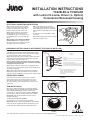
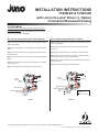
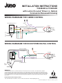
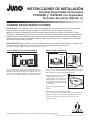
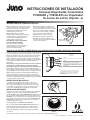
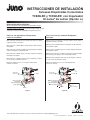
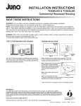
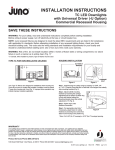
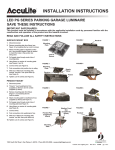
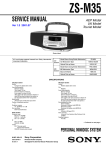
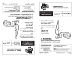
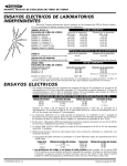
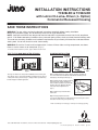
INSTALLATION INSTRUCTIONS
TC920LED & TC922LED
with Lutron Hi-Lume® Driver (-L Option)
Commercial Recessed Housing
SAVE THESE INSTRUCTIONS
WARNING: For your safety, read and understand instructions completely before starting installation.
Before wiring to power supply, turn off electricity at the fuse or circuit breaker box.
NOTE: Juno recessed fixtures are designed to meet the latest NEC requirements and are listed in full compliance
with UL 1598. Before attempting installation of any recessed lighting fixture, check your local electrical building code.
This code sets the wiring standards and installation requirements for your locality and should be understood before
starting work. Use of non-Juno trims voids Juno warranty.
WARNING: Risk of fire. Do not install insulation within 3 inches of fixture sides or wiring compartment, nor above
fixture in such a manner as to entrap heat. (Fig. 1)*
* In Canada, when insulation is present, Type IC fixtures must be used.
TYPE TC FOR NON-INSULATED CEILINGS
HOUSING INSTALLATION
BUTTERFLY
BRACKET
3"
Figure 1
Juno Type TC fixtures are designed for installations where housing and
J-box will not come in contact with insulation. Insulation must be spaced
3” away from housing and J-box (Fig. 1). Improper fixture operation may
indicate improper insulation application.
Figure 2
Figure 3
CARRIAGE
BOLT
Step 1. Install housing into ceiling cavity by inserting 1/2” EMT, 3/4”
or 1-1/2” C-Channel, linear flat bars or Real Nail 3 bar hangers into
butterfly style mounting brackets (Fig. 2).
Step 2. Adjust butterfly mounting brackets
by loosening the carriage adjustment
bolt so bottom of plaster ring is flush with
finished ceiling line. Mounting brackets
have total vertical adjustment of 3”
(Fig. 3).
Step 3. Follow steps under Electrical
Connection.
Hex Screws
Figure 4
Step 4. Cut appropriate sized hole.*
If necessary, adjust fixture for ceiling thickness by loosening hex screws
that attach round housing to the plaster ring.
* Note: Cut 5-5/8” (for 5” housings) or 6-7/8” (for 6” housings) opening.
1300 South Wolf Road • Des Plaines, IL 60018 • Phone 800-323-5068 • www.junolightinggroup.com
© 2014 Juno Lighting LLC
Rev 5/14
P3693
pg 1 of 4
INSTALLATION INSTRUCTIONS
TC920LED & TC922LED
with Lutron Hi-Lume® Driver (-L Option)
Commercial Recessed Housing
ELECTRICAL CONNECTION INSTRUCTIONS
Step 1. Provide electrical service according
to your local electrical code to the wiring box
located on the plaster frame. Supply wire
insulation must be rated for at least 90˚C.
Step 2. Remove wiring box cover. Remove
the appropriate round knock-out(s) and
accommodate the type of electrical service to
be used/allowed by your local electrical code.
(Fig. 5)
Metal Conduit (rigid or flexible)/Non-Metallic
Sheathed Cable Remove appropriate round
knock-out(s) and connect conduit to wiring box
with proper connectors (not supplied).
Step 3. Strip supply wire 3/8" and insert
each supply wire into appropriate connector.
Connect black fixture wire to hot, white fixture
wire to neutral and green fixture wire to ground.
(Fig. 5)
Knock-out
For instruction on connecting dimmer wiring,
see page 3.
Step 4. Place all wiring and connectors back in
wiring box and replace cover.
Quick
Connector
Figure 5
EMERGENCY BATTERY BACK UP WITH REMOTE TEST SWITCH (BR OPTION)
When the fixture is ordered with the emergency battery back up
option (BR), the housing comes from the factory with the battery
pack already wired to the fixture and a carton with the test switch
accessories (shipped in same carton as housing).
FIXTURE
JUNCTION BOX
SUPPLY
CONNECTIONS
Step 1. Provide electrical service according to your local electrical
code to the junction box located on the plaster ring. Supply wire
insulation must be rated for at least 90˚C.
Note: For proper charging and function of emergency battery,
an unswitched hot conductor must be connected to the battery
independant of the driver power.
WHITE
GREEN
NEUTRAL
GROUND
WHITE/RED
HOT SWITCHED FIXTURE POWER
Step 2. Remove wiring box cover. Remove the appropriate round
knock-out(s) and connect electrical supply to wiring box with proper
connectors (not supplied).
ORANGE/BLACK
HOT UNSWITCHED POWER FOR BATTERY CHARGING
NOTES:
• POWER FOR FIXTURE AND BATTERY CHARGING
MUST BE FROM THE SAME BRANCH CIRCUIT.
• REFER TO THE EMERGENCY BATTERY
INSTRUCTIONS FOR ADDITIONAL WIRING
REQUIREMENTS.
Step 3. Refer to the instruction manual provided by the battery
manufacturer located in the carton with the test accessories to
complete wiring and installation of emergency fixture and test switch.
DRIVER REPLACEMENT
Figure 6
Driver replacements must be performed by a qualified
electrician. Remove inner housing from fixture to access
driver. Order replacement kits as identified on the driver.
The replacement kits include detailed instructions for driver
replacement.
Optic
Reflector
TRIM INSTALLATION
After ceiling is finished and painted, remove paint shield from
fixture. Discard or recycle. To install trims using COIL SPRINGS
remove OPTIC REFLECTOR by rotating 1/4 turn counterclockwise (Fig. 7). Connect trim springs to fixture L-brackets
as shown (Fig. 8). Take note of flange details at top of OPTIC
REFLECTOR, align and insert in fixture and rotate 1/4 turn
clockwise until it stops.
Figure 7
Coil
Spring
L-Bracket
To install trims with TORSION SPRINGS:
For lensed trims, it is not necessary to remove OPTIC
REFLECTOR. For lensed trims equipped with an internal reflector,
remove the reflector supplied with the trim and discard or recycle.
For hyperbolic trims, follow instructions provided with the trim.
Figure 8
1300 South Wolf Road • Des Plaines, IL 60018 • Phone 800-323-5068 • www.junolightinggroup.com
© 2014 Juno Lighting LLC
Rev 5/14
P3693
pg 2 of 4
INSTALLATION INSTRUCTIONS
TC920LED & TC922LED
with Lutron Hi-Lume® Driver (-L Option)
Commercial Recessed Housing
FIXTURE DIMMING
Fixture
Ground
Lutron driver option for TC920LED, TC922LED and Chicago Plenum
and Emergency Options
Universal input voltage (120VAC thru 277VAC) housing consult Lutron
website for specific dimmer compatibility.
Lutro
BLK (-V)
RED (+V)
Coopersbu
e
Hi-lum
LED
Driver
rg, PA 1803
6
Hi-lu
For use with Lutron EcoSystem® Controls
Step 1. Properly ground fixture according to local and national electrical
codes and regulations.
Step 1. Properly ground fixture according to local and national electrical
codes and regulations.
Step 2. Connect the White wire from the LED driver to Neutral from the
dimmer.
Step 2. Connect the White wire from the LED driver to Neutral of the
power feed.
Step 3. Connect the dimmed hot (not supplied) from dimmer to orange
port on LED driver.
Step 3. Connect
the Black wire in the J-box to Hot ofV-the
power feed.
Ground
/ Black
Step 4. Connect the E1 and E2 on the EcoSystem Digital Control Bus
to the purple and gray wire port on the LED driver.
BLK (-V)
RED (+V)
e
Hi-lum
LED
Driver
Lutron Dimming Control
Gray
Coopersbu
rg, PA 1803
6
Step 5. Connect the Green wire from the J-box to Ground of the fixture
and the power feed.
Fixture
Neutral/W
White (Neutral)
Step 5. Connect
the Green wire from the J-box to Ground of the Purple
fixture
andOrange
the power
feed. Hot)
(Dimmed
®
LED
me
Step 4. Connect the Black wire in the J-box to the Switched Hot from the
dimmer.
V+ / Red
Hot / Bla
Hi-lu
Fixture
Ground
To power feed
®
LED
me
For use with Lutron Fluorescent 3-wire dimmers
Switched Hot (Black)
Black (Hot)
Hi-lum
Step 6. Unused wires (Orange)
must stay capped off.
Gray
BLK (-V)
RED (+V)
Coopersbu
e
Hi-lum
LED
Driver
rg, PA 1803
6
Hi-lu
me
®
LED
LUTRON
Yellow
Step 6. Unused wires (Gray and Purple) must stay capped off.
Dimmed Hot (Orange)
Purple
V+ / Red
Fixture
Ground
To power feed
Neutral (White)
Hot / Black
Ground1 (Green)
V+ / Red
Neutral/White
Fixture
Ground
To
Power
Feed
V- / Black
To additional drivers
V- / Black
Switched Hot (Black)
e
Hi-lum
LED
Driver
6
rg, PA 1803
BLK (-V)
RED (+V)
Coopersbu
e
Hi-lum
LED
Driver
rg, PA 1803
6
Hi-lu
®
LED
me
EcoSystem
Digital Control
BLK (-V)
Orange
Line Voltage
Class 2
Class 1 or Class 21
1 2 3 4 5 6 7 8
Figure 9
RED (+V)
Neutral (White)
Orange (Dimmed Hot)
Black (Hot)
Ground
Gray 1
(Green)
Purple
Orange (Dimmed Hot)
Black (Hot)
Gray
Purple
Coopersbu
®
LED
me
White (Neutral)
Hi-lu
White (Neutral)
Ground / Green
E1 (Purple)
E2 (Gray)
Figure 10
V+ / Red
Fixture
Ground
V- / Black
To additional drivers
To
Power
Feed
BLK (-V)
RED (+V)
Coopersbu
e
Hi-lum
LED
Driver
rg, PA 1803
6
Hi-lu
®
LED
me
White (Neutral)
Orange (Dimmed Hot)
Black (Hot)
Gray
Purple
Line Voltage
Class 2
Class 1 or Class 2
1300 South Wolf Road • Des Plaines, IL 60018 • Phone 800-323-5068 • www.junolightinggroup.com
© 2014 Juno Lighting LLC
Rev 5/14
P3693
pg 3 of 4
Hi-lum
INSTALLATION INSTRUCTIONS
TC920LED & TC922LED
with Lutron Hi-Lume® Driver (-L Option)
Commercial Recessed Housing
WIRING DIAMGRAM FOR 3-WIRE CONTROL
Gray
Lutron Dimming Control
Purple
+V 3 (Red)
Switched Hot (Black)
LUTRON
Yellow
Gray
Neutral (White)
Purple
Hot / Black
-V 3 (Black)
+V 3 (Red)
Ground1 (Green)
Switched Hot (Black)
LUTRON
Yellow
Neutral/White
LED
light
engine
Dimmed Hot (Orange)
Lutron Dimming Control
To power feed
Hi-lume A-Series
Hi-lume A-Series
LED
light
engine
Dimmed Hot (Orange)
Neutral (White)
To power feed
To additional drivers
Hot / Black
-V 3 (Black)
Ground1 (Green)
Switched Hot (Black)
Neutral/White
WIRING
DIAMGRAM FOR ECOSYSTEM DIGITAL CONTROL
EcoSystem
Digital Control
+V 3 (Red)
Ground 1
(Green)
Hi-lume A-Series
Switched Hot (Black)
Ground / Green1
E1 (Purple)
Neutral (White)
E2 (Gray)Orange
1 2 3 4 5 6 7 8
To
Power
Feed
Orange
To additional drivers
1 2 3 4 5 6 7 8
EcoSystem
Digital Control
Neutral (White)
Ground 1
(Green)
-V 3 (Black)
+V 3 (Red)
Hi-lume A-Series
To additional drivers
LED
light
engine
Ground / Green1
E1 (Purple)
E2 (Gray)
To
Power
Feed
LED
light
engine
-V 3 (Black)
To additional drivers
ss 2
ass 2
WARRANTY
Juno Lighting Group provides five year limited warranty on LED components from date of purchase. Juno Lighting Group’s obligation
is expressly limited to repair or replacement, without charge, at Juno Lighting Group’s factory after prior written return authorization has been
granted. This warranty shall not apply to products which have been altered or repaired outside of Juno Lighting Group’s factory. This warranty
is in lieu of all other warranties, expressed or implied, and without limiting the generality of the foregoing phrase, excludes any implied warranty
of merchantability. Also, there are no warranties which extend beyond the description of the product on the company’s literature setting forth
terms of sale.
Product Services Phone (888) 387-2212
1300 South Wolf Road • Des Plaines, IL 60018 • Phone 800-323-5068 • www.junolightinggroup.com
© 2014 Juno Lighting LLC
Rev 5/14
P3693
pg 4 of 4
INSTRUCCIONES DE INSTALACIÓN
Carcasas Empotradas Comerciales
TC920LED y TC922LED con Impulsador
Hi-Lume® de Lutron (Opción -L)
GUARDE ESTAS INSTRUCCIONES
ADVERTENCIA: Por su seguridad, lea y entienda completamente las instrucciones antes de iniciar la instalación.
Antes de cablear a la fuente de energía, apague la electricidad en la caja de fusibles o cortacircuitos.
NOTA: Los accesorios empotrados Juno están diseñados para cumplir con los últimos requisitos NEC y están
enlistados en cumplimiento completo con UL 1598. Antes de intentar la instalación de cualquier accesorio luminoso
empotrado, revise su código eléctrico de construcción local. Este código establece el estándar del cableado y los
requisitos de instalación para su localidad y debe de entenderse antes de que inicie su trabajo. El uso de bordes
que no sean de Juno anula la garantía.
ADVERTENCIA: Riesgo de incendio. No instale aislamiento dentro de 3 pulgadas de los lados del accesorio o del
compartimiento del alambrado, ni arriba del accesorio, de manera que atrape el calor. (Figura 1)*
* En Canadá, cuando hay aislantes presentes, se deben usar accesorios Tipo IC.
TIPO TC PARA TECHOS SIN AISLAMIENTO
INSTALACIÓN DE CARCASA
SOPORTE
MARIPOSA
3"
Figura 1
Los accesorios tipo TC de Juno están diseñados para instalaciones
donde la carcasa y la Caja de Empalmes no tendrán contacto con el
aislamiento. El aislamiento deberá estar a una distancia de 3” de la
carcasa y la caja de empalmes (Figura 1). Una operación incorrecta
del accesorio puede indicar una aplicación incorrecta del aislamiento.
Figura 2
Figura 3
PERNO DE
CARRUAJE
Paso 1. Instale la carcasa en el techo insertando el EMT de 1/2”, Canal C
de 3/4” o de 1-1/2”, barras planas lineales o colgadores de 3 barras Real
Nail en los soportes de montaje estilo mariposa (Figura 2).
Paso 2. Ajuste los soportes de montaje
de mariposa aflojando el perno de
carruaje de ajuste, de modo que la parte
inferior del anillo de yeso esté a ras con
la línea del techo acabado. Los soportes
de montaje tienen un ajuste vertical total
de 3” (Figura 3).
Paso 3. Siga los pasos bajo Conexión
Eléctrica.
Tornillos Hexagonales
Figura 4
Paso 4. Corte un agujero del tamaño apropiado.*
Si es necesario, ajuste el accesorio para el grosor del techo aflojando los
tornillos hexagonales que sujetan la carcasa redonda al anillo de yeso.
* Nota: Corte un agujero de 5-5/8” (para carcasas de 5”) o 6-7/8”
(para carcasas de 6”).
1300 South Wolf Road • Des Plaines, IL 60018 • Teléfono 800-323-5068 • www.junolightinggroup.com
© 2014 Juno Lighting LLC
Rev 5/14
P3693
pág. 1 de 4
INSTRUCCIONES DE INSTALACIÓN
Carcasas Empotradas Comerciales
TC920LED y TC922LED con Impulsador
Hi-Lume® de Lutron (Opción -L)
INSTRUCCIONES DE CONEXIÓN ELÉCTRICA
Paso 1. Proporcione el servicio eléctrico, según
su código eléctrico local, a la caja de empalmes
ubicada en el marco de yeso. El aislante de
los alambres de suministro debería estar
clasificado para al menos 90ºC.
Paso 2. Quite la tapa de la caja de
empalmes. Quite el/los troquel(es) redondo(s)
correspondiente(s) y proporcione el tipo de
servicio eléctrico usado/permitido por su
código eléctrico local. (Figura 5)
Ducto Metálico (rígido o flexible)/Cable
con Revestimiento No Metálico
Quite el/los troquel(es) redondo(s)
correspondiente(s) y conecte el ducto a la
caja de empalmes con los conectores
correctos (no proporcionados).
Paso 3. Pele el alambre de suministro 3/8”
e inserte cada alambre de suministro en el
conector correspondiente. Conecte el alambre
negro del accesorio al caliente, el alambre
blanco del accesorio al neutral y el alambre
verde del accesorio a tierra. (Figura 5)
Troquel
Para instrucciones de cómo conectar el
alambrado del regulador, vea la página 3.
Paso 4. Coloque todo el alambrado y los
conectores de vuelta en la caja de empalmes
y vuelva a colocar la tapa.
Conexión
Rápida
Figura 5
RESPALDO DE BATERÍA DE EMERGENCIA CON INTERRUPTOR DE PRUEBA A DISTANCIA (OPCIÓN BR)
Cuando el accesorio se encarga con la opción de respaldo de batería
de emergencia (BR), la carcasa viene de la fábrica con el paquete de
baterías ya cableado al accesorio y una caja con los accesorios del
interruptor de prueba (enviado en la misma caja que la carcasa).
Paso 1. Proporcione el servicio eléctrico, según su código eléctrico
local, a la caja de empalmes ubicada en el marco de yeso. El aislante
de los alambres de suministro debería estar clasificado para al
menos 90ºC.
Nota: Para una carga y un funcionamiento correcto de la batería
de emergencia, se debe conectar un conductor caliente no
conmutado a la batería, independiente del poder del impulsador.
Paso 2. Quite la tapa de la caja de empalmes. Quite el/los troquel
(es) redondo(s) correspondiente(s) y conecte el servicio eléctrico a la
caja de empalmes con los conectores correctos (no proporcionados).
Paso 3. Refiérase al manual de instalación proporcionado por el
fabricante de la batería, ubicado en la caja con los accesorios de
prueba para completar el cableado y la instalación del accesorio de
emergencia y el interruptor de prueba.complete wiring and installation
of emergency fixture and test switch.
CAJA DE
EMPALMES
DEL ACCESORIO
CONEXIÓN DE
SUMINISTRO
BLANCO
VERDE
NEUTRAL
TIERRA
BLANCO/ROJO
PODER AL ACCESORIO CALIENTE CONMUTADO
ANARANJADO/
NEGRO
PODER CALIENTO NO CONMUTADO PARA LA CARGA
DE LA BATERÍA
NOTAS:
• EL PODER PARA EL ACCESORIO Y PARA LA CARGA DE
LA BATERÍA DEBEN SER DEL MISMO CIRCUITO DERIVADO.
• REFIÉRASE A LAS INSTRUCCIONES DE LA BATERÍA DE
EMERGENCIA PARA LOS REQUISITOS ADICIONALES
DEL ALAMBRADO.
Figura 6
REEMPLAZO DE IMPULSADOR
Reflector
Óptico
El reemplazo del impulsador debe llevarse a cabo por un
electricista calificado. Quite la carcasa interior del accesorio
para acceder al impulsador. Encargue kits de repuesto según
se identifique en el impulsador. Los kits de repuesto incluyen
instrucciones detalladas para el reemplazo del impulsador.
INSTALACIÓN DE BORDES
Después de que el techo esté acabado y pintado, quite el protector
de pintura del accesorio. Tírelo o recíclelo. Para instalar bordes
usando RESORTES quite el REFLECTOR ÓPTICO girándolo 1/4 de
giro en el sentido contrarreloj (Figura 7). Conecte los resortes a los
SOPORTES-L del accesorio como se muestra (Figura 8). Tome nota
de los detalles de la pestaña en la parte superior del REFLECTOR
ÓPTICO, alinee e inserte en el accesorio y gire 1/4 de giro en el
sentido del reloj hasta que tope.
Figura 7
Soporte-L
Resorte
Para instalar bordes con RESORTES DE TORSIÓN:
No es necesario quitar el REFLECTOR ÓPTICO para bordes con
lente. Para bordes con lente equipados con un reflector interno,
quite el reflector proporcionado con el borde y tírelo o recíclelo.
Para bordes hiperbólicos, siga las instrucciones proporcionadas
con el borde.
Figura 8
1300 South Wolf Road • Des Plaines, IL 60018 • Teléfono 800-323-5068 • www.junolightinggroup.com
© 2014 Juno Lighting LLC
Rev 5/14
P3693
pág. 2 de 4
INSTRUCCIONES DE INSTALACIÓN
Carcasas Empotradas Comerciales
TC920LED y TC922LED con Impulsador
Hi-Lume® de Lutron (Opción -L)
REGULACIÓN DEL ACCESORIO
Tierra del
Accesorio
Opción de impulsador Lutron para TC920LED, TC922LED y Chicago
Plenum y Opciones de Emergencia
Carcasa de entrada de voltaje universal (120VCA hasta 277VCA), consulte
el sitio web de Lutron para la compatibilidad del regulador específico.
Control d
BLK (-V)
RED (+V)
Coopersbu
e
Hi-lum
LED
Driver
rg, PA 1803
6
Hi-lu
Para usarse con los Controles EcoSystem®
de Lutron
Paso 1. Conecte correctamente el accesorio a tierra según los códigos y
reglamentos locales y nacionales.
Paso 1. Conecte correctamente el accesorio a tierra según los códigos y
reglamentos locales y nacionales.
Paso 2. Conecte el alambre Blanco del impulsador de LED al Neutral
del regulador.
Paso 2. Conecte el alambre Blanco del impulsador de LED al Neutral
del suministro de poder.
V+ / Rojo
Tierra
del regulado (no proporcionado) del regulador
Paso 3. Conecte
el caliente
Accesorio
al puerto anaranjado
en el impulsador LED.
del
PasoTierra
3. Conecte
el alambre Negro en la caja deV-empalmes
/ Negro al Caliente
Accesorio
del suministro de poder.
Paso 4. Conecte el alambre Negro en la caja de empalmes al Caliente
Conmutado del regulador.
Gris del Control Digital
Paso 4.Control
Conecte
y E2 en Lutron
la Barra de Conexiones
de E1
Regulación
EcoSystem al puerto violeta y gris en el impulsador de LED.
Violeta
BLK (-V)
RED (+V)
e
Hi-lum
LED
Driver
rg, PA 1803
6
BLK (-V)
RED (+V)
Coopersbu
e
Hi-lum
LED
Driver
rg, PA 1803
permanecer cubiertos.
Ser
LUTRON
Al suministro de poder
Negro (Caliente) Amarillo
Caliente Regulado (Anaranjado)
Gris
Paso 6. Los alambres
que no se usen (Anaranjado)Neutral
deben(Blanco)
Violeta
Caliente/
Negro
Control Digital
®
LED
me
Paso 6. Los alambres que no se usen (Gris y Violeta) deben
permanecer cubiertos.
6
Hi-lu
®
LED
me
V- / Negro
Neutral/
Blanco
Coopersbu
(Negro)
Paso 5. Anaranjado
Conecte el alambre Verde deCaliente
la cajaConmutado
de empalmes
a la Tierra
Regulado)
en(Caliente
el accesorio
y al suministro de poder.
V+ / Rojo
Caliente/
Negro
Hi-lu
Blanco (Neutral)
Paso 5. Conecte el alambre Verde de la caja de empalmes a la Tierra
en el accesorio y al suministro de poder.
Tierra del
Accesorio
Al suministro de poder
®
LED
me
Para usar con reguladores Fluorescentes
Lutron de 3 alambres
Tierra1 (Verde)
Neutral/
Blanco
V+ / Rojo
Tierra del
Accesorio
Al suministro
de poder
A impulsadores adicionales
V- / Negro
Caliente Conmutado (Negro)
BLK (-V)
RED (+V)
Coopersbu
e
Hi-lum
LED
Driver
BLK (-V)
RED (+V)
rg, PA 1803
Neutral/Blanco
Coopersbu
6
e
Hi-lum
LED
Driver
rg, PA 1803
6
Hi-lu
Control Digital
EcoSystem
®
LED
me
Figura 9
Anaranjado
®
LED
me
Violeta
Hi-lu
Blanco (Neutral)
Anaranjado
(Caliente Regulado) Tierra1
Negro (Caliente) (Verde)
Gris
Violeta
1 2 3 4 5 6 7 8
Blanco (Neutral)
Anaranjado
(Caliente Regulado)
Negro (Caliente)
Gris
Voltaje de Línea
Clase 2
Tierra/Verde1
Clase 1 o Clase 2 E1 (Violeta)
E2 (Gris)
Figura 10
V+ / Rojo
Tierra del
Accesorio
Al suministro
de poder
A impulsadores adicionales
V- / Negro
BLK (-V)
RED (+V)
Coopersbu
e
Hi-lum
LED
Driver
rg, PA 1803
6
Hi-lu
®
LED
me
Blanco (Neutral)
Anaranjado
(Caliente Regulado)
Negro (Caliente)
Gris
Violeta
Voltaje de Línea
Clase 2
Clase 1 o Clase 2
1300 South Wolf Road • Des Plaines, IL 60018 • Teléfono 800-323-5068 • www.junolightinggroup.com
© 2014 Juno Lighting LLC
Rev 5/14
P3693
pág. 3 de 4
Seri
Violeta
LUTRON
Amarillo
Serie A de Hi-lume
Motor de
luz LED
Caliente Regulado (Anaranjado)
Control de Regulación Lutron
Gris
Neutral (Blanco)
Violeta
Caliente/
Negro
-V 3 (Negro)
+V 3 (Rojo)
Tierra (Verde)
Caliente Conmutado (Negro)
1
LUTRON
Amarillo
Neutral/
Blanco
Serie A de Hi-lume
Motor de
luz LED
Caliente Regulado (Anaranjado)
Neutral (Blanco)
A impulsadores adicionales
Caliente/
Negro
-V 3 (Negro)
Tierra1 (Verde)
Caliente Conmutado (Negro)
DIAGRAMA DE CONEXIONES PARA CONTROL
DIGITAL ECOSYSTEM
Serie A de Hi-lume
Neutral/
Blanco
Neutral/Blanco
Control Digital
EcoSystem
Al suministro
de poder
gro
ojo
+V 3 (Rojo)
Caliente Conmutado (Negro)
Anaranjado
A impulsadores adicionales
Motor de
luz LED
Caliente Conmutado (Negro)
Tierra/Verde1
E1 (Violeta)
Neutral/Blanco
Tierra1
(Verde)
E2 (Gris) Anaranjado
-V 3 (Negro)
+V 3 (Rojo)
Serie A de Hi-lume
Motor de
luz LED
A impulsadores adicionales
Tierra/Verde1
E1 (Violeta)
E2 (Gris)
Al suministro
de poder
+V 3 (Rojo)
Tierra1
(Verde)
1 2 3 4 5 6 7 8
o
Gris
Control de Regulación Lutron
1 2 3 4 5 6 7 8
ro
DIAGRAMA DE CONEXIONES PARA CONTROL DE
3 ALAMBRES
Control Digital
EcoSystem
o
Carcasas Empotradas Comerciales
TC920LED y TC922LED con Impulsador
Hi-Lume® de Lutron (Opción -L)
Al suministro de poder
Al suministro de poder
o
INSTRUCCIONES DE INSTALACIÓN
-V 3 (Negro)
A impulsadores adicionales
egro
Línea
Clase 2
e Línea
o Clase 2
GARANTÍA
Juno Lighting Group proporciona una garantía limitada de cinco años sobre los componentes LED a partir de la fecha de compra.
La obligación de Juno Lighting Group está expresamente limitada a la reparación o reemplazo, sin cargo, en la fábrica de Juno Lighting
Group después de que la autorización de retorno por escrito se haya otorgado. Esta garantía no se aplica a productos que han sido
alterados o reparados fuera de la fábrica de Juno Lighting Group. Esta garantía reemplaza a todas las demás garantías, expresas o
implícitas y, sin limitar la generalidad de la frase precedente, excluye toda garantía implícita de comerciabilidad. Además, no existen
garantías que se extiendan más allá de la descripción del producto en la literatura de la compañía que establece los términos de venta.
Teléfono de Servicios de Producto (888) 387-2212
1300 South Wolf Road • Des Plaines, IL 60018 • Teléfono 800-323-5068 • www.junolightinggroup.com
© 2014 Juno Lighting LLC
Rev 5/14
P3693
pág. 4 de 4