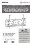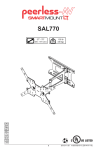
1
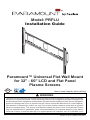
Model: PRFLU
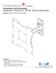
Installation Guide
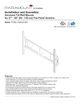
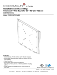
Paramount™ Universal Flat Wall Mount
for 32" - 60" LCD and Flat Panel
Plasma Screens
©
US
Max UL Load Capacity: 200 lb (90.7kg)
:0
6
0000187
2
UL
ID
C
WARNING
This product was designed to be installed on wood stud walls and solid concrete (2000 psi density
minimum) or cinder block walls. Before installing make sure the supporting surface will support the
combined load of the equipment and hardware. Screws must be tightly secured. Do not overtighten
screws or damage can occur or product may fail. Never exceed the Maximum UL Load Capacity.
This product is intended for indoor use only. Use of this product outdoors could lead to product
failure or personal injury. This mount is designed to attach the screen 0.63" from the wall. Please
refer to manufacturer's installation guide recommendations for required distance from wall to
avoid risk of injury or property damage. For support please call customer care at 1-800-865-2112.
ISSUED: 11-02-09 SHEET #: 202-9393-1
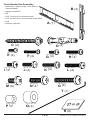
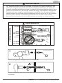
Tools Needed for Assembly
• stud finder ("edge to edge" stud finder is
recommended)
B (2 )
• phillips screwdriver
• drill
• 5/32" (4 mm) bit for wood stud wall
• 5/16" (8 mm) bit for concrete and cinder block
• level
A (1 )
• hammer (optional)
C (4 )
M4 x 12 mm
E (4 )
M6 x 12 mm
I (4 )
M8 x 16 mm
M (6 )
D (4 )
M4 x 25 mm
F (4 )
M6 x 20 mm
J (4 )
M5 x 12 mm
M5 x 25 mm
G (4 )
H (4 )
M6 x 25 mm
M6 x 30 mm
K (4 )
L (4 )
M8 x 40 mm
M8 x 25 mm
O (4 )
N (4 )
T (1 )
ID .22" (5.6 mm)
P (4 )
ID .34" (8.7 mm)
Q (4 )
R (6 )
2 of 27
ISSUED: 11-02-09 SHEET #: 202-9393-1
1
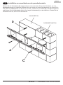
Installation to Double Wood Stud Wall
Use wall plate (A) as a template, make sure it is level, and mark four mounting holes along the center
lines of the wood studs. Drill four 5/32" (4 mm) dia. holes 2.5" (64 mm) deep. Level wall plate (A) and
attach to wall with four wood screws (C) into stud center. Use of an edge to edge stud finder is highly
recommended. Tighten screws firmly, but do not overtighten.
C
A
WARNING
C
WARNING
Wood screws must
center in stud.
Do not over tighten screws, or
damage may occur.
A
3 of 27
STUD
TOP CUTAWAY VIEW
ISSUED: 11-02-09 SHEET #: 202-9393-1
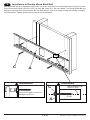
1
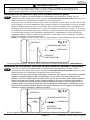
Installing to Solid Concrete or Cinder Block
Level wall plate (A) and use as a template to mark four mounting holes. Drill four 5/16" (8 mm) dia.
holes to a minimum depth of 2.5" (64 mm). Insert four anchors (D) into holes and secure wall plate
(A) with four screws (C). Tighten screws firmly, but do not overtighten.
SOLID CONCRETE
D
CINDER BLOCK
A
C
4 of 27
ISSUED: 11-02-09 SHEET #: 202-9393-1
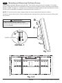
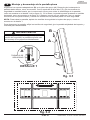
WARNING
• When installing Peerless wall mounts on cinder block, verify that you have a minimum
of 1-3/8" (35 mm) of actual concrete thickness in the hole to be used for the concrete
anchors. Do not drill into mortar joints! Be sure to mount in a solid part of the block, generally 1" (25 mm) minimum from the side of the block. Cinder block must meet ASTM C-90
specifications. It is suggested that a standard electric drill on slow setting is used to drill the
hole instead of a hammer drill to avoid breaking out the back of the hole when entering a
void or cavity.
• Always attach concrete anchors directly to load-bearing concrete.
WARNING
CUTAWAY VIEW
wall plate
CORRECT
CORRECT
plaster/
dry wall
concrete
INCORRECT
wall plate
plaster/
dry wall
concrete
concrete
1
D
Drill holes and insert anchors (D).
2
A
C
D
Place plate (A) over anchors (D). Secure with screws (C). Tighten screws.
5 of 27
ISSUED: 11-02-09 SHEET #: 202-9393-1
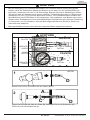
Installing Adapter Brackets
2
To prevent scratching the screen, set a cloth on a flat, level surface that will support the weight of
the screen. Place screen face side down. If screen has knobs on the back, remove them to allow
the adapter brackets to be attached. Place adapter brackets (B) on back of screen, align to
holes, and center on back of screen as shown below. Attach the adapter brackets to the back of
the screen using the appropriate combination of screws, multi-washers, and spacers as shown
in figure 2.1 or 2.2.
NOTE: Top and bottom holes on screen must always be used.
Verify that all holes are properly aligned, and then tighten screws using a phillips
screwdriver.
X
B
CENTER BRACKETS
VERTICALLY ON BACK
OF SCREEN
NOTE: "X" dimensions should be equal.
MULTI-WASHER
MEDIUM HOLE
FOR M5 SCREWS
SMALL HOLE
FOR M4 SCREWS
LARGE HOLE
FOR M6 SCREWS
6 of 27
X
Notes:
• The number of fasteners used
will vary, depending upon the
type of screen.
• Multi-washers and spacers may
not be used, depending upon
the type of screen.
• Use the corresponding hole in
the multi-washer that matches
your screw size.
ISSUED: 11-02-09 SHEET #: 202-9393-1
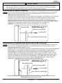
WARNING
• If screws don't get three complete turns in the screen inserts or if screws bottom out and
bracket is still not tightly secured, damage may occur to screen or product may fail.
For Flat Back Screen
2-1
Refer to screen compatibility chart to determine the proper fastener to use. Visit
www.peerlessmounts.com/2 for a full screen compatibility chart for this mount.
Begin with the shortest length screw, hand thread through multi-washer and adapter
bracket (B) into screen as shown below. Screw must make at least three full turns into the
mounting hole and fit snug into place. Do not over tighten. If screw cannot make three full
turns into the screen, select a longer length screw from the baffled fastener pack. Repeat for
remaining mounting holes, level brackets and tighten screws.
NOTE: Spacers may not be used, depending upon the type of screen.
fig 2.1
SCREEN
MULTI-WASHER
SCREW
ADAPTER BRACKET (B)
If you have any questions, please call Peerless customer care at 1-800-865-2112.
For Bump-out or Recessed Back Screen
2-2
Refer to screen compatibility chart to determine the proper fastener to use. Visit
www.peerlessmounts.com/2 for a full screen compatibility chart for this mount.
Begin with longer length screw, hand thread through multi-washer, adapter bracket (B) and
spacer in that order into screen as shown below. Screw must make at least three full turns
into the mounting hole and fit snug into place. Do not over tighten. If screw cannot make
three full turns into the screen, select a longer length screw from the baffled fastener pack.
Repeat for remaining mounting holes, level brackets and tighten screws.
fig 2.2
SCREEN
SPACER
MULTI-WASHER
SCREW
ADAPTER BRACKET (B)
If you have any questions, please call Peerless customer care at 1-800-865-2112.
7 of 27
ISSUED: 11-02-09 SHEET #: 202-9393-1
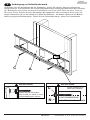
3
Mounting and Removing Flat Panel Screen
Hook adapter brackets (B) onto wall plate (A). Then slowly swing screen in as shown. Turn safety
screws, using allen wrench (T) clockwise at least six times to prevent screen from being removed as
shown in detail 1 of figure 3.1. Always use an assistant to safely lift and position the flat panel screen.
Screen can be adjusted horizontally if desired as shown in figure 3.2.
NOTE: To lock the screen down, tighten safety screws to wall plate as shown in detail 1.
To remove screen from mount, loosen safety screws, swing screen away from mount and lift screen
off of mount.
B
WARNING
Failure to lock brackets (B) with safety
screws can cause sceen to come off mount
if hit accidentally.
A
A
SAFETY SCREWS
B
DETAIL 1
fig. 3.1
fig. 3.2
8 of 27
ISSUED: 11-02-09 SHEET #: 202-9393-1
Modelo: PRFLU
Guía para la instalación
Soporte universal de pared plano
Paramount™ para pantallas LCD y pantallas
planas de plasma de 32" a 60"
©
US
:0
6
0000187
2
UL
ID
C
Máxima capacidad (UL) de carga: 200 lb (90.7kg)
ADVERTENCIA
Este producto está diseñado para ser instalado en paredes con montantes de madera y en
paredes de concreto macizo (de una densidad mínima de 2,000 psi) o de bloques de hormigón.
Antes de instalarlo, asegúrese de que la superficie de apoyo sostendrá la carga combinada
del equipo y los fijadores. No apriete los tornillos en exceso; los podría dañar. Nunca exceda
la Capacidad Máxima (UL) de Carga. Este producto está diseñado para uso en interiores
solamente. Utilizar este producto en exteriores podría causar fallas del producto o lesiones
a individuos. Este soporte está diseñado para sostener la pantalla a 0.63" de la pared. Por
favor, repase las recomendaciones del manual de instalación del fabricante con respecto a
la distancia necesaria de la pared para evitar el riesgo de sufrir lesiones o causar daños a la
propiedad. Si necesita ayuda, por favor, llame a Servicio al Cliente de Peerless al 1-800-865-2112.
PUBLICADO: 11-02-09 HOJA #: 202-9393-1
Español
Herramientas necesarias para el ensamblaje
• localizador de montantes (se
recomienda uno de "borde a borde")
• destornillador phillips
• taladro
• broca de 5/32" (4 mm) para paredes
con montantes de madera
• broca de 5/16" (8 mm) para concreto
macizo o de bloques de hormigón de
escorias
• nivel
• martillo (opcional)
B (2 )
A (1 )
C (4 )
M4 x 12 mm
E (4 )
M6 x 12 mm
I (4 )
M8 x 16 mm
M (6 )
D (4 )
M4 x 25 mm
F (4 )
M6 x 20 mm
J (4 )
M5 x 12 mm
M5 x 25 mm
G (4 )
H (4 )
M6 x 25 mm
M6 x 30 mm
K (4 )
L (4 )
M8 x 40 mm
M8 x 25 mm
O (4 )
N (4 )
T (1 )
ID .219" (5.56 mm)
P (4 )
ID .344" (8.74 mm)
Q (4 )
R (6 )
10 de 27
PUBLICADO: 11-02-09 HOJA #: 202-9393-1
1
Instalación en una pared con montantes de madera dobles
Español
Utilice la placa de pared (A) como plantilla, asegúrese de que esté nivelada y marque cautro
agujeros de montaje a lo largo de las líneas que pasan por el centro de los montantes de madera.
Taladre cautro agujeros de 5/32" (4 mm) de diámetro y 2.5" (64 mm) de profundidad. Nivele la placa
de pared (A) y fíjela a la pared con cautro tornillos de madera (C) en el centro del montante. Se
recomienda utilizar un localizador de montantes de "borde a borde". Apriete los tornillos con firmeza.
No apriete los tornillos en exceso.
C
A
ADVERTENCIA
C
ADVERTENCIA
Pernos largos en el
centro del montante.
No apriete los tornillos en
exceso; los podría dañar.
A
11 de 27
MONTANTE
VISTA SUPERIOR EN CORTE
PUBLICADO: 11-02-09 HOJA #: 202-9393-1
1
Instalación en una pared de concreto macizo o de bloques de
hormigón de escorias
Español
Nivele la placa de pared (A) y úsela como plantilla para marcar cautro agujeros de montaje. Taladre
cuatro agujeros de 5/16" (8 mm) de diámetro a una profundidad mínima de 2 1/2" (64 mm). Inserte
cuatro anclajes (D) en los agujeros y fije la placa de pared (A) a la pared con cuatro pernos largos
(C). Apriete los tornillos con firmeza. No apriete los tornillos en exceso.
CONCRETO MACIZO
D
BLOQUE DE HORMIGÓN
DE ESCORIAS
A
C
12 de 27
PUBLICADO: 11-02-09 HOJA #: 202-9393-1
Español
ADVERTENCIA
• Cuando vaya a instalar soportes de pared de Peerless en bloques de hormigón de escorias, asegúrese de que cuente con una capa de concreto de un grosor mínimo de 1-3/8"
(35 mm) en el agujero, que pueda usar para los anclajes para concreto. ¡No taladre en
juntas de argamasa! Asegúrese de hacer la instalación en la parte sólida del bloque, por lo
general, a un mínimo de 1" (25 mm) del extremo del bloque. Los bloques de hormigón de
escorias tienen que cumplir las especificaciones de la ASTM C-90. Se sugiere utilizar un
taladro eléctrico convencional a baja velocidad para hacer el agujero en vez de un taladro
percutor para no perforar el fondo del agujero al entrar en un vacío o una cavidad.
• Siempre fije los anclajes para concreto directamente en la pared que sostiene la carga.
ADVERTENCIA
VISTA EN CORTE
placa
de pared
CORRECTO
CORRECT
yeso /
tabique de
yeso-cartón
concreto
placa
de pared
INCORRECTO
yeso /
tabique de
yeso-cartón
concreto
1
concreto macizo
D
Perfore los agujeros y después inserte los anclajes (D).
2
A
C
D
Coloque la placa (A) sobre los anclajes (D), fíjela con los tornillos (C). Apriete
los tornillos.
13 de 27
PUBLICADO: 11-02-09 HOJA #: 202-9393-1
Español
Instalación de los soportes adaptadores
2
Para evitar rayar la pantalla, coloque un trapo sobre una superficie plana y nivelada que
soporte el peso de la pantalla. Coloque la pantalla boca abajo. Si la pantalla tiene perillas
en la parte trasera, quítelas para poder fijar los soportes adaptadores. Coloque los soportes
adaptadores (B) en la parte trasera de la pantalla, alinéelos con los agujeros y centralícelos
en la parte trasera de la pantalla, como se muestra abajo. Fije los soportes adaptadores en
la parte trasera de la pantalla utilizando la combinación adecuada de tornillos, arandelas y
espaciadores, como se muestra en la figura 2.1 o en la figura 2.2.
NOTA: Siempre deben usarse los agujeros superiores e inferiores.
Verifique que todos los agujeros estén bien alineados, y después apriete los tornillos utilizando un destornillador phillips.
X
B
CENTRE LOS SOPORTES
VERTICALMENTE EN
LA PARTE TRASERA
DE LA PANTALLAN
X
NOTA: Las dimensiones "X" deben ser iguales.
ARANDELA MÚLTIPLE
AGUJERO
MEDIANO PARA
TORNILLOS M5
Notas:
AGUJERO PEQUEÑO
PARATORNILLOS M4
• Es posible que no tenga que usar las
arandelas múltiples y los espaciadores,
dependiendo del tipo de pantalla.
AGUJERO GRANDE
PARA TORNILLOS M6
• Use el agujero correspondiente en la
arandela múltiple que coincida con el tamaño
de su tornillo.
• La cantidad de fijaciones utilizada variará
según el tipo de pantalla.
14 de 27
PUBLICADO: 11-02-09 HOJA #: 202-9393-1
Español
ADVERTENCIA
• Si los tornillos no pueden atornillarse con tres vueltas completas en los insertos de la
pantalla, o si los tornillos topan fondo y la placa todavía no está firmemente sujeta, se
podría dañar la pantalla o causar la falla del producto.
Instalación de un televisor que tiene la parte posterior plana
2-1
Consulte la Tabla de compatibilidad de las pantallas para determinar cuáles son los
sujetadores adecuados para usarse. Acceda a www.peerlessmounts.com/2 para ver una
tabla completa de las pantallas compatibles con este soporte.
Comience con uno de los tornillos más cortos, enrósquelo, con la mano, a través de la arandela múltiple y el soporte adaptador (B) a la parte posterior de la pantalla, como se muestra
abajo. El tornillo tiene que dar, por lo menos, tres vueltas completas dentro del agujero de
montaje y debe quedar ajustado en su lugar. No apriete los tornillos en exceso. Si el tornillo
no puede dar tres vueltas completas al entrar en la parte posterior de la pantalla, seleccione
un tornillo más largo de los sujetadores identificados y clasificados en las divisiones del
empaque plástico. Siga el mismo procedimiento con los agujeros de instalación restantes,
nivele los soportes y apriete los tornillos.
NOTA: Es posible que no necesite usar los espaciadores, dependiendo del tipo de pantalla.
fig 2.1
PANTALLA
ARANDELA MÚLTIPLE
TORNILLOS
SOPORTE
ADAPTADOR (B)
Si tiene alguna pregunta, por favor, llame a Servicio al Cliente de Peerless al 1-800-865-2112.
Instalación de un televisor que tiene la parte posterior abultada o empotrada
2-2
Consulte la Tabla de compatibilidad de las pantallas para determinar cuáles son los
sujetadores adecuados para usarse. Acceda a www.peerlessmounts.com/2 para ver una
tabla completa de las pantallas compatibles con este soporte.
Comience con uno de los tornillos más largos, enrósquelo, con la mano, a través de la arandela
múltiple, el soporte adaptador (B) y el espaciador, en ese orden, a la parte posterior de la
pantalla, como se muestra abajo. El tornillo tiene que dar, por lo menos, tres vueltas completas
dentro del agujero de montaje y debe quedar ajustado en su lugar. No apriete los tornillos en
exceso. Si el tornillo no puede dar tres vueltas completas al entrar en la parte posterior de la
pantalla, seleccione un tornillo más largo de los sujetadores identificados y clasificados en las
divisiones del empaque plástico. Siga el mismo procedimiento con los agujeros de instalación
restantes, nivele los soportes y apriete los tornillos.
fig 2.2
PANTALLA
ESPACIADOR
ARANDELA MÚLTIPLE
TORNILLOS
SOPORTE
ADAPTADOR (B)
Si tiene alguna pregunta, por favor, llame a Servicio al Cliente de Peerless al 1-800-865-2112.
15 de 27
PUBLICADO: 11-02-09 HOJA #: 202-9393-1
3
Español
Montaje y desmontaje de la pantalla plana
Enganche los soportes adaptadores (B) en la placa de apoyo (A). Después gire lentamente la
pantalla hacia dentro, como se muestra. Con la ayuda de la llave allen (T), gire los tornillos de
seguridad en sentido horario, por lo menos seis veces, para evitar el desmontaje de la pantalla,
como se muestra en el detalle 1 de la figura 3.1. Si lo desea, la pantalla puede ajustarse en sentido
horizontal, como se muestra en la figura 3.2. Siempre cuente con un asistente o con un equipo
mecánico de izar para levantar y colocar los televisores de pantalla plana con más seguridad.
NOTA: Para trabar la pantalla, apriete los tornillos de seguridad a la placa de apoyo, como se
muestra en el detalle 1.
Para desmontar la pantalla, afloje los tornillos de seguridad, gire la pantalla alejándola del soporte y
levántela para desmontarla.
B
ADVERTENCIA
Si no asegura el soporte de gancho (B) con el
tornillo de seguridad, la pantalla sepuede salir
del montaje si se golpea accidentalmente.
A
A
TORNILLO DE
SEGURIDAD
B
DETALLE 1
fig. 3.1
fig. 3.2
16 de 27
PUBLICADO: 11-02-09 HOJA #: 202-9393-1
Modelle: PRALU
Montageanleitung
Paramount™-UniversalFlachbildschirmwandhalter für PlasmaFlachbildschirme von 32 - 60 Zoll
©
US
:0
6
0000187
2
UL
ID
C
Max. Tragfähigkeit (UL): 200 lb (90.7 kg)
ACHTUNG
Dieses Produkt wurde für die Anbringung an Holzständerwänden und Massivbetonwänden (mit einer
Druckfestigkeit von mindestens 2000 psi) oder porenbetonstein ausgelegt. Vergewissern Sie sich vor
der Anbringung, dass die tragende Fläche das Gesamtgewicht der Geräte und der Befestigungsteile
tragen kann. Ziehen Sie die Schrauben fest genug an, dass die Wandplatte sicher befestigt ist, doch
ohne sie zu überdrehen. Durch Überdrehen können die Schrauben beschädigt werden, wodurch
ihr Haltevermögen stark reduziert wird. Die maximale Tragfähigkeit (UL) darf niemals überschritten
werden. Dieses Produkt ist nur für den Gebrauch innerhalb von Gebäuden bestimmt. Eine Verwendung
dieses Produkts im Freien kann zu Produktausfall oder Personenschaden führen. Dieser Halter ist für
die Befestigung des Bildschirms in einem Abstand von 16 mm (0,63 Zoll) von der Wand vorgesehen.
Bitte entnehmen Sie zur Vermeidung von Verletzungen oder Sachschäden den erforderlichen
Wandabstand der Montageanleitung des Herstellers. Falls Sie Unterstützung benötigen, wenden
Sie sich bitte an den Kundendienst unter der Telefonnummer +1-800-865-2112 (innerhalb der USA).
AUSGEGEBEN: 11-02-09 BLATT NR.: 202-9393-1
Deutsch
Für den Zusammenbau erforderliche Werkzeuge
• Balkenfinder (Balkenfinder mit genauer
Kantenanzeige empfohlen)
• Kreuzschlitzschraubendreher
• Bohrer
• 5/32 Zoll (4 mm) Bit für Holzständerwände
• 5/16 Zoll (8 mm) Bit für Betonwände und
Porenbetonstein
• Wasserwaage
• Hammer (optional)
B (2 )
A (1 )
C (4 )
M4 x 12 mm
E (4 )
M6 x 12 mm
I (4 )
M8 x 16 mm
M (6 )
D (4 )
M4 x 25 mm
F (4 )
M6 x 20 mm
J (4 )
M5 x 12 mm
M5 x 25 mm
G (4 )
H (4 )
M6 x 25 mm
M6 x 30 mm
K (4 )
L (4 )
M8 x 40 mm
M8 x 25 mm
O (4 )
N (4 )
T (1 )
ID .219" (5.56 mm)
P (4 )
ID .344" (8.74 mm)
Q (4 )
R (6 )
18 von 27
AUSGEGEBEN: 11-02-09 BLATT NR.: 202-9393-1
1
Deutsch
Anbringung an Holzständerwand
Verwenden Sie die Wandplatte (A) als Schablone, achten Sie darauf, dass sie waagerecht
ausgerichtet ist, und markieren Sie vier Montagebohrungen entlang der Mittellinien der Holzständer. Bohren Sie vier Löcher mit einem Durchmesser von 4 mm (5/32 Zoll) und einer Tiefe von
64 mm (2.5 Zoll). Richten Sie die Wandplatte (A) waagerecht aus und bringen Sie sie mit vier
langen Schrauben (C) an der Wand an in Mitte des Ständers. Am besten eignet sich ein Balkenfinder mit genauer Kantenanzeige. Ziehen Sie die Schrauben fest an, ohne sie zu überdrehen.
C
A
ACHTUNG
C
Ziehen Sie die Schrauben
nicht zu fest an, damit es nicht
zu Beschädigungen kommt.
N
19 von 27
ACHTUNG
Lange Schrauben in
Mitte des Ständers.
HOLZSTÄNDERREIHE
SCHNITTANSICHT VON OBEN
AUSGEGEBEN: 11-02-09 BLATT NR.: 202-9393-1
1
Installation zu massivbeton oder porenbetonstein
Deutsch
Richten Sie die Wandplatte (A) waagerecht aus und verwenden Sie sie als Schablone, um vier
Montagebohrungen zu markieren. Bohren Sie vier Löcher mit einem Durchmesser von 8 mm (5/16
Zoll) und einer Mindesttiefe von 64 mm (2 1/2 Zoll ). Setzen Sie vier Dübel (D) in die Bohrungen ein
und bringen Sie die Wandplatte (A) mit vier langen Schrauben (C) an der Wand an. Ziehen Sie die
Schrauben fest an, ohne sie zu überdrehen.
MASSIVBETON
D
PORENBETONSTEIN
A
C
20 von 27
AUSGEGEBEN: 11-02-09 BLATT NR.: 202-9393-1
Deutsch
ACHTUNG
• Bei der Anbringung von Peerless-Wandhaltern an Porenbetonstein muss sichergestellt
werden, dass die tatsächliche Stärke des Betons, in den das Loch für die Betondübel gebohrt wird, mindestens 35 mm (1 3/8 Zoll) beträgt. Bohren Sie nicht in Mörtelfugen! Achten
Sie darauf, dass die Anbringung an einem massiven Teil des Blocks erfolgt, im Allgemeinen
mindestens 25 mm (1 Zoll) von der Blockseite entfernt. Die Porenbetonsteine müssen den
Spezifikationen der ASTM-Norm C-90 entsprechen. Wir empfehlen, zum Bohren des Lochs
anstelle eines Schlagbohrers einen standardmäßigen Elektrobohrer bei niedriger Einstellung
zu verwenden, um zu verhindern, dass die Bohrungsrückseite beim Eintritt in einen Leeroder Hohlraum ausbricht.
• Betonspreizdübel müssen stets direkt am tragenden Beton angebracht werden.
ACHTUNG
SCNITTANSICHT
WANDPLATTE
RICHTIG
CORRECT
VERPUTZ/
RIGIPS
concrete
BETON
WANDPLATTE
FALSCH
VERPUTZ/
RIGIPS
BETON
BETON
1
D
Bohren Sie Löcher und setzen Sie die Dübel (D) ein.
2
A
C
D
Legen Sie die Platte (A) über die Dübel (D), befestigen Sie sie mit Schrauben (C).
Ziehen Sie die Schrauben fest an.
21 von 27
AUSGEGEBEN: 11-02-09 BLATT NR.: 202-9393-1
Deutsch
Anbringung von Adapterhalterungen
2
Legen Sie ein Tuch auf eine flache, ebene Oberfläche, die das Gewicht des Bildschirms
tragen kann, damit der Bildschirm nicht zerkratzt wird. Legen Sie den Bildschirm mit der
Vorderseite nach unten ab. Falls der Bildschirm über Knöpfe auf der Rückseite verfügt, so
müssen diese entfernt werden, damit die Adapterhaltungen befestigt werden können.
Setzen Sie die Adapterhalterungen (B) auf die Bildschirmrückseite, richten Sie sie an den
Bohrungen aus und zentrieren Sie sie wie unten dargestellt auf der Bildschirmrückseite. Befestigen Sie die Adapterhalterungen unter Verwendung der entsprechenden in Abbildung 2.1
oder 2.2 dargestellten Kombination aus Schrauben, Mehrlochschrauben und Abstandhalter
an der Bildschirmrückseite.
HINWEIS: Es müssen stets die oberen und unteren Bohrungen am Bildschirm verwendet
werden.
Achten Sie darauf, dass alle Bohrungen korrekt ausgerichtet sind und ziehen Sie dann die
Schrauben mit einem Kreuzschlitzschraubendreher an.
X
B
HALTERUNGEN AUF
BILDSCHIRMRÜCKSEITE
SENKRECHT ZENTRIEREN
X
HINWEIS: Die „X“-Abstände müssen identisch sein.
MEHRLOCHSCHEIBE
MITTLERES
LOCH FÜR
M5-SCHRAUBEN
KLEINES
LOCH FÜR
M4-SCHRAUBEN
GROSSES
LOCH FÜR
M6-SCHRAUBEN
HINWEISE:
• Die Anzahl der Schrauben verwendet werden
variieren, je nachdem, welche Art von
Bildschirm.
• Multi-Scheiben und Distanzstücke dürfen
nicht verwendet werden, je nach der Art der
Bildschirm.
• Verwenden Sie das entsprechende Loch
in der Multi-Waschmaschine, die mit Ihrem
Schraubengröße wie gezeigt.
22 von 27
AUSGEGEBEN: 11-02-09 BLATT NR.: 202-9393-1
Deutsch
ACHTUNG
• Sind die Schrauben nicht um drei volle Umdrehungen in die Löcher des Bildschirms eingeschraubt oder stoßen sie unten an und die Halterung ist noch immer nicht sicher befestigt,
kann der Bildschirm beschädigt werden oder das Produkt kann versagen.
Bildschirme mit flacher Rückseite
2-1
Die korrekten Befestigungsteile können der Bildschirm-Kompatibilitätstabelle entnommen
werden. Eine vollständige Bildschirm-Kompatibilitätstabelle für diesen Halter ist unter
www.peerlessmounts.com/2 zu finden.
Hand durch die Mehrlochscheibe und die Adapterhalterung (B) in den Bildschirm. Die Schraube
muss sich um mindestens drei volle Umdrehungen in die Montagebohrung drehen lassen
und gut festsitzen. Nicht zu stark anziehen. Wählen Sie eine längere Schraube aus dem
Befestigungsteilesortiment, wenn sich die Schraube nicht um drei volle Umdrehungen in den
Bildschirm schrauben lässt. Wiederholen Sie diesen Schritt bei den übrigen Montagebohrungen,
richten Sie die Halterungen waagerecht aus und ziehen Sie die Schrauben an.
HINWEIS: Je nach Bildschirmtyp sind keine Abstandhalter zu verwenden.
BILDSCHIRM
Abbildung 2.1
MEHRLOCHSCHEIBE
SCHRAUBE
ADAPTERHALTERUNG (B)
Bildschirme mit Wölbung oder Vertiefung an der Rückseite
2-2
Die korrekten Befestigungsteile können der Bildschirm-Kompatibilitätstabelle entnommen
werden. Eine vollständige Bildschirm-Kompatibilitätstabelle für diesen Halter ist unter
www.peerlessmounts.com/2 zu finden.
Beginnen Sie mit der längeren Schraube und schrauben Sie diese in der unten abgebildeten
Reihenfolge von Hand durch die Mehrlochscheibe, die Adapterhalterung (B) und den
Abstandhalter in den Bildschirm. Die Schraube muss sich um mindestens drei volle
Umdrehungen in die Montagebohrung drehen lassen und gut festsitzen. Nicht zu stark
anziehen. Wählen Sie eine längere Schraube aus dem Befestigungsteilesortiment, wenn
sich die Schraube nicht um drei volle Umdrehungen in den Bildschirm schrauben lässt.
Wiederholen Sie diesen Schritt bei den übrigen Montagebohrungen, richten Sie die
Halterungen waagerecht aus und ziehen Sie die Schrauben an.
BILDSCHIRM
Abbildung 2.2
ABSTANDHALTER
MEHRLOCHSCHEIBE
SCHRAUBE
ADAPTERHALTERUNG (B)
Wenden Sie sich mit Fragen an den Peerless-Kundendienst unter der Telefonnummer
+1-800-865-2112 (innerhalb der USA).
23 von 27
AUSGEGEBEN: 11-02-09 BLATT NR.: 202-9393-1
Deutsch
3
Anbringung und Abnahme des Flachbildschirms
Haken Sie die Adapterhalterungen (B) an der Wandplatte (A) ein. Schwenken Sie den
Bildschirm dann langsam wie dargestellt heran. Drehen Sie die Sicherheitsschrauben
mit Hilfe eines Inbusschlüssels (T) mindestens sechs Mal nach rechts, um ein Entfernen
des Bildschirms zu verhindern (siehe Detailansicht 1 in Abbildung 3.1). Ziehen Sie immer
eine zusätzliche Person heran oder verwenden Sie mechanische Hebegeräte, um den
Flachbildschirm sicher zu heben und zu positionieren.
Der Bildschirm kann auf Wunsch horizontal ausgerichtet werden (siehe Abbildung 3,2).
HINWEISE: Zum Arretieren des Bildschirms ziehen Sie die Sicherheitsschrauben zur
Wandplatte hin an wie in Detailansicht 1 dargestellt.
Zum Entfernen des Bildschirms vom Halter lösen Sie die Sicherheitsschrauben, schwenken
den Bildschirm vom Halter weg und heben ihn vom Halter ab.
B
ACHTUNG
Wenn die Halterung (B) nicht mit den
Sicherheitsschrauben gesichert wird, kann
der Bildschirm bei versehentlichem Anstoßen
vom Halter herabfallen.
A
A
SICHERHEITSSCHRAUBEN
B
Detailansicht 1
Abbildung. 3.1
Abbildung. 3.2
24 von 27
AUSGEGEBEN: 11-02-09 BLATT NR.: 202-9393-1
25 of 27
ISSUED: 11-02-09 SHEET #: 202-9393-1
www.peerlessmounts.com
© 2008 Peerless Industries, Inc.
This warranty gives specific legal rights, and you may also have other rights provided by the national legislation of the country in which you purchased such
product.
This Limited Five-Year Warranty is in lieu of all other warranties, expressed or implied, and is the sole remedy with respect to product defects. No retailer, dealer,
distributor, installer or other person is authorized to modify or extend this warranty or impose any obligation on Peerless in connection with the sale of any product
manufactured or supplied by Peerless.
In no event shall Peerless be liable for incidental or consequential damages or damages arising from the theft of any product, whether or not secured by a security
device which may be included with the product.
This warranty does not cover damage caused by (a) service or repairs by the customer or a person who is not authorized for such service or repairs by Peerless
Industries, Inc., (b) the failure to utilize proper packing when returning the product, (c) incorrect installation or the failure to follow Peerless’ instructions or warnings
when installing, using or storing the product, or (d) misuse or accident, in transit or otherwise, including in cases of third party actions and force majeure.
Any other warranties prescribed by the law which may apply with respect to such products also are limited in duration to the warranty period specified in this
Limited Five-Year Warranty.
Peerless Industries, Inc. establishes a warranty period of five years for products manufactured or supplied by Peerless. This period commences from the date of
sale of the product to the original consumer, but will in no case last for more than six years after the date of the product’s manufacture. During the warranty period
such products will be free from defects in material and workmanship, provided they are installed and used in compliance with the instructions established by
Peerless Industries, Inc. Subject to applicable legal requirements, during the warranty period Peerless will repair or replace, or refund the purchase price of, any
such product which fails to conform with this warranty.
LIMITED FIVE-YEAR WARRANTY
26 of 27
ISSUED: 11-02-09 SHEET #: 202-9393-1
www.peerlessmounts.com
© 2008 Peerless Industries, Inc.
La presente garantía otorga derechos legales específicos, y usted también podría tener otros derechos en virtud de la legislación nacional del país donde usted
compró el producto.
La presente Garantía Limitada de Cinco Años reemplaza cualquier otra garantía expresa o implícita, y es la única reparación con respecto a defectos en el
producto. Ningún comerciante minorista, agente, distribuidor, instalador u otra persona, está autorizado para modificar o prolongar la presente garantía ni para
imponer una obligación a Peerless en relación con la venta de un producto fabricado o suministrado por Peerless.
Peerless en ningún caso será responsable de daños incidentales o indirectos o daños que surjan del robo de un producto, esté o no protegido por un dispositivo
de seguridad incluido con el producto.
La presente garantía no abarca los daños causados por (a) trabajos de servicio, mantenimiento o reparación hechos por el cliente o una persona que no está
autorizada por Peerless Industries, Inc. para realizar esos trabajos, (b) no utilizar un embalaje apropiado al devolver el producto, (c) una instalación incorrecta o
no seguir las instrucciones o advertencias de Peerless al instalar, usar o almacenar el producto, o (d) uso indebido o accidente, en tránsito o de otro modo, incluso
si se trata de acciones atribuibles a terceros o de casos de fuerza mayor.
Cualquier otra garantía exigida por ley que podría ser aplicable con respecto a dichos productos también tendrá una vigencia limitada al período de garantía
especificado en la presente Garantía Limitada de Cinco Años.
Peerless Industries, Inc. establece un período de garantía de cinco años para los productos fabricados o suministrados por Peerless. Este período empieza en
la fecha de venta del producto al consumidor original, pero en ningún caso durará más de seis años después de la fecha de fabricación del producto. Durante
la vigencia de la garantía, dichos productos se encontrarán libres de defectos en sus materiales y fabricación, siempre que se instalen y usen de conformidad
con las instrucciones establecidas por Peerless Industries, Inc. Sujeto a los requisitos legales pertinentes, durante la vigencia de la garantía Peerless reparará o
reemplazará un producto que no cumpla con la presente garantía o reembolsará el precio de compra del mismo.
GARANTÍA LIMITADA DE CINCO AÑOS
Español
27 of 27
ISSUED: 11-02-09 SHEET #: 202-9393-1
www.peerlessmounts.com
© 2008 Peerless Industries, Inc.
Diese Garantie verleiht Ihnen bestimmte gesetzliche Rechte, und Sie verfügen u. U. über weitere Rechte unter der nationalen Gesetzgebung des Landes, in dem
dieses Produkt erworben wurde.
Diese beschränkte fünfjährige Garantie gilt anstelle von allen anderen ausdrücklichen oder stillschweigenden Garantien und ist das alleinige Rechtsmittel bei
Produktdefekten. Kein Einzel-, Vertrags- oder Vertriebshändler und keine mit der Installation beauftragte oder sonstige Person ist befugt, diese Garantie zu ändern
oder zu verlängern oder Peerless irgendwelche Verpflichtungen in Zusammenhang mit einem von Peerless hergestellten oder gelieferten Produkt aufzuerlegen.
Auf keinen Fall haftet Peerless für Neben- oder Folgeschäden oder für Schäden, die aus dem Diebstahl eines Produkts entstehen, unabhängig davon, ob das
Produkt durch eine mitgelieferte Sicherheitsvorrichtung gesichert war oder nicht.
Diese Garantie gilt nicht bei Schäden, die aufgrund folgender Ursachen entstanden: (a) Wartung oder Reparatur durch den Kunden oder einer Person, die nicht
von Peerless Industries Inc. für die Durchführung solcher Wartungs- oder Reparaturarbeiten autorisiert wurde, (b) Nichtverwendung von geeigneter Verpackung
bei der Rücksendung des Produkts, (c) falsche Installation oder Nichtbefolgung bzw. Nichtbeachtung von Peerless-Anweisungen oder -Warnhinweisen bei der
Installation, Verwendung oder Lagerung des Produkts oder (d) Missbrauch oder Unfall, während des Transports oder anderweitig, einschließlich Handlungen
Dritter und höherer Gewalt.
Andere gesetzlich vorgeschriebene Garantien, die auf solche Produkte zutreffen können, sind in ihrer Dauer ebenfalls auf die Frist beschränkt, die in dieser
beschränkten fünfjährigen Garantie festgelegt ist.
Peerless Industries Inc. gewährleistet auf Produkte, die von Peerless hergestellt oder geliefert werden, eine Garantiefrist von fünf Jahren. Die Frist beginnt mit
dem Datum des Produktverkaufs an den ursprünglichen Verbraucher; sie gilt jedoch in keinem Fall länger als sechs Jahre nach Herstellungsdatum des Produkts.
Während der Garantiefrist weisen solche Produkte keine Material- oder Verarbeitungsfehler auf, vorausgesetzt, sie werden gemäß den Anweisungen von Peerless
Industries Inc. installiert und verwendet. Vorbehaltlich der einschlägigen rechtlichen Verpflichtungen repariert oder ersetzt Peerless während der Garantiefrist ein
Produkt, das dieser Garantie nicht entspricht, oder erstattet den Kaufpreis dafür.
BESCHRÄNKTEN FÜNFJÄHRIGEN
GARANTIE
Deutsch