1
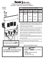
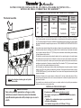
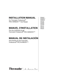
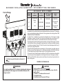
B A C K G U A R D I N S TA L L AT I O N I N S T R U C T I O N S — P R O H A R M O N Y ™ D U A L F U E L R A N G E S
BACKGUARD MODEL NUMBERS
Front of Range
Range
Width
6”
Low Back
9”
Low Back
30”
Included with
Range
N/A
PA30GHSH
36”
N/A
PA36GLBH
PA36GHSH
PA48GLBH
PA48GHSH
48”
The back panel of backguard is positioned
inside these two guide channels on the back of
the range.
N/A
22” Pot and
Pan Shelf
Island
Trim
PA30GITH
Included with
Range
Included with
Range
• The backguard must be attached before sliding the range into the final, installed position. A Low Back or Pot-and-Pan Shelf must be installed when there is less than 12” clearance
from a combustible back wall and the back of the range above the cooking surface. SEE
RANGE INSTALLATION MANUAL. • An Island Trim is available for covering the backguard area of the range for island
installations; however, the Island Trim can only be used where there is a minimum of 12”
horizontal clearance between a combustible back wall and the back of the range. • The backguard is inserted inside the guide channels on the back of the range, as shown
in the illustration. (Remove the griddle or grill assembly for sufficient installation clearance
on models so equipped.) Using a T-20 size Torx driver, fasten the backguard with four (4)
screws to the range side panels. • Pot-and-Pan Shelf models require pre-assembly of the top panel to the shell using nine
(9) of the enclosed Torx head screws. For sufficient load strength, YOU MUST attach two
(2) Torx head screws through the back corners of the top down into the shell. • To secure the front of the back guard, install three (3) of the Torx head screws through the
lower front panel of the backguard, into the flange at the back of the range’s cooktop. • The Pot-and-Pan Shelf models provide a shelf above the cooktop to keep foods hot or
store cooking pans.
WARNING
To avoid possible burn or fire hazard, a backguard designed
specifically for this range must be installed whenever the
range is used.
OBSERVE CAUTIONS BELOW.
CAUTION
The Pot and Pan Shelf can get very hot!
DO NOT place any of the following items on top of the Pot
and Pan Shelf:
• “Plastics” or containers that can melt.
• Flammable items.
• A total load over 30 pounds (13.6 kg).
I N S T R U C T I O N S D ’ I N S TA L L AT I O N D U D O S S E R E T —
CUISINIÈRES À COMBUSTION JUMELÉE PRO HARMONY™
Devant de
cuisinière
NUMÉROS DE MODÈLES DU DOSSERET
Largeur de
cuisinière
Le panneau arrière du dosseret est à l’intérieur
de ces 2 guides au dos de la cuisinière.
Dosseret
bas 6 po
Dosseret
bas 9 po
Tablette à
casserole 22 po
Garniture
d’îlot
30 po
Compris avec
la cuisinière
N/D
PA30GHSH
PA30GITH
36 po
N/D
PA36GLBH
PA36GHSH
Compris avec
la cuisinière
48 po
N/D
PA48GLBH
PA48GHSH
Compris avec
la cuisinière
• Le dosseret doit être installé avant de glisser la cuisinière en position. Le modèle profilé
ou la tablette doit être installé lorsqu’il y a moins de 12 po de dégagement entre le mur
arrière combustible et le dos de la cuisinière, au-dessus de la surface de cuisson. VOIR
LE GUIDE D’INSTALLATION DE LA CUISINIÈRE. • Une garniture d’îlot est disponible pour couvrir le dosseret pour les installations en îlot;
toutefois elle peut seulement être utilisée lorsqu’il y a un minimum de dégagement
horizontal de 12 po entre le mur arrière combustible et le dos de la cuisinière. • Le dosseret est inséré dans les guides au dos de la cuisinière, comme illustré. (Enlever
la grille ou l’assemblage gril pour un dégagement suffisant pour l’installation pour les
modèles ainsi équipés.) Avec une clé dynamométrique T-20, fixer le dosseret avec 4 vis
sur les panneaux latériaux de la cuisinière. • La tablette requiert un assemblage du panneau supérieur au boîtier à l’aide de 9 vis à
tête Torx. Pour une résistance de charge suffisante, IL FAUT fixer 2 vis par les coins
arrière du haut dans le boîtier. • Pour fixer le devant du dosseret, installer 3 vis Torx par le panneau avant inférieur du
disseret, dans le rebord au dos de la surface de cuisson de la cuisinière. • La tablette au-dessus de la cuisson permet de garder les aliments chauds ou ranger
des casseroles.
OBSERVER LES AVERTISSEMENTS CI-DESSOUS.
AVERTISSEMENT
Pour éviter brûlure ou risque d’incendie, le dosseret est
conçu spécifiquement pour cette cuisinière et doit être
installé chaque fois que la cuisinière est utilisée.
ATTENTION
La tablette peut être très chaude !
NE PAS placer ces articles sur le dessus de la tablette à
casseroles :
• « plastique » ou contenant pouvant fondre.
• articles inflammables.
• charge totale de 30 lb (13.6 kg).
I N S T R U C C I O N E S D E I N S TA L A C I Ó N D E L A C O N S O L A T R A S E R A D E P R O T E C C I Ó N —
E S T U FA S D E D O B L E C O M B U S T I B L E P R O H A R M O N Y ™
NUMEROS DE MODELOS DE CONSOLA TRASERA
Ancho de
estufa
Frente de la estufa
La consola trasera de protección se instala
adentro de estos dos canales guía en la parte
trasera de la estufa.
ADVERTENCIA
6” Consola
Baja
9” Consola
Baja
22” Estante para
Ollas y Sartenes
30”
Incluida con
estufa
N/D
PA30GHSH
36”
N/D
PA36GLBH
PA36GHSH
48”
N/D
PA48GLBH
PA48GHSH
Ajuste
de Isla
PA30GITH
Incluida con
estufa
Incluida con
estufa
• Se debe instalar la consola trasera de protección antes de deslizar la estufa a su posición
final. Se debe instalar una consola trasera baja o un estante para ollas cuando hay menos de
12” (30.5cm) de espacio libre entre materiales combustibles (pared trasera) y la parte trasera
de la estufa arriba de la superficie para cocinar. VEA EL MANUAL DE INSTALACIÓN DE LA
ESTUFA. • Una moldura tipo isla está disponible para tapar el área de la consola trasera de la estufa con
instalaciones tipo isla; sin embargo, se puede utilizar la moldura tipo isla solamente cuando
hay un espacio mínimo libre de 12” (30.5cm) entre materiales combustibles (pared trasera)
y la parte trasera de la estufa. • Se instala la consola trasera de protección adentro de los canales guía en la parte trasera
de la estufa como se muestra en la ilustración. (Quite el conjunto de la plancha o del asador
en las estufas con plancha o asador para tener suficiente espacio libre para la instalación en
modelos así equipados.) Usando un destornillador Torx tamaño T-20, fije la consola trasera
con (4) tornillos a los paneles laterales de la estufa. • En los modelos con estante para ollas se debe ensamblar primero el panel superior al armazón
usando nueve (9) de los tornillos de cabeza torx incluidos. Para lograr suficiente fuerza de carga,
USTED DEBE fijar dos (2) tornillos de cabeza Torx a través de las esquinas traseras de la parte
superior al armazón.
• Para fijar el frente de la consola trasera, instale tres (3) de los tornillos de cabeza Torx a
través del panel delantero inferior de la consola trasera en la brida de la parte trasera de la
parrilla de la estufa. • Los modelos con estante para olla tienen un estante arriba de la parrilla para mantener
calientes alimentos o para guardar ollas.
OBSERVE LAS PRECAUCIONES ABAJO.
Para evitar posibles quemaduras o fuego, se debe
instalar una consola trasera de protección diseñada
específicamente para esta estufa, siempre que se use la
estufa.
PRECAUCIÓN
El estante para ollas puede calentarse mucho!
NO coloque cualquiera del siguiente encima de el estante
para ollas:
• “plásticos” o contenedores que se pueden derretir.
• artículos inflamables.
• una máxima carga arriba de 30 libras (13.6 kg).
5551 McFadden Avenue, Huntington Beach, CA 92649 • 800-735-4328 • www.thermador.com
9000476088 • 5U02LA • Rev. A • 06/09 • © BSH Home Appliances Corporation, 2009 • All rights reserved
Litho in USA