1
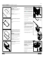
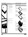
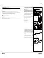
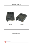
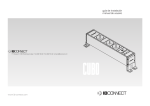
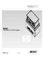
guía de instalación installation guide
manual de usuario user manual
MEETING
concepto máximo de integración
maximum concept of integration
0000000-03
10 - 11
índice table of contents
manual de usuario user manual
Antes de comenzar Before starting
Vista de los componentes View of components.......................................03
puesta en marcha y funcionamiento start-up and operation
Esquema del producto Product schematic diagram
Advertencias Warnings............................................................................ 04
Vista de los componentes View of components.......................................05
01
Una vez la caja esta instalada definitivamente en la mesa, seguir los siguientes pasos.
Guía de instalación Installation guide
Guía de instalación Installation guide............................................................06
IMPORTANTE: Conectar el cable de alimentación de corriente eléctrica y los cables
de multimedia.
Grupos electrónicos posventa Electronics group after-sales
Sustitución Replacement................................................................................10
Once the unit is fully installed on the table, follow these steps
.
IMPORTANT: Connect the electrical power supply cable and the multimedia cables.
Manual de usuario User manual
Puesta en marcha y funcionamiento Start-up and operation...................11
02
características técnicas technical specifications
Eléctrico
Electricity
Tensión nominal: 230V a.c monofásico.
Intensidad nominal: 16 Amp máximo.
Frecuencia: 50Hz.
Sistema de apertura:Eléctrico.
Nominal voltage: 230 V a.c. monophase.
Nominal current: maximum 16 amps.
Frequency: 50 Hz.
Opening system: Electricity.
Tipos de conexiones
Connection types
• Alimentación eléctrica: Toma GST18.
• Salidas de corriente: Tomas Schuko.
• Voz y Datos: RJ45 Cat. 6
• Conexiones multimedia.
• Power supply: GST18 socket.
• Output current: Schuko socket.
• Voice and Data: RJ45 Cat. 6
• Multimedia connections.
Gruesos de mesa: 25 / 30 / 40 mm.
Para grosores superiores a 40 mm.
es necesario realizar rebaje del tablero.
Table thicknesses: 25 / 30 / 40 mm
Table-tops will need to be recessed if they
are thicker than 40 mm.
• Grueso de tapa: 5 mm.
• Dimensiones caja: 356 x 194 x 163 mm.
• Cover thickness: 5 mm.
• Box dimensions: 356 x 194 x 163 mm.
Pulsar el botón de accionamiento manual hasta completar el ciclo entero y comprobar
que funciona bien y que la tapa queda enrasada a la mesa una vez cerrada.
Press the manual operation button until the full cycle has completed, check that it works
properly and that the cover is flush with the table once it is closed.
03
Accionar la caja desde el botón superior, y comprobar que actúa sobre la caja.
Operate the unit using the button and check that the button works with the unit.
06 - 07
guía de instalación installation guide
01
Practicar el corte en el tablero.
362 +1
-0
200 +0
-0,2
IMPORTANTE: El radio de acabado de las
esquinas no podrá ser superior a 2 mm.
Los siguientes pasos hay que realizarlos con
la caja abierta. Para ello, conectela a la red,
pulsar el botón rojo de accionamiento manual,
y una vez abierta desconectarla de la red.
Cut into the table top.
Soltar los cuatro tornillos de las sujeciones
(pestañas) del marco perimetral de plástico.
IMPORTANT: The finished radius of the
corners may not surpass 2 mm.
Sacar el marco perimetral completamente.
Radio 2 mm.
Radius 2 mm.
02
Utilizar el material extraido del corte para realizar
la tapa.
353
+0
-0,2
Use the material removed from the cut to make
the cover.
5 +0,2
-0
191 +0
-0,2
Tornillos.
Screws.
A
Torn
Torn
Detalle A
A Detail
The following steps must be carried out with the
unit open. To do this, connect the power, push
the red manual operation button and disconnect
the power once opened.
Botón rojo.
Red button.
Loosen the four fastening screws (tabs) from the
outside plastic flange.
06
Completely remove the outside flange.
Posicionar la caja por la parte inferior del tablero.
La caja dispone de cuatro pestañas que sirven
de guía para su correcto posicionamiento
(detalle A).
La pestaña de sujeción debe quedar perfectamente
apoyada sobre el tablero antes de atornillar.
Aplicar el adhesivo suministrado e introducirla
en la base de plástico. El no utilizar este
adhesivo puede causar problemas de mala
fijación.
03
05
Position the unit on the lower part of the tabletop. The unit has four tabs, which serve as a
guide for positioning (detail A).
The fastening tab must be perfectly supported
on the table-top before screwing.
Pestañas.
Tabs.
A
Pestañas.
Tabs.
IMPORTANTE: Si es el caso, respete la
posición y dirección de la veta de la madera.
Apply the adhesive supplied to the plastic base.
If this adhesive is not used, there may be
problems with incorrect fastening.
Detalle A
A Detail
IMPORTANTE: If this is the case, respect the
position and grain direction of the wood.
Retirar la protección inferior de la caja soltando
los tornillos de sujeción.
04
Remove the lower protective cover by loosening
the fastening screws.
Tornillos.
Screws.
Atornillar las cuatro esquinas de la pestaña de
sujeción al tablero, sin apretar totalmente, para
poder alinear la caja posteriormente. Una vez
alineada colocar el resto de los tornillos.
IMPORTANTE: Nunca manipular los tornillos
inferiores de nivelación.
Screw the four corners of the fastening tab to
the table-top without fully fastening so that the
unit can be aligned. Once aligned, fasten the
rest of the screws.
IMPORTANT: Never manipulate the lower
levelling screws.
Tornillos.
Screws.
A
07
Detalle A
A Detail
guía de instalación installation guide
08
04 - 05
esquema del producto product schematic
Introducir el marco perimetral por la parte
superior hasta que encaje sobre el tablero.
vista de los componenentes view of components
IMPORTANTE: Supervisar que el marco
perimetral se introduce en la posición correcta.
Tapa
Cover
IMPORTANTE: Vigile que cada pestaña se
introduce en su alojamiento.
Fit the outside flange through the upper part
until it is enclosed on the table-top.
IMPORTANT: Check that the outside flange is
in the correct position.
Corte del material de la mesa
según plano.(No se suministra)
Fijación tapa
Cover fastening
Material cut from the table
according to drawing (not supplied).
Marco perimetral
Outside flange
Botón accionamiento
IMPORTANT: Ensure that each tab is fitted into
its housing.
Button of operation.
Pestañas sujeción marco
perimetral.
09
Tornillos.
Screws.
Retocar el posicionamiento de la caja hasta
alinearla.
Outside flange fastening tabs.
Apretar los tornillos para terminar de sujetar la
caja al tablero.
Tornillos sujeción a mesa.
Adjust the unit's position until it is aligned.
Caja
Unit
Screws for fastening to the table.
Tighten the screws to finish fastening the unit
to the table.
Adhesivo
Adhesive
Protección inferior
Lower protective
covering
Tornillos sujeción marco
perimetral.
Outside flange fastening screws.
Sujeción protección inferior.
Lower protective cover fastening.
08 - 09
advertencias warnings
Una vez sujeta la caja, regular las sujeciones
del marco perimetral.
Advertencias importantes a tener en cuenta.
IMPORTANTE: Asegurarse previamente de
introducir correctamente las puntas de los
tornillos fijos en los agujeros de las patillas del
marco.
IMPORTANTE: Mantener siempre la tapa de la caja despejada de cualquier objeto.
Mantener el perímetro de la caja libre de cualquier objeto para que los movimientos de apertura
y cierre sean completos. Evitar el derrame de líquidos sobre la caja.
Important warnings to be kept in mind:
IMPORTANT: Always ensure that the unit's lid is clear from any object.
Ensure the area around the unit is free from any objects so that it can completely open and close
freely. Avoid spilling liquids on the unit.
10
A
Las patillas disponen de tres agujeros diferentes
para los distintos espesores de mesa.
Tornillos.
Screws
Once the unit has been fastened, adjust the
fastenings on the outside flange.
IMPORTANT: Before fitting the screws, ensure
they correctly match up with the holes in the
edges of the flange.
ok
Detalle A
A Detail
The edges of the flange have three different
holes for the different table thicknesses.
MAL
Colocar la protección inferior y atornillar los
cuatro tornillos. Una vez colocado todo, conecte
la caja a la red eléctrica y las conexiones
multimedia. La caja esta preparada para ser
utilizada.
11
Fit the lower protective cover and screw on with
the four screws. Once completely fitted, connect
the unit to the electrical network and multimedia
connections. The unit is now ready for use.
Tornillos.
Screws.
grupos electrónicos electronic groups
antes de comenzar before starting
sustitución y regulación replacement and regulation
Instalador:
Este producto debe ser instalado por un
especialista cualificado.
La instalación tiene que estar protegida con un
diferencial para proporcionar la protección contra
sobrecarga, cortocircuitos y derivación a tierra.
El no obedecer esta norma, puede ser peligroso.
01
Tarjeta de control.
Control card
.
Cod.4060542
Porta fusible.
01
Tornillos.
Screws.
Piezas de sustitución.
Replacement parts.
Reemplazar fusible y tarjeta de control.
Abrir el portafusible tirando de este y reemplazar
el fusible dañado.Fig.2
This product is only for use in internal facilities.
Diseñado exclusivamente para empotar en
mesas de oficinas.
It is designed exclusively for fitting into office
tables.
No requiere ningún tipo de instalación interior
tanto para las conexiones eléctricas como las
de multimedia.
No internal installation is required either for electrical
or multimedia connections.
Viene totalmente graduado al grueso de la mesa
del cliente, por lo que no es necesario manipular
para su nivelación.
As it comes fully scaled to the thickness of the
customer's table, there is no need to handle it
for levelling.
Si existe cualquier duda en la instalación,
póngase en contacto con el departamento
técnico de IB Connect.
If there are any doubts about installation, contact
the IB Connect technical department.
Usuario:
La manipulación interna de este producto debe
realizarse exclusivamente por personal
especializado.
User:
The internal handling of this product must only
be carried out by specialised personnel.
Todos los productos de IB Connect superan un
riguroso control de calidad.
All IB Connect products surpass rigorous quality
control.
Si por cualquier motivo, su equipo sufriera una
malfuncionamiento, no dude en ponerse en
contacto con:
If the equipment malfunctions for any reason,
do not hesitate to contact:
Disconnect MEETING from the power current.
Remove the aluminum housing (Pic. 01)
Ser vicio de Asistencia Técnica IB
Connect:
IB Connect Technical Support Service:
Unscrew the lid of electronic card access (Pic.2).
Teléfono: +34 948 753 282
Telephone: +34 948 753 282
e-mail: [email protected]
e-mail: [email protected]
Para cualquier consulta, visite:
www.ib-connect.com
For any query, visit:
www.ib-connect.com
Replace fuse and control card. Pull the fuseholder to open it and replace the damaged fuse
(Fig. 2).
Loosen the lower protective cover and unscrew
the card access cover as shown in figure 2.
Disconnect the cables and replace with new
ones; connect the cables and screw on the card
access, replace the lower protective cover.
Una vez que tenemos la tarjeta electrónica a
la vista, localizamos los dos reguladores (A yB)
solo haremos girar el (B) y con un destornillador
muy fino los hacemos girar un poquito en el
sentido contrario a las agujas de reloj.Una vez
realizada la maniobra volvemos a conectar la
caja pulsamos el botón para ver si sube y baja
bien.Si no funciona bien volvemos a darle un
poquito mas a regulador y volvemos a probar.
replacement
5% 5%
5%
5%
5%
5%
5%
5%
regulador A
regulator A
A
B
regulador B
regulator B
Installer:
This product must be installed by a qualified
specialist.
The installation must be protected with a
differential to provide protection against overload,
short-circuits and earth bypass.
It may be dangerous if this rule is not complied
with.
Este producto debe utilizarse exclusivamente
en instalaciones interiores.
Soltar la protección inferior, desatornillar la tapa
de acceso a tarjeta, como se muestra en la
fig.2. Desconectar los cables de la tarjeta y
sustituir por otra nueva, conectar los cables y
atonillar la tapa de acceso a tarjeta, colocar la
protección inferior.
Desconectar la caja de la red eléctrica.
Soltar el embellecedor principal Fig1.
Desatornillar la tapa de acceso a tarjeta, como
se muestra en la fig.2.
02
02 - 03
The electronic card has 2 regulators. (A and B).
With a very fine screwdriver, turn the regulator
B to opposite direction of the clockwise (a
quarter turn screw).Connect MEETING to the
power current and check if it works correctly.
In case that it is not working, please repeat the
process (turn regulator B a bit more, no more
than a quarter turn, to the opposite direction of
the clockwise until it is solved).