1
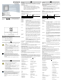
E GB ¡Importante! Lea detenidamente estas instrucciones antes de instalar. Se declina toda responsabilidad y garantía sobre daños derivados por no seguir estas instrucciones de instalación. No se aceptará responsabilidad alguna por cualquier pérdida o daño. Información de seguridad NUNCA conecte el IQ8FCT directamente a 220Vac. Instale en ambientes dentro el rango de temperatura especificado. Solo técnicos cualificados, que estén familiarizados con los riesgos específicos y las normativas correspondientes, deben llevar a cabo las operaciones de reparación y mantenimiento del equipo. El IQ8FCT no debe ser alterado ni modificado. General El módulo IQ8FCT (Ref. 804867) está diseñado para alarmas técnicas de dentro de lugares secos, en áreas sin riesgo de explosión. El funcionamiento se indica con el parpadeo del LED Verde (H); (Fig. 4). Manual de Instalación IQ8FCT Installation Instruction IQ8FCT (Art.-Nr. / Part No. 804867) 798826 02.2011 E Requerimientos del Sistema Cambios técnicos reservados Technical changes reserved! GB © 2011 Honeywell International Inc. Central / IQ8FCT Versión de Software IQ8Control desde Versión V3.08 FlexES control --- IQ8FCT desde Versión V6.09 desde Versión V1.15 Funcionamiento Suba la cubierta de llave (A) e inserte la llave. Instalación Montaje empotrado: Montaje en Superficie: Terminales 1-4 ULIN (Entrada) ULOUT (Salida). Use cable de comunicaciones claramente identificado I-Y (St) Y n x 2 x 0.8 mm o cable para alarma de incendio. La conexión de la malla del cable debe realizarse al Terminal de tierra para evitar interferencias. Use junta de paso para cableado para evitar el acceso de humedad. Antes de conectar cargas inductivas o equipos de alarma, asegúrese de si para cada equipo conectado se precisa el diodo suministrado (Tipo 1N4007). Información adicional y actualizada Las especificaciones se refieren a la fecha de creación del documento y pueden ser modificadas o variadas sobre la normativa aplicada o la información facilitada. Para información actualizada y homologaciones consulte www.esser-systems.de. Revise el Catálogo de Protección contra Incendios para ver otros accesorios. esserbus® y essernet® son marcas registradas en Alemania. El IQ8FCT se instala sobre caja de superficie (opcional) o con marco de montaje universal (opcional). Instale el IQ8FCT de forma segura, en una pared apropiada sobre una superficie lisa, ej. con 2 tornillos (Long. 40 mm) y tacos adecuados (S6) (Fig. 7/8). FlexES control --- IQ8FCT from Version V6.09 Operation Installation Flush mounting The IQ8FCT is installed on a conventional standard housing (Ø 55 – 60 mm). Surface mounting The IQ8FCT is installed on a back box for surface mounting (option) or with a universal installation frame for wall mounting (option). The call point securely on a suitable wall with a smooth surface, e.g. with 2 screws (length 40 mm) and dowels (S6) (Fig. 7/8). Insert the key with the both tenons in the opening at the bottom of the housing (Fig. 2) to release the cover lock. Lift up the bottom edge of the cover a little to release it and then remove it. Closing: Símbolo: Abra la carcasa como se ha indicado y quite la lámina transparente de plástico (D/E) presionando hacia afuera, coloque la etiqueta de identificación adecuada desde la parte frontal, coloque la cubierta y presione hasta su posición (Fig. 3). Turn key lock anti-clockwise until the left stop position (Fig. 6). Position the upper edge of the cover in the groove at the top of the base and then press the cover down until it locks into position. Symbolism: Open the housing and remove the transparent plastic cover (D/E) by prising it out. Insert the appropriate identification label from the front. Align the cover and snap it back into place (Fig. 3). Plastic screen: Turn key lock clockwise until the right stop position (Fig. 5). Insert screen aligned (J) in the front recess und move screen upwards by turning the key anti-clockwise until the left stop position (Fig. 6). Terminals: The terminals (Fig. 10) can be removed to simplify the installation. Lámina de plástico: Gire la llave en sentido horario hasta el tope derecho (Fig. 5). Inserte la lámina o cristal en su posición (J) en el hueco frontal, deslice la lámina hacia arriba girando la llave en sentido antihorario hasta su tope izquierdo (Fig. 6). Terminales: Los terminales pueden extraerse para facilitar la instalación (Fig. 10). Conexionado Típico (Fig. 10) El transponder IQ8FCT se conecta al lazo analógico (terminales 1-4) de los sistemas de control de incendios de centrales IQ8Control / FlexES. Aislador de cortocircuito Los aisladores de cortocircuito de lazo aseguran el funcionamiento de los equipos, incluso en el caso de pérdida parcial debido a cortocircuito en el lazo. Cuando sucede un cortocircuito, los aisladores anterior y posterior al cortocircuito se abren aislando el tramo entre aisladores. Un solo corte o cortocircuito no afecta al funcionamiento del lazo. Entrada de contacto La longitud total del la línea de entrada no puede exceder los 500 metros (ejemplo de cableado Fig.11). Si no se ha conectado contacto externo, debe instalarse una resistencia final de línea de 10 KOhm (± 5 %) entre los terminales 7-8 (Fig. 10). Relé / Funcionamiento Los terminales del relé seco se encuentran entre los terminales 5-6 (Fig. 10). El relé, por defecto, funciona como NA (Normalmente Abierto). La activación de la salida de relé puede configurarse en la programación del panel de control y modo de funcionamiento NC (Normalmente Cerrado) del contacto debe configurarse con el software de programación tools 8000. Consumo máximo por el contacto : 30 V cc / 1 A o 30 Vac / 1 A : 8 Vdc a 42 Vdc Consumo reposo @ 19 V DC : 45 µA aprox. @ 19 Vdc Observe the correct wiring sequence for the loop! Consumo alarma : 9 mA aprox., pulsante Terminals 1-4 ULIN (Input) ULOUT (Output). Número Equipos : máx. 127 IQ8FCT por lazo Use designated communication cable I-Y (St) Y n x 2 x 0.8 mm or fire alarm cable! Indicación alarma : LED rojo Indicador funcionamiento : LED verde Terminales : máx. 2.5 mm² (AWG 26-14) Temperatura trabajo : -20 °C a +70 °C Temperatura almacenamiento : -30 °C a +75 °C Grado de protección : IP 43 (en caja) : IP 55 (con opción) Connection of the cable shield to the ground terminal protects the signal cables against interference. Install inlying cable with a dripping bend to protect the device from dampness. Before connecting inductive loads and alarm devices ensure for each connected device if the supplied diode (type 1N4007) is required for a proper wiring! Additional and updated Informations Caja : PC/ASA plástico The product specification relate to the date of issue and may differ due to modifications and/or amended Standards and Regulations from the given information. For updated information and declaration of conformity refer to www.esser-systems.de. Color : Gris (similar RAL 7035) Peso : 110 g aprox. Dimensiones (a x h x f) : 88 x 88 x 21 (mm) Diemnansiones con caja sup. : 88 x 88 x 57 (mm) Refer to the Fire Alarm System Catalogue for additional accessories. in from Version V1.15 Opening: Características Técnicas are registered trademarks from Version V3.08 Gire la llave en sentido antihorario hasta su tope izquierdo (Fig. 6). Coloque la lengüeta superior de la cubierta sobre las ranuras del módulo del pulsador y presione hasta encajar la cubierta en su posición. Alimentación GB Programming software tools 8000 System software IQ8Control Push up the keyhole cover (A) to insert the key. El IQ8FCT puede instalarse sobre caja de mecanismo estándar (Ø 55 – 60mm) Cubierta Abatible: Para aumentar el grado de protección de IP43 a IP55. Ref. 704965 La cubierta abatible (M) se inserta en los orificios laterales (N) (opcional) de la carcasa y puede precintarse en caso necesario (B) (Fig. 2/9). Observe la secuencia correcta en el cableado de lazo analógico! and essernet System requirements Panel / IQ8FCT La pantalla del cable debe interconectarse en regleta aparte. La caja de superficie tiene un terminal apropiado para conectar la pantalla (opcional) (Fig. 7). E esserbus Germany. The IQ8FCT may not be changed or modified in any way. General The IQ8FCT (Part No. 804867) is designated for hazard alarms in dry workplaces not subject to explosion hazards. The operation mode is displayed via the flashing green LED (H); (Fig. 4). Cierre: E-Mail: [email protected] ® Only qualified technicians who are fully familiar with all the associated hazards and the applicable legislation and regulations may perform maintenance and repair work on the call point. Inserte la llave por sus dos patillas en los orificios inferiores de la cubierta (abajo). Presione hacia arriba para liberar la tapa (Fig. 2). Tire desde abajo hacia fuera hasta retirar la tapa. Internet: www.esser-systems.de ® Only operate in the specified ambient temperature range. Apertura: Novar GmbH a Honeywell Company Dieselstraße 2, D-41469 Neuss Programa Configuración tools 8000 Important! Read these instructions carefully before starting assembly. Claims under warranty will be invalidated in the event of damage caused by noncompliance with the installation instructions. No liability is accepted for any resulting consequential loss or damage. Safety information NEVER connect the IQ8FCT directly to a 230 V AC mains power supply. Especificación : EN 54-17 : 2005 / -18 : 2005 Certificado VdS : G 20138 Certificado CE : 0786-CPD-20792 The cable shield of the connection cable must be interconnected by using a single terminal block. The back box (option) provides an integrated terminal for the shield connection (Fig. 7). To increase the protection rating from IP 43 up to IP 55. Hinged cover: Part No. 704965 (Option) The hinged cover (M) is fixed by the sideway dents (N) of the housing and may be sealed (B) if required (Fig. 2/9). Typical wiring (Fig. 10) The IQ8FCT are connected (terminals 1-4) to the loop of the System IQ8Control / FlexES control fire alarm control panel. Zone isolator The zone isolators ensure that the system continues to function even if a segment of the loop circuit fails due to a short circuit. When a short circuit occurs the zone isolators before and after the short circuit open, disconnecting the section of the loop between the isolators. Simple wire breaks do not affect the functionality of the loop circuit. Contact The total cable length of the external contact should not exceed 500 meters! (wiring example Fig. 11). If no external contact is connected the 10 KOhm (± 5 %) terminating resistor must be installed directly to terminals 7/8 (Fig. 10). Contact response /Operating mode The dry contacts of a relay are available on terminals 5 / 6 (Fig. 10). The relay is operated as NO contact by factory settings. The relay output can be programmed as a control zone in the customer data of the fire alarm control panel and the NC (normally closed) operating mode must be programmed with the programming software tools 8000. Maximum contact rating : 30 V DC / 1 A or 30 V AC / 1 A Specifications Power supply : 8 V DC to 42 V DC Quiescent current : approx. 45 µA @ 19 V DC Alarm current : approx. 9 mA, pulsed No. of call points : max. 127 IQ8FCT per loop Alarm indicator : red LED Operation indicator : green LED Connection terminals : max. 2.5 mm² (AWG 26-14) Application temperature : -20 °C to +70 °C Storage temperature : -30 °C to +75 °C Protection rating : IP 43 (in housing) : IP 55 (with option) Housing : PC/ASA plastic Colour : grey (similar RAL 7035) Weight : approx. 110 g Housing dimensions (w x h x d) : 88 x 88 x 21 (mm) Dimensions with back box : 88 x 88 x 57 (mm) Specification : EN 54-17 : 2005 / -18 : 2005 VdS approval : G 20138 CE certificate : 0786-CPD-20792 E GB Opciones Art.-Nr. Options Part No. Etiquetas transparentes con letra blanca (10 Uds.) 704961 Label, transparent with whit printing, differing from standard icons (10 pieces) 704961 Tapa transparente frontal (M) y juntas para aumentar el grado de protección de IP 43 hasta IP 55. 704965 Hinged cover (M) and washers to increase the protection rating from IP 43 up to IP 55 704965 Llaves de recambio (10 Uds.) 704966 Replacement key (10 pieces) 704966 Marco de montaje empotrado rojo + blanco (132 x 132 x 8 mm) 704967 Frame incl. cover red + white (132 x 132 x 8 mm) 704967 Caja de superficie de color gris similar a RAL 7035 704985 Back box for surface mounting, grey similar to RAL 7035 704985 Montage / Mounting B C Fig.1: Dimensiones en mm Fig. 1: Dimensions in mm Fig.2: Apertura caja / sellado Fig. 2: Open the housing / seal Fig. 3: Etiqueta de identificación Fig. 3: Identification label L K Fig. 4: Indicación de alarma y LED, lamina de plástico Fig. 4: Alarm indicator and LED, plastic screen Fig. 5: Sustituir lámina Fig. 5: Removing screen Fig. 6: Colocar lámina Fig. 6: Replace screen 132 1 36 88 2 3 THIS WAY UP 132 18,5 44 88 50 N M 4 Fig. 7: Caja de superficie (Ref. 704985) Fig. 7: Back box for surface mounting (Part No. 704985) Fig. 8: Marco de montaje empotrado (Ref. 704967) Fig. 8: Universal installation frame incl. cover (Part No. 704967) Sistema/System IQ8Control / FlexES control Fig. 9: Cubierta frontal, junta y prensaestopas para cable 1-4 (Ref. 704965) Fig. 9: Hinged cover incl. washers (Part No. 704965) and cable entries 1-4 Contacto / contact 804867 804867 804867 +ext. D-Linie 8 -ext. D-Linie 7 6 5 +ULout 4 +ULin 3 -ULout 2 -ULin 1 +ext. D-Linie 8 -ext. D-Linie 7 6 5 +ULout 4 +ULin 3 -ULout 2 -ULin 1 M 10K Ring-Modul Loop Module A+ A- 6K8 B+ B- Fig. 10: Cableado de lazo analógico y relé / Fig. 10: Wiring loop and relay Observe permitted torque (max. 0.4 Nm) of the terminals! 10K 10K +ext. D-Linie 8 -ext. D-Linie 7 6 5 +ULout 4 +ULin 3 -ULout 2 -ULin 1 Observe la fuerza de apriete de los terminales de conexión (0,4 Nm Máx.) 1K UB contacto reposo Ruhe normal mode contacto Arbeit activado active mode Fig. 11: Ejemplo de cableado / Fig. 11: Wiring example