1
ATI24V
Manuale dtinstallazione
e d'uso
{n
lnstallation and
Userts Manual
:
C€
t-l
l------ll
._)
,,
-
ITr"[/l
I.r=*I
w_YY
ICAMEI
CANCELLI AUTOMATICI
Manual de instalación
Ydeuso
ml
NIUZ
zztsi
-=
-
"""":fltì'1ft,j3t:sl
I
'g
Installatie- en
Gerbruikershandleiding
Y/n
\
,J.
; " :
r
r
J
!
,"[i:l1i.'g;î:ixl$
-
É-_
O senreATI I Allsrnres I senreATI
Doounìer?taaìooa
TeÈnica
rev.4.8
a8i20a2
0c*ur
Ail
CAME
l
l
CAT{CELLI
AUÎOMAÎICI
119 0 4 9 - 1
CANCELLI AUTOMATICI
:ììi,iri-tÌirif!:ìl$f.i\..,!.8îi
tii*:,r#i;Étiia+1.{rì.ijìB-;J.,;ri::iiiji:iÈ+ìÈi}.ììrì:ì!!ÉAt1jí,JÌ4miii*ir
ìi-1-1.r11ìi:Îrì:.::*1.1
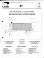
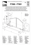
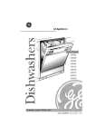
Automazione
esternaper cancellia battente
Externalautamaticopeningsystemfor winggates
Automatizacion
exteriorparapuertasbatientes
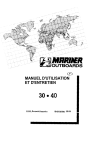
Ca_vi_diqellega.mcn!s...m.ierein!e-rf.u_t!_o-r_ì: W-tingfattttiercslytl'c.tes.,
5x1mm2
5 x lmnr
Cav.idi.jr-llne_n
!€lai_o_ne-m9lsr_e-;
P,awe-rwites-tp-,nplot
2 x 1,5mm2fino a 20 m;
2 x 1,5ntmtup to20 m;
2 x 2,5mm2fino a 30 m.
2x2,5mni' upb3Am
lmpiantotipo
1) Moloriduttore
2) Quadro comando
3) Ricevitoreradio
4) Fotocelluledi sicurezza
5) Selettore a chiave
6) Antenna
7) Lampeggiatoredi movímento
8) Trasmettitoreradio
Standard installation
1) lrreversiblegear motol
2) Controlpanel
3) Radio receiver
4) Safety photocells
5) Key-operatedselector switch
6) Antenna
7) Flashinglight indicatinggate movement
B) Radio transmitter
jqs_l
=Cg.ble.s_-de__ssner.t_ó._n-ni_crq!n!gl.Iu-p!_o.
5x1mmz
eébles,,de,,a.ljmenlac,i_glt-molo_!.1
2 x 1,5 mm2 hasta 20 m;
2 x 2,5 mm2 hasta 30 m
Instalaciontipo
1) Motorreductor irreversible
2) Cuadro de mando
3) Radiorreceptor
4) Fotocélulasde seguridad
5) Selector a llave
6) Antena
7) Lémparaintermitentede movimiento
8) Transmisor
a
o
t:a.
{ù
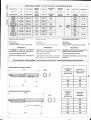
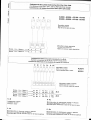
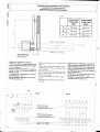
Caratteristiche tecniche - Tecnichalcaracteristics- CaracterÍsticas técnicas
I
l
a
tu
-
MOTORIOUTTORE PESO
GEABMCTOR
(,
2.
uJ
43000
43006
A3024
A3100{R}
43106{R}
A50tx)
450CI6
45024
o
z,
J
4s100{n}
45r06 {R}
NOIIlINAL
AJíìNINT
vvF6HT P{IL4/ER
SUPPLY
MOTORREDUCTOB PESO
J
CORRÉNÎT
NOMINALE
ALIMEIiTAZIONE
ÎJ'
ATIMENTACIOIi
-
POTENZA
POWfR
INTERMITTENZA
tAv0R0
DIJTYCICI,E
RAPPORTO
DI
RIDUZIONE
SPII{TA
REDUCT|OîI
BATIO
PUSH
c0RRtEl'tTC
INTERMITÉNCIA RTTACION
DE
POTENCIA
NOMINAL
TRA8fuO
REOUCCION
10 Kg
230Va.c.
1 , 2A
150W
8,5 Kg
g4V à.c.
104
120w
9,5 Kg
230Va.c.
"1,24
15UW
1|-,24
15CIW
24Va.c.
104
130W
230Va.c"
1 , 2A
1S0W
230V,,a.c.
9,5 Kg
10,5Kg
TRAVE!.
TIMI
CAPACITAR
TITMPO
DE
R:C0RRt00
EMPUJE
c0N0EilsA00R
18s
1 0 pF
2€$
*18 s
5{l%
19s
28s
32*
45s
tf 400 +
3000 N
50o1o
1{l yF
10 pF
**309
32a
ffiú1"
10 pF
45$
D a t i r è l a t i v ia i v a l o r i d i a l i m e n t a z i o n en o m i n a l ee a
condizioni di apèrtura standard:
Dala tefers tù núninàl pawer supply and standard
conditiúns ol aperlu|e;
Datos relativosa los valores de la tension nominal y a
las condicionesde apèrturaesténdar:
(R)Reversibile;
* S e r v i z i oi n t e n s i v o ;
"* Regolabilemediantequadri comando CAME
(R)Reversible;
' Heavy duty cy.:le:
.. Can be adjùsted
usingCAME cúnlroi panels;
(R)Reversible
* Servicioinlensivo;
'*Aiustablemediantelos cuadrosde mando CAME
Deg-c:zroHE:
i
fEMPOCORSA CONDENSATORE
5OYo
1136
11 Kg
t
Dcse.runeÉNi
DEseaLp_teti
- P r o g e t t a t o e c o s t r u i t o i n t e r a m e n t e - Designed and constructed entirely by - Disefradoy fabricado enteramente por
d a l l a C A M EC a n c e l l iA u t o m a t i c iS " p . a . CAME Cancelli Automatici S.p.a
CAMECancelliAutomatici S.p.a
- Grado di prolezione lP 54;
- lP54 protecting rating:
- Gradode protección lP54;
- Garantito24 mesi salvo manomissio- ^ Guaranteedfor 24 months, unlesstam- - Garantizado24 meses,salvo manipuni.
pered with by unauthorized personnel.
laciones.
i
._
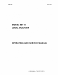
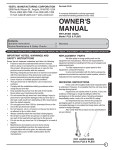
Misured ingombroe lirniti.d'impiego/ Overalldlmensions
anduseÍi.niefs/ Oimen*ionesmóximasy lirnitesde empleo__l
43000/A3006-A31
00/43106-A3024
T
lco
LARGHEZZA
ANTA
WIDTH OF WING
ANCHOHOJA
PESOANTA
WEIGHT OF WII,JG
PESO HOJA
m
KS
2.00
800
2.50
600
3.00
400
LARGHEZZA
ANTA
GEWICHT
ANCHO HOJA
PESOANTA
GEWICHT
PESOHOJA
m
KS
2.00
1000
2.50
800
3.00
600
4.00
500
5.00
400
iRl
+-
45000/A5006-A51
00iA5106-A5024
l
I
i
a
,,..,
I
f : ..2L :f
i
I
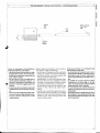
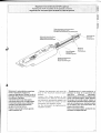
Controlli
i - Generalcantral
J
- Controle*
C'
\2
A.
ut
tlt
2
J
<,
z
ltt
o
z
g
Battutad'arresto
Gate stopper
Tope
+
cl
Y
t %tu
'/a
v
Prima di procedere all'insiallazione
dell'automatismo,controllare:
- che la struttura del cancellosia adeguatamenterobusta, le cernieresiano efficienti e che non vi sia altrito tra
parti fisse e mobili;
- che la misura C non sia superioreal
valoreindicato nellaTab.3, pag. 4. ln
tal casoè necessariointerveniresul
pilastroin modo da raggiungeretale
misura:
- il percorsodei cavi elettrici secondo
le disposizionidi comandoe sicurezzai
- che ci sia una battutad'arresto meccanicoin chiusura(benfissataal suolo) per evitare l'ollrecorsa anta/
motoriduttore.
l_
Cerniera
Hinge
Bisagra
Before beginning installation of the automatîan system, check the following:
- the structureof the gate must be suffìciently
strong; the hinges must function efficiently
and there must be no frlctian between the
moving parts and fixed parts;
- measurementC must not be greater than
the value shown in Tab. 3 (page 4). lf this is
the case, it is necessary to modífy the pillar
sa that this measurementcor-responds;
- the electrical wìring path according to the
position of the control and safety instrumen(5;
- presence of a mechanical gate stop (securely anchored to the ground) in the clased
positian in order to prevent Í.hegate and the
reductian gear from moving beyond the
correct ctose position.
Antes de procedera la instalacióndel
automatismo,controlar;
- la estructura de la puerta sea lo suficientementesólida,las bisagrassean
eficientesy que no haya rozamiento
entre las piezasfijas y aquéllasmóviles;
- la medida C no sea superior al dato
indicado en la Tab.3, pà9. 4. En tal
caso, es necesarioactuarsobreelpilar
hasta alcanzardicha medida;
- el recorrido de los cables eléctricos
según las disposicionesde mando y
seguridad;
- la existenciade un tope para el cierre
(bienfijadoen el suelo)paraevilarque
la hoja/motorreductorlleguemés allé
de lo requerido.
I
J
o
12,
É
ît
u
U'
m
J
(t
z,
UI
o
A30001A3006-A3100iA3106 -43024
APERTURA
OPENING
ABERTURA
A
B
C max
E
mm
mm
mm
mm
90'
130
130
60
7N
120"
130
110
50
720
Pilastro
Pillar
Pilar
J
I
A5000/A5006-A5100/A5106 -45024
APERTURA
OPENING
ABERTURA
90'
'130"
A
B
C max
E
mm
mm
mm
mm
200
200
120
920
2W
140
70
920
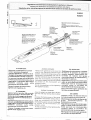
Piastradi fissaggio
Fixing ptate
Placa de f iiación
HxHàHflHIHIH3##
Staffa di coda
Bearbncket
Soportè rasero
Snododi coda
Reariaint
Articulacion
trasera
+
B
+
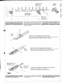
Applicareal pilastro la piastra di fissaggio
con la staffa di coda (fig. 1) rispettando le
quote A e B (Tab.3) tra l'asse della cerniera
e il foro centrale della staffa. La staffa di
coda è dotata di ulteriori forature per varia'
re l'angolo di apertura del cancello.
N.B.:
a u m e n t a n d ol a m i s u r a B d i m i n u i s c eI ' a n golo di apertura con conseguentediminuzione della velocità periferica e aumento
della spinta motore sull'anta. Aumentando
la misura A aumenta l'angolo di apertura
con conseguente aumento della velocità
periferica e diminuzione della spinta motore sull'anta.
Attach the fixing plate and the rear bracket (fig.
1) to the pilar abserv'ingmeasurementA and B
shown in Tab.3, between the hinge pin and the
central hale in the bracket. The rcar bracket is
equippedwithadditionalholes to change the opening angle of the gate"
N.8.:
iÍ nteasurententB ts rncreased. the opening
angle is reduced. This therefore reduces the
peripheratspeed and increasesthe thrust èxerted by the mútor on the gate. lf measttrement
A is increased, the angle af apertLtreis in'
creased, This therefore increases the peripheral speed and reduces the thrust exerted by
the motor on the gate.
Den hinteren Búgel mit der entsprechen'
den Klemmplatte(Abb. 1) unter Einhaltug
der MaBe A und B (Tab.3), und zwar dem
Achsenabstandzwischen zentraler Búgel'
bohrung und Torangelzaplen,am Torpfeiler befestigen. Der hinteren Búgel ist mit
einer Reihe von Bohrungen versehen, um
eine Anderung des Toróffnungswinkelszu
erlauben.
Wichtig!
Beachten Sie bitte, daB bei Erhóhen des
MaRenB der Toróffnungswinkelund demz u f o l g e a u c h d i e p e r i p h a r i s c h eT o r l a u f geschwindigkeitvergróBert und der auf
den Torflúgel ausgeúbte Motorschub red uziert.
I
i
4
I
{
I.l
-J
Spessore
Tllickness
Espesor
Piastradi tissaggio
Fixing plate
Placade Fijación
J
o
rZ
(tt
r!
E
g
J
(5
2
u,
Livellare la staffa
Leve! the baket
Nivelarel soporte
z.
s
J
+j
A cancellochiuso applicaresull'anta la
piastradi fissaggio,accertandosiche la
staffaditesta sia in asse orizzontalecon
la staffadi coda e rispettandola misura
E.
Staffadi testa
Front brackeî
Soportedelantero
With the gate closed, attach the fixing plate
with the front bracket to the gate wing. The
anchor plate must be horízontallyaligned
with the rear bracket and measurement E
must be abserved.
Con la puerta cerrada, incorporar a la
hoja la placa de fijación medianteel soportedelantero,en líneahorizontalconel
soporte lrasero, respetando la medida
E.
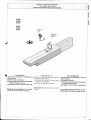
Svitare le due viti di fissaggio del carter ed estrarlo.
Retnove thje two screws which hold the casing in position and remove the rod
Aflojar los dos tornillos de fiiación del eérler y sacarlo.
(,'^
Stelo
Rod
Véstago
Svitare le due viti di fissaggio dello stelo ed estrarlo.
Hentove thje two screwswhich hold the rad in positiortand rcmúve the rod.
Aftojar los dos tornillos de fiiación del véstago y sacarlo.
Dado M8 autobloccante
M8 locknut
TuercaM8 de seguridad
Vitesenzafine
Worm-oear
r"rnirrJ"lnln
é
A
Procedere al montaggio del motoriduttore alle due slatfe'
lnstall the gear motor on the twa brackets
Montar el motorreductor en los dos soportes.
MBxl0
N.B:è consigliabilelubrificare(con gras- N.8; use neulral grease to lubricate the Nota:es aconsejablelubricar(con grasa
so neutro)la vite senzafine e la boccola wormgearand the washer at the mamenl neutra)el tornillo sin fin y la arandelaen
el momentode la instalación.
of installation.
al momentodell'installazione.
I
I
J
o
1Z
I
Gofregamenti
a*esehedeerettronicheTAsr7A4
Cannectionstú theZA,A- ZA4 - ZASa, iM;;;;;;;;;;;;;;r,.A5 rZM.
l
a
tn
rrl
I
at
l
conexisnes
a farariera
etectrónica
zaii i'il'il'ts;i;;
l
(,
J
z,
u,
43000- 43006- A3100- A3106
45000- 45006- A5100 - A5106
o l
z,i
< l
J ]
I
= l
Morsettiera motore
Motar terminat block
Caja de bornes para el motor
Morsettiera scheda elettronica
Tenninal board electrortics
Tablero de bornes tarjeta electrónica
Motore _ li,4otor-Moteur 1 .-*è
Motore - Molor -Moteur 2 -->
jSffegalenri eteilriciai quadricomandoZL14a ZL.t9
to theZLt4 ar ZLte controtpanets
=:?::::connections
Conexiones
eléctricasen los cuadrosOemanOoZL14
ó ZLIS
Ra
l,u1
tel
Morsettiera motore
Motor terminat block
Caja de bornes para el motor
) l
'l
I
t,
l
430?4
45024
Morsettiera quadro comando
Controlpanel teffiina! bloch
Caja de bornes cuadro de mando
\
Motore - Motar - Moteur 1
Motore - Motor - Motew 2
*ttz
Motore - Mator - Moteur 1
*---*-+
Motore - Motor _ Moteur 2
N-M
Collegamento motore
L;annectronto motoÍ
Conexión motor
F' Fa
M.icrointefruttoredi fínec,
N1 Ml 2
M 2 2
Fal Rc1
Fa2 Rc2
z
2
Ral
RaZ
zLl4
Nl Ml
N2 M2
Fat Rcl
Fa2 Rc2
C Ral
C Ra2
zLl9
C
C
R-Rc
Microínteruttore di rallentamento motore
in chiusura
Mtcraswitch-deceleration
of molor ort closui
MicrointerruprordeceteraciélHi;r*;;";
rase de cierre
H-Ha
di rallen
j[?Íix#l,gl,j:r,,*;g"Tr.,""::';:""..aperrura
tw{)ros.wîcn-deceteta,on"i'#frinyr1îninapertura
#[f3'#[??
rvucrotnlerfuptordeceleración
M,icroínterruttore
motoi en la fase de apertura
I.
I
ts---
Regolazionernicrointerruttore$îOP in apertura
Adjustingfire SIOP micraswitchfot the aperturemovement
Regulaciondel microinterru$toide sTOPen:lafasede apertuia
J
o
t2.
À
(t
UJ
E
2
J
(t
z
ut
c}
z
g
J
f(
Slittaazionamentomicrointerrultore
Microswilch actLration runner
Correderaaccionamientomicrointerruptor
Asta porta-microinterruttore
Suppod plate mícroswitch
Chapa porta-microinterruptor
Vite di fissaggio
Fixing scrcw
Tornillode filación
Madrevite
Saew-nut
Tornilloiuerca
Gruppo microinterrutore
Micraswitchutlit
Grupo microinterruplor
Sbloccareil motoriduttoree portare
l'anta in posizionedi apedura
massimadesiderata.Svitare le viti di
fissaggiodel gruppo microinterrutore.
Far scorrereil gruppo
microinterruttoresull'asta porta
microinlerruttorefino a raggiungere
l'inserimento
dello stesso mediante
contattosulla slitta azionamento
gruppo microinterruttore.
Fissareil microinterruttoreagendo
sulle rispetliveviti.
- Release the gearntotarand ntave the
door to the maximum desired open
position.
L o o s e n t h e fi x i n g s c r e w s a f t h e
micraswitch unit" Slide the micraswitch
unit along the microswitclt-supportrod
until ít is inserted by contact an the
microswitch unitactuation runner.
Fix the microswitch by tightening the
respecttve screws.
- Desbloquee el motorreductor y
coloque la hoja en la posición de
apertura
màxima
deseada.
Desenrosquelos tornillos de fijación del
grupo microinterruptor.Haga deslizar
el grupo microinterruptorsobre la
varillaporta-microinterruplorhastaque
este se introduzca por contacto sobre
l a c o r r e d e r a d e a c c i o n a m i e n t od e l
grupo microinterruptor.
Fije el microinterruptor apretando los
tornillos correspondientes.
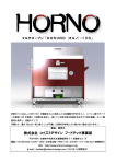
Regolazionemicrointèrruttoridi rallentamentoin aperturae in chiusura
Adiusting the deceleration microswitchesfor apertureand closure
Regulación de los microinterruptores de reducción de la marcha
en las fases de apertura y cierre
o
,:e
CL
î1,
u
u,
l
43024
4,5024
J
C'
z,
rg
o
z.
I
I
J
ts
Batlutad'arrèsto
Gatejafib
Tope
.\
.b
F
t
O
r p
Gruppo microintérruttoredi
rallèntamentoe di stop in
apenufa
Micrzswitch unit far slLrwrrld
and stopping duting apenilV
Grupo microinterruptorde
deceleracióny dè parada
en apenura
Asta pona
mícrointerru$ore
Supponplare
mtcroswttch
Chapa porta
microínterruptor
Supportocavo
CabJef0ber
Soporte paracables
Mícrointerrutîoredi rallentamentoin
chiusura
D erele|ation n iî | os witch for clt]sure
Micrinterruptorde reduccion de la marcha
en cierr€
Vite senza fine
Worm-gear
Tornillosin fin
Slittaazionamento
microinterruttore
MìcroswitchactLralnn {urìner
Correderaaccionamiento
microinlerrupîor
V i t id i f i s s a g g i o
f ixing $rews
Tornillonsde Fijación
Madrevite
screw-nul
Tornilo tuèrca
Madrevite
SLxerv-nul
Tornillotuerca
IN APEBTURA:
Sbloccare il motoriduttoree portare
l'anta in posizione di apertura
massima desiderata,svitare le viti di
fissaggiodel gruppo microinterruttori
di rallentamentoe di stop in aperlura.
Far scorrere il gruppo microinterruttori
sull'asta porta microinlerruttore fino a
raggiungereI'inserimenlodello stesso
mediante contatto sufla slitta
azionamentomicrointerruttore.
Fissareil gruppo microinterrultori
agendo sulle rispettive viti.
IN CHIUSURA:
portare l'anta a non oltre 100 mm dalla
battuta d'arresto in chiusura lpart- È1.
Svilare le viti di fissaggio del gruppo
mrcrotnlerruttoredi rallenlamentoin
chiusura.
Far scorrereil gruppo microinterruttore
sull'asta portamicrointerruitore fino a
r a g g i u n g e r el ' i n s e r i m e n t od e l l o s t e s s o
mediante contalto sulla slitta
azionamenlom icrointerruttore.
Fissare il gruppo microinterruttore
agendo sulle rispettiva viti.
--i
ó l
D T J R I NO
GP E N I N G :
Release fhe geannator ancl move the
wing to the maximunt desired apen
position, unsctew the fixing screwsof the
deceleration microswitches unit ancl the
untt that controls the stop during opening.
Slide the microswitches unit alona the
nticroswitch-supportrod unttl it is inierted
by contact on the nticroswitch unit
actuati?n runner.
Fix the nìcroswitches unit by tightening
the respective screws.
DURING CLOSURE:
move lhe wing to no closer than lA0 mnt
fram the end stap during closure (delail
B)
Unscrew the fixing screws af the group
decelerction microswitch during clasure.
Slide the mlcraswitclt unit alana the
microswitch-supportrod untrl it ts iníerbd
by c0ntact on the microswitch unit
actuatiotl rL!nner.
F'ixthe microswitch unit by tightening the
respective screws.
EN APEBTUFIA:
Desbloqueeel motorreductory coloque
la hoja en la posición de aperlura
m é x i m a d e s e a d a ,d e s e n r o s q u e l o s
tornillos de fijación del grupo
microinterruptores de deceleración y
de parada en apertura.
Hagadeslizarel grupo microinterruptor
sobre la varilla porta-microinterruptor
hasta que este se iniroduzca por
contacto sobre la corredera de
accionamientodel microinterruptor.
Fije el microinterruptor apretando los
tornillos correspondientes.
EN CIERRE:
Coloquela hoja a no màs de 100 mm
del tope de parada de cierre (det. B).
Desenrosquelos tornillos de fijación del
grup0
microinterruptores de
deceleraciónen cierre.
Hagadeslizarel grupo microinterruptor
sobre la varilla porta-microinterruptor
hasta que este se introduzca por
contacto sobre la corredera de
accionamientodel microinterruptor.
Fijeel grupo microinterruptorapretando
los tornillos correspondientes.
z
Sblocco a chiave personalizzala
Personalized key release
Desbloqueo medíante llàve person alizada
J
C}
\2
È
a
l{J
T
2
J
(t
z
UI
43000
43006
43024
45000
45006
45024
o
z
s
J
Chiave
Key
Llave
E?rfr!l
9é;t
f.::r.t
-é-
Per sbloccare
l'operazione di sblocco va efÌettuata a
motore fermo:
1) sollevarelo sportellino;
2) inseriree girare la chiave che istantaneamentesblocca l'anta;
3) spingereo tirare l'antamanualmente.
Sportellino
Access door
Portillo
\ I
18
Releasingthe unit
pertorm thisstep witlt the motot stopped:
I ) raise the access door
2) insertand turn the key.Thegate willbe
released imnediately;
3) puslt or pull the gate ntanually.
para desbloquear
esta operación se debe efecluar con el
motor parado:
1) levantar el portillo;
2) introduciry girar la llaveque enseguida desbloqueala hoja;
3) empujaro tirar la hoja manualmente.
The re-lock the gate, simply inseftand turn
Per bloccarenuovamentel'anta è sufli- the key.
Parabloquearde nuevo la hoja, es suficiente reinseriree girare la chiave
cientevolver a introducir y girar la llave.
-l
o l l
' z ,l I
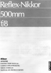
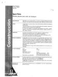
Applicazioneper apertureversol,esterno
Application for o utside aperture
Aplicaciónparaaperturahaciaexterior
a ì l
( a l l
u r i l
I t
l
- l
a i
J ]
(.'l
z. 1
U I
Il
l
43000-3006 45000-5006
3100-3106 5100-5106
3024
5024
o l
z, l
.{t
J i
< l
F I
l
l
A
1 3 0m m
200 m m
B
1 3 0m m
200 m m
E
720 mm
920 mm
Esterno - OLrtsicteÉxlerior
* r---1t
l
)-t),
fntèrno - lnsoide -lnterial
stattasupptementl
Su{-tpIementary b rackeI
Soporte
adicional
- Rilevarele quote A e (Tab.4).
B
- Fissare la staffa di coda
integiandola
con una slaffa supplementaree applíc a r l aa l p i l a s t r o .
- Aprire il cancello
{max 90.}, rilevarela
q u o t a E ( T a b .a ) e f i s s a r e a l l ' a n t a
la
staffa di testa.
- Procedereai collegamenti
elettrici
come da figg. 1 e 2;
- Riposizionaree regolare
il micro inlerruttore di apertura.
-
"A"
the
and,B,, lsee
!!e.as.ure lenght of
Tab 4).
- Attach the rear bracket
together with a
sttpplementary bracket and fasten both
to the calumn.
- Open the gate (maximum g0,')
and measure "E" (see Tab4), then fasten the front
bracket t0 the gate.
- Cannect the wiring as
shown in figs. I
and 2;
- Reposition anrt adjust
the opening microswitch.
- Determinarlas medidas y
A B (Tab.4).
- Fijarel soporte trasero
en el pilar,iras
haberlointegrado por oltro adicional.
- Abrir la puerta (max 90.,),
determinar
la medida E (Tab.4) y filar en la hoja et
soporte delantero.
- Proceder a las conexiones
eléctrícas
de acuerdo con tas tigs. 1 y Z;
- Coloque nuevamentey
regule el mi_
crointerruptor de apertura.
l i
lf ,
'.U\----r
Mi
Y
l
T
\ v_,-1--'------,'
+
i
l
i
i
I
Fis'l
Fig.2
l
r.r M F Fr Rc R Rn
'I
r il
tà iei)àt,
ialÉa)r
,.1L Morsettiera,norore
)e
,
ra
,,l-,,
,!,.
ià[
(t
o
aj o ,r i
+ \U/ ala),Fzik)
---+...
t(al1i '1'"ii V4l
3';:';:1r#i::12r",*.,",-''n'-'-n
i+ l?:l
lz
..r'atr,r--"".*
H
G
r
o
u
n
d
i
u
v
w
i
i
l
l
i
r
Li-; -!;:l llll
Massa LJ
l:::o:r i e r
r
ua vi w
illl
,{
itl
;,-; rl, ,i; J^,
t-,.f
L
,'
!+
-!
i
I
- i i lI
f
ry
l
I
i
i
i i ]
I
i
._l-::,_f.:,---,
fil=ti
,'r-'n5n5nl.J
rú
ÉliLr;
l ' - . - ] L . l r r | - i I 'L
-JL
! t ] l F irn l''
u uv w , i - M ^ ^ rMorore-Moror-Moreurl-*-.)L-r+++1,'
6-,^^.
--/:--N\iffi?
:
r
I
ii
l i , 1 , , ' , j P * ; , T' m :iifi ;i : :IIf li i j - j
l, f-----calaoeÀornescuadrodemando ---*
tJ
i
, ,iillFf,,.t1Hf
, 1,rl
,
-,
I
i
ii
Morore-ny'oror-Moreur2-
S,b
Mz F
îH?-Far Rcz Rz il
(
-l
I
MANUTENZIONE
PERIODIC
A I PERIODICMAINTENANCEIMANTENIMTENTO
PERIODTCO
lr
t
v
l'z
J <
l À
In,
l-
I
t'
2
I
- Lubrificare la vite senza fine e i perni
di
rotazione;
- Controllarele vitidifíssaggio;
- VerificareI'integrita,deicavidi cottegamento,
- Lubricatehe wonn screw and
the rotatino
pins;
- Ceck the clatnpsscrews;
- Ceck the connxtion cable's soundness.
o
z.
- Lubriqueel tornillo sin fin y los pernos
$J
de
rotación;
- Controlelos tornillos de sujeción;
o
z,
- Controle el estado de los cables
de co- s
J
nex6n.
É
t
I
L _ . _
L
iK
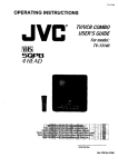
DICH|ARAZ|ONE
oel pnÉnnlffi,r.rrE
Data de!tx p11,5sn1s4,ctuaraz;onp
t'lxd'dzu'te u/')
6). tzloul
12;;gg1
lnolke, dich jara cho il/t
Í,rodano,,i, ,aù
della presenle dichrarazione, sono
cosîtutt/ net ilspotiú
(,,n,n*,",,
del le sègue
delle
srro!Fnt)
^^-,,^ a,,"-_..,.î.!j!,
n lt {yinct
patí notrne
nr"r,ín,zzttte
I Rappreseillanti{leila
C A M EC a n c e l t A
i 0tomaticS
i .p.A.
via f',,|arîrri
deilaLiberiè,lat
31o3oDoss.inili Casi.ir. Treviso lTALylel
í r 3 9 )0 4 P 24 9 4 0 l a x l + 3 9 j0 4 Z A4 9 4 1
rnteriel:!r,r!wcane_l(_e_rnaji:
;nÍoliicatrieI
E f ' l2 9 2 i * H í È1 , , 82 ,
EN 12453
EN 12445
Ér'.t
60335. 1
Ehi60204. 1
Éf'5
i 0 0 8 1- 1 É 2
El'j50082.1É2
DtchiaeDa sailola prcptia respansabttttàche
i/!l oro(tottù/,!tjètlonrinaîo.,i
Íi o rnilz,r cEt
fir,. .u.t'.t.,
cr,
ùtAaa.i ùAF,o
:-at
L-..,r'.1L4.
.rÀÈ :itw .-al
u ..,.rits x.:
5,Or.HÈiz^
N E a ì i t A F e A H E T i : c f t in !
b:cL'ìiZZ?ì
DEi ft4Oci
!sri
trofi!sircrj
tlAF:O
CouirAi lir,LiT! EiE Í ì io^rariN!l
{::A
CoMirAi B,LiTÀ EiE i I so[iariN! I ia
A.
AVVERTENZA IhIPARTANTE!
E
mettercin seruízioiri ptodo{io/i,oggettodeila prèsente
tJlcl|eraziotje.piln1adcjl
-vietaio
&Ítpiotaùiento
è,,oincerporanènta. ,n totajà contototità aIi
aìi[urirliíoan
air"ntun
lr!acchrìe 98,i3VCE
. . sorìo ccnfoffiti eilct (Jispasi:pni tegislative
Nazrcna!i ctte truspongoa(, le seguèùti
Ditelilve
Ca n1L!n tta n e (dove spect ficatane nîe
ap pt ttabtl |).
l,Irrnatlei Rapprctsentarìli
HE SPONSAT}
iL E r.ECNICO
stg cannii,aUJa'n-"
i
., ,
,
;,.,
.,..ti
lJ nÈrr vA i,4^c.ilN: gBt3TiCE
D|FErîiva f]alsa f IN-:roN[ 73./23,/{]ÉÈ,
93l6BiCE E
DrBF':,vA (lor,tFAr6 ra Et ErtÈiìMA!ilirca
ti9/33€;/CEF - g}i:i 1 iC)EÉ
LrrFEr,vnR&lTE 1999/SiCÉ
I).Òa\i ft ìé\7i d : I tu t rJa i i c h ú
PRÈstaE^ttE
t'g Peolu Me1y2zt'
t,
)-^
.
<' <'*
^.-
\iDhe úèì
MAN
uFAcruRER;S
oecrffi
r,r
z,,cE
Encrosedwiththetechnicardocumentatior
lthe origiraìnfirGJ1l^ration
is avairabre
on rcquest)
The representalives of
o"t"ottn"Gffi]lfffrlffit
Also, they futthermorerepresentand watrant
that theproduct/s that are the suqectot the present
Dectaratíon are manutactured in the respect
ot tne tio*iij
iaìniìràir-irea
prorisiors,
Èli 292 Fxnr1 ^rrir2
N 4 a o r j t N E lì ; 5 n t I f y .
FN 12453
lritrt;:trirDI, icfyrùjIFciAi aNo crf
F B a t i ] i j t fj i t u F ( ì i 1 { ! r s f , 1 s
EN 124,15
l',',r ,;,ar ,:',.r.,F;.a. a.t.
riLl
..
rr_ vL.,.;,...,r.
EN 603Jì5-1
ùt !:r ," ,,::^r,ar,..t..c. o
(1L .L.
EN 60204- 1
l ' . 4 1 , t: , , r E F u s A a r .
EÀi500B1. I Arf 2
Ei.Er-rÉoMActEtrc CovreletL,t
y
ÈN 5008? , 1 ^,irra
Eit,:.rltr,lli:;le
i0 (loupaT ptL rr
CA&tECanceili Automatici S.p.A.
viarÀ4itrlr.i
dellaLitrerta 15
31(i30a)osson.li Casier- Treviso- lTAl.y
lel ir39) 04224940- lax (+39)0,i224941
Interiret:
!!v/!vcame.il É_nlaii:
[email protected]
Hereby declare, under theî own rcspons ibitíty,
that the product/s cailed
IMPORÍANî CAUTION!
l:i::1t!!!en to
pnducî1.sîhat
ar_^îhe subjectoi ihis cieîiaratian{,ercreconlpteîng
arid,
or !ncatporating Tirket/use
them in total cofttptiance with tne
fjrovisions ot Uacniiiirr) nirective g|l:t7.i(:E
... compry wtth the ltalian National Legal prcvisions
lollowing Communíty Directives (where
specíficatty
Signalurcs of the if eptese ntatir.és
that transpose 'the
'
appticaòiis1.:-
TECHNIl}AI MATNAGER
Mr. Giànrt Micltetan
I
i
il.
i
í i , i ., ! : ' i . . "
1 { . 1 .- . .
Idactsr\É?,/DrF:c-lrvE99,,37lCiE
Low VoLiAGEDtHÉoi,v: 7il2-llEEC ,
33159,16gg
La-:j&t.d::lrIr,:: CoUt,lr,iii ru Dtfirr::Irr gSl:ì30,/[taC .
92/31/ÉEC
R&fîÈ DrqÈtrirr 19_o9i
atlcF
MANAGÍNG DIRECTOfr
Mt. Paolo l,'leluzzÒ
"i" ú "":t'i:::::--**
a.)il tte ptù(trît, t5 ,àvr.t.jb!ìon îtttiest
:5-p:131!a133!lent;lo
DEC
DEL FABRICANTE
onestad'ponibreprcwapeticrcn)
LosRepresentantes
dela compaòia
CAMEcancelriautomaticis.D_A.
via L4ariiri(iejlú L.ii,erta 15
EN29r?aFrEr"i2.
ÈNt124s3
[-:N12445
310.1,)Dossondic;iierltrevrso-ttnL,y
1er(.i39)04214940 .ìo* r*sòj joze or*,
,rrcr cr. !!s/!vÉamei, - a-ni,i, ,nlo-o"ur"
,t
Decta^nbarosuresponiaoi,aaolàeureproducto/sdenominado/s...
Eli33;31,1
EN5()081-lriì
EN50082,rE2
4 3 0 0 0 . A 3 0 0 6 .A 3 1 0 0 .A 3 i 0 6 . A 3 0 2 4 .
A 3 12 4
A 5 0 0 0 .A 5 0 0 6 .A S 1 0 0 .A 5 1 0 6 .A 5 0 2 4 .
A5124
D001. H3000. LOCKB1. LOCK82
tassisuientes
,; ::J:::L:;:,Xi,!;::i:f*,!:z:í::lr::,:;::;:";î,:::,que trasponen
AVVE RÍE NZA IMPOfr TANî E!
Estàprohibidonacq uso dÈ el,,(,stiroduLlo,,s.objetúCe
ia presenîe,leclaea.iórì an*súe tlotrlptetaia
s y,rùutcorpÒtarlo./s
eù iùiai Lyntùrnidaú a lztsdisposicionèsde ià fri,:""iiàiju
llnqriFas eBiz,CE.
FirfrÉ iie los Represeilanîes
RESPA NS/\B i.E TECù1I CO
St (;ianni ttichìeian
Drnecivr :,: Mi.ì lrA:ì9B/37l,tlF
"., '" . B- ,I r .. .,íì
2 r . C L b e . ; 6 d C EE
P
iilll -''ì ;^Îi;]nìr u, F
'-
re"ffiot
Losptoductos
obieto
de estadecraraciónestàn
rabricados
rcspetandoiassiguientes
normas
amontzadas:
:' ó ,c' a 8e'336
cEÉ (2,r cÉL
,l
/
ii
,;ìii.,,t'!,:.1i:...
lH)clYSn
li:',]J f,i:j";:1",,#Íl
"TlÍ:,iJló.,,1"8,,,'lf
;:lr;";l;;1,,,r;;ì
":;
Alj ta!3
.iccepteú
teyi:::":i:\'it!(:a
cli.tckècj
Îor aîv
tu!i1
etr.t
IN]]ì Ttít1t{.A
dè túst)ttcluctùs estàdisponibteprevia penaon
\ijtt)
iiastjttf]!
nn
];èbih!j1 ):,
-ii:::'
SilltM^
aìLrAJlA
I B 0 ù2 s s s t 0
lV$
w w w ,c a m e . i t
E"[email protected]
C A M EC A N C E L L A
I U T O I , / A T I CSI , r ] . A .
Dossoi,r
oi C,isren(TREVISO)
J(+39)0422 4940 5(+39)042249a1
L
- -*-L'*'ei "::':íl'"'i:::*
;:,,....-...
iììiiìill:;iii:i:.Ìii!ìr:i!!):1.;t:diiti:lii::+iÈuiiili;:iiÌ;trÌjii!ì!titiiiiijij::iiii:tri:iìlf,irìì::ji::
N u n r n oV r n x
PRESID[:NrE'
Sr. paoiD lient!z;t)
lodos
lo$ dato:. s o n a n c o n t l o l a d o
con lt marrma atÈnrron
l{o
olrslante
no nos r e s p o n s e b ' t t z a m o s q e
los postbles errores u
oftlt9tone5.
: : : 1 , 1 r r r _ : : : i l l ì - :-:r : i : : 1 .
l::1r:i::: ::.r:.. :::: ::::.1r|i::r.
.'coiry'ro
M(Mr)"o"'*o"i;;-- ù;;;
ilffi;
:1Y5*lT:-i'?3S3;*'
.;__-i+39)0a -2s490gBB
.:l::""
r 4
astsosoi-J;
orru5u5
r{r33)
t o ù / v01
f ! (ir.s3ì",,,
+33) 0l 4
4€rrnÀn^
6130500
CAMESUOS.R.L
oE-'dj,?lrllffi?lài
i^i;'i;;'àq+ss s iissioeiTtlolîsi.if,'#'îî;a;uró
CAME(AMEHICA)LLC
. :..r:.tr
-,,. -- t tAMr(FL) "origy?rJ,r-,. ,.. -.;r serrerceer
{BERLTN)l
I (*t) sossssopztÉ.1i-iiaÀs
iJlli * saeeasen
Ér (*ae)0sisesesscB
i::::t
CAME AUTOMATTSMOS
S.A
_. MADRTD CAMEpL
- .._:
J {+34)oer s2gsoos -f ;{i4tiai
CAMFBELCì'UM
NU. SA
ds;;A
LESSINES
J- {*32)068 33a014 É! ('32) o$eiàsilé
SP.ZO0____
WARSZAWAJ
iìài oez 836s076 E (,4s) ozz Bg6ee2o
C A M E U N I T E D K I N G D O M L ' T.D. N O T T I N G H A M J
iloiu.,,un r.roouoÈl (+44}0115e210431