1
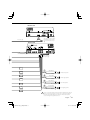
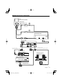
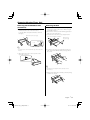
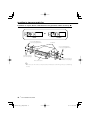
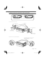
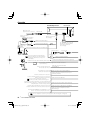
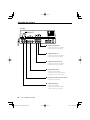
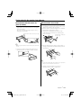
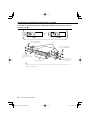
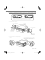
KVT-719DVD
KVT-739DVD
MONITOR WITH DVD RECEIVER
INSTALLATION MANUAL
MONITOR CON RECEPTOR DVD
MANUAL DE INSTALACIÓN
© B54-4513-00/00 (KV/RV)
B54-4513-00_00_English.indd 1
07.1.9 7:15:02 PM
Accessories
1
0
..........1
2
..........4
!
..........1
3
..........4
@
..........1
..........2
4
..........1
5
..........1
6
..........2
7
..........4
8
..........4
9
..........2
2 |
KVT-719DVD/KVT-739DVD
B54-4513-00_00_English.indd 2
07.1.9 7:15:03 PM
Installation Procedure
1. To prevent a short circuit, remove the key from the
ignition and disconnect the - battery.
2. Make the proper input and output wire connections for each unit.
3. Connect the speaker wires of the wiring harness.
4. Connect the wiring harness wires in the following
order: ground, battery, ignition.
5. Connect the wiring harness connector to the unit.
6. Install the unit in your car.
7. Reconnect the - battery.
8. Press the reset button.
2WARNING
• If you connect the ignition wire (red) and the battery wire
(yellow) to the car chassis (ground), you may cause a short
circuit, that in turn may start a fire. Always connect those
wires to the power source running through the fuse box.
• Do not cut out the fuse from the ignition wire (red) and the
battery wire (yellow). The power supply must be connected
to the wires via the fuse.
¤
• If the power is not turned ON (or it is ON, but will be OFF
immediately), the speaker wire may have a short-circuit
or touched the chasis of the vehicle and the protection
function may have been activated. Therefore, the speaker
wire should be checked.
• If your car’s ignition does not have an ACC position, connect
the ignition wires to a power source that can be turned on
and off with the ignition key. If you connect the ignition
wire to a power source with a constant voltage supply, as
with battery wires, the battery may die.
• If the console has a lid, make sure to install the unit so that
the faceplate will not hit the lid when closing and opening.
• If the fuse blows, first make sure the wires aren’t touching
to cause a short circuit, then replace the old fuse with one
with the same rating.
• Insulate unconnected wires with vinyl tape or other similar
material. To prevent a short circuit, do not remove the caps
on the ends of the unconnected wires or the terminals.
• Connect the speaker wires correctly to the terminals to
which they correspond. The unit may be damaged or fail to
work if you share the - wires or ground them to any metal
part in the car.
• When only two speakers are being connected to the
system, connect the connectors either to both the front
output terminals or to both the rear output terminals (do
not mix front and rear). For example, if you connect the +
connector of the left speaker to a front output terminal, do
not connect the - connector to a rear output terminal.
• After the unit is installed, check whether the brake lamps,
blinkers, wipers, etc. on the car are working properly.
• Mount the unit so that the mounting angle is 30° or less.
English |
B54-4513-00_00_English.indd 3
3
07.1.9 7:15:04 PM
Connection
Monitor/Player unit
USB device (commercially
available)
USB connector
Ignition key
switch
Accessory @
Wiring harness
(Accessory 2)
Car fuse box
ACC
Ignition wire (Red)
The cable (Accessory 3) is
fixed with a chassis using
harness band (Accessory
@).
Battery wire (Yellow)
Car fuse box
(Main fuse)
FUSE ( 5A )
Ground wire (Black) - (To car chassis)
Antenna Cord
A
+
Do not connect.
Accessory 4
–
Battery
Connect to the vehicle's parking brake
detection switch harness using the
supplied relay connector.
Battery wire (Yellow)
FUSE ( 10A )
A
Parking sensor wire (Light Green)
PRK SW
Ground wire (Black) - (To car chassis)
For the sake of safety, be sure to connect the parking sensor.
To vehicle's reverse lamp harness
To car light control switch
To steering remote
Connect to the terminal that is grounded when either
the telephone rings or during conversation.
To connect the Kenwood navigation system,
consult your navigation manual.
Depending on what antenna you are using,
connect either to the control terminal of the motor antenna, or to the
power terminal for the booster amplifier of the film-type antenna.
When using the optional power amplifier,
connect to its power control terminal.
To "EXT.AMP.CONT." terminal of the amplifier
having the external amp control function.
Reverse sensor wire (Purple/White)
Dimmer control wire (Orange/White)
Steering remote control input (Light Blue/Yellow)
Mute wire (Brown)
Motor antenna control wire (Blue)
Power control wire (Blue/White)
External amplifier control wire (Pink/Black)
If no connections are made, do not let the cable come out from the tab.
4 |
KVT-719DVD/KVT-739DVD
B54-4513-00_00_English.indd 4
07.1.9 7:15:05 PM
Receiver unit
Accessory @
Accessory 3
Receiver unit
The cable (Accessory 3) is
fixed with a chassis using
harness band (Accessory
@).
FM/AM antenna input
Wiring harness
(Accessory 1)
ILLUMI
FRONT L
REVERSE
White/Black
REMO.CONT
FRONT R
White
REAR L
ANT CONT
+
To front right speaker
Green/Black
Green
REAR R
P. CONT
To front left speaker
Gray/Black
Gray
MUTE
+
+
To rear left speaker
Purple/Black
Purple
+
To rear right speaker
EXT. CONT
If you connect the ignition wire (red) and the battery wire (yellow)
to the car chassis (ground), you may cause a short circuit, that in
turn may start a fire. Always connect those wires to the power
source running through the fuse box.
English |
B54-4513-00_00_English.indd 5
5
07.1.9 7:15:07 PM
System Connection
Receiver unit
■ Front Preout
• Audio left output (White)
• Audio right output (Red)
■ Rear Preout
• Audio left output (White)
• Audio right output (Red)
■ Subwoofer Preout
• Audio left output (White)
• Audio right output (Red)
■ Audio/Visual input
• Visual input (Yellow)
• Audio left input (White)
• Audio right input (Red)
■ Rear View Camera Input
• Visual input (Yellow)
■ Audio/Visual Output
• Visual output (Yellow)
• Audio left output (White)
• Audio right output (Red)
6 |
KVT-719DVD/KVT-739DVD
B54-4513-00_00_English.indd 6
07.1.9 7:15:09 PM
Optional Accessory Connection
iPod
(commercially available)
iPod
AUDIO IN
KCA-iP300V
(Optional Accessory)
Audio Input
Resistance-free stereo type mini
plug (3.5Ф)
iPod
VIDEO IN
Audio Output
(Black)
Visual Input
Resistance-free mini plug (3.5Ф)
Monitor/Player unit
Visual Output
(Yellow)
USB terminal
USB terminal
Receiver unit
Accessory 3
Connection cable
(Included in the Navigation System)
Connection cable
(Included in the Disc changer)
Disc Changer etc.
(Optional Accessory)
Navigation System
(Optional Accessory)
TV Tuner
(Optional Accessory)
TV ANTENNA INPUT
TO MONITOR UNIT
Connection cable
(Included in the TV tuner)
English |
B54-4513-00_00_English.indd 7
7
07.1.9 7:15:10 PM
Installation for Monitor/Player Unit
Firewall or metal support
Screw (M4X8)
(commercially available)
Bend the tabs of the mounting
sleeve with a screwdriver or similar
utensil and attach it in place.
Self-tapping screw
(commercially available)
Metal mounting strap
(commercially available)
Accessory 5
Make sure that the unit is installed securely in place. If the unit is unstable,
it may malfunction (eg, the sound may skip).
Installation for Receiver Unit
1. Attach the installation brackets 9 to the sides of
the receiver unit using the sems bolts 7.
Installation brackets
(Accessory 9)
Sems bolts (M4 × 8 mm)
(Accessory 7)
2. Use the tapping screw 8 to secure the receiver
unit to the audio board.
8 |
Tapping screw (ø4 × 16 mm)
(Accessory 8)
KVT-719DVD/KVT-739DVD
B54-4513-00_00_English.indd 8
07.1.9 7:15:11 PM
Removing Monitor/Player Unit
Removing the Hard Rubber Frame
(escutcheon)
1. Engage the catch pins on the removal tool 6 and
remove the two locks on the lower level.
Lower the frame and pull it forward as shown in
the figure.
Removal Tool (Accessory 6)
Removing the Unit
1. Remove the hard rubber frame by referring to the
removal procedure in the section <Removing the
Hard Rubber Frame>.
2. Remove the Hex-head screw with integral washer
(M4 × 8) on the back panel.
3. Insert the two removal tools 6 deeply into the
slots on each side, as shown.
Removal Tool
(Accessory 6)
Catch
Lock
⁄
• The frame can be removed from the top side in the same
manner.
4. Lower the removal tool toward the bottom, and
pull out the unit halfway while pressing towards
the inside.
2. When the lower level is removed, remove the
upper two locations.
⁄
• Be careful to avoid injury from the catch pins on the
removal tool.
5. Pull the unit all the way out with your hands, being
careful not to drop it.
English |
B54-4513-00_00_English.indd 9
9
07.1.9 7:15:12 PM
Installing in Japanese-made Cars
Installation on Toyota, Nissan or Mitsubishi Car using Brackets at Holes shown by "●"
or
Accessory 0 (M5x6mm)
or Accessory ! (M5x7mm)
Car Bracket
Accessory 0 (M5x6mm)
or Accessory ! (M5x7mm)
Screws (included in
audio unit package)
Audio unit or others
Screws (included in
audio unit package)
⁄
• Do not use your own screws. Use only the screws provided. If you use the wrong screws, you could damage
the unit.
10 |
KVT-719DVD/KVT-739DVD
B54-4513-00_00_English.indd 10
07.1.9 7:15:13 PM
Installation on Toyota Car using Brackets at Holes shown by "●"
or
When using the bracket shown above, you cannot use screws at two holes of
the right and left unit sides.
1. Mount the bracket at each side.
Accessory 0 (M5x6mm)
Car Bracket
Accessory 0 (M5x6mm)
Screws (included in
audio unit package)
Screws (included in
audio unit package)
2. Bend each end of case to fix the bracket.
Use a flat-blade screwdriver or pliers, and bend
each case tab into the hole of installation
bracket to fix the bracket.
English |
B54-4513-00_00_English.indd 11
11
07.1.9 7:15:13 PM
Accesorios
1
0
..........1
2
..........4
!
..........1
3
..........4
@
..........1
..........2
4
..........1
5
..........1
6
..........2
7
..........4
8
..........4
9
..........2
12 |
KVT-719DVD/KVT-739DVD
B54-4513-00_00_Spanish.indd 12
07.1.9 7:16:04 PM
Procedimiento de instalación
1. Para evitar cortocircuitos, retire la llave de
encendido y desconecte la batería -.
2. Realice en forma adecuada las conexiones de
cables de entrada y salida para cada unidad.
3. Conecte los cables de los altavoces del mazo de
cables.
4. Conecte los cables del mazo en el siguiente orden:
tierra, batería, encendido.
5. Conecte el mazo de cables a la unidad.
6. Instale la unidad en el automóvil.
7. Reconnect the - battery.
8. Haga una reposición del sistema (reposición).
2ADVERTENCIA
• Si conecta el cable de encendido (rojo) y el cable de la
batería (amarillo) al chasis del vehículo (tierra), puede
ocasionar un cortocircuito, que puede provocar un
incendio. Conecte siempre esos cables a la fuente de
alimentación que pasa por la caja de fusibles.
• No desconecte el fusible desde el cable de encendido (rojo)
ni el de la batería (amarillo). El suministro de alimentación
debe estar conectado a los cables a través del fusible.
¤
• Si no se activa la alimentación (o si está activada, pero se
desactiva inmediatamente), es posible que el cable de
altavoz tenga un cortocircuito o que esté en contacto con
el chasis del vehículo y la función de protección se haya
activado. Por lo tanto, es necesario revisar el cable e altavoz.
• Si el encendido de su coche no dispone de posición
CA, conecte los cables de encendido a la fuente de
alimentación que pueda activarse y desactivarse con la
llave de encendido. Si conecta el cable de encendido a
una fuente de alimentación con un suministro de voltaje
constante, como con los cables de la batería, la batería
puede agotarse.
• Si el panel de mandos tiene una tapa, asegúrese de instalar
la unidad de tal forma que la placa frontal no golpee la tapa
cuando se abra o se cierre.
• Si se funden los fusibles, asegúrese primero de que los
cables no están en contacto pues pueden ocasionar un
cortocircuito, luego reemplace el fusible dañado por uno
nuevo que tenga la misma potencia de servicio.
• Aísle los cables desconectados con cinta de vinilo u otro
material similar. Para prevenir los cortocircuitos, no quite las
tapas de los cables o terminales desconectados.
• Conecte correctamente los cables de altavoz a los
terminales que corresponden. La unidad se puede dañar o
no funcionar si comparte los cables - o los conecta a tierra
a cualquier parte metálica del vehículo.
• Cuando solamente se conectan dos altavoces al sistema,
los conectores se deben conectar ya sea a los terminales de
salida delanteros o a los terminales de salida traseros (nunca
mezcle los delanteros y los traseros). Por ejemplo, si realiza
la conexión del conector + del altavoz izquierdo a un
terminal de salida delantero, no conecte el conector - a
un terminal de salida trasero.
• Después de haber instalado la unidad, asegúrese de que las
luces de freno, los intermitentes, los limpiaparabrisas, etc.
del automóvil funcionan correctamente.
• Instale la unidad en un ángulo de 30˚ o menos.
Español |
B54-4513-00_00_Spanish.indd 13
13
07.1.9 7:16:05 PM
Conexión
Pantalla/Reproductor
Dispositivo USB
(disponible en el comercio)
Llave de encendido
interruptor
Caja de fusibles
del vehículo
ACC
Terminal USB
Accesorio @
Mazo de conductores
(Accesorio2)
Cable del encendido (Rojo)
Un cable óptico (Accesorio 3)
está fijo a un chasis mediante
una banda preformada
(Accesorio @)
Cable de la batería (Amarillo)
Fusible del
vehículo caja
(Fusible
Cable a tierra (Negro) - (Al chasis del automóvil)
principal)
FUSIBLE ( 5A )
Cable de antena
A
+
No conectar.
Accesorio 4
–
Batería
FUSIBLE ( 10A )
Conecte al cableado del interruptor de
detección del freno de estacionamiento
del vehículo utilizando el conector relé
suministrado.
Cable del sensor de estacionamiento (Verde claro)
PRK SW
Cable de la batería (Amarillo)
A
Cable a tierra (Negro) - (Al chasis del automóvil)
Por razones de seguridad, asegúrese de conectar el sensor de
estacionamiento.
Al mazo de cables de la luz de
marcha atrás del vehículo
Al interruptor de control de
iluminación del automóvil
Al mando a distancia de la dirección
Conecte al terminal puesto a masa ya sea al sonar el
teléfono o durante la conversación.
Para conectar el sistema de navegación
Kenwood, consulte el manual de navegación.
En función de la antena que utilice, conéctelo al terminal de
control de la antena del motor o al terminal de potencia para
el amplificador de la antena de tipo película.
Cuando utilice el amplificador de potencia opcional,
conéctelo al terminal de control de potencia respectivo.
Al terminal "EXT.AMP.CONT." del amplificador con la
función de control del amplificador externo.
Cable del sensor de marcha atrás
(Violeta/Blanco)
Cable de reductor de luz (Naranja/Blanco)
Entrada del mando a distancia de la dirección
(Azul Claro/Amarillo)
Cable de silenciador (Marrón)
Cable de control de la antena del motor (Azul)
Cable de control de alimentación (Azul/Blanco)
Cable de control del amplificador externo
(Rosado/Negro)
Si no se efectúan las conexiones, no deje que el cable sobresalga de la lengüeta.
14 |
KVT-719DVD/KVT-739DVD
B54-4513-00_00_Spanish.indd 14
07.1.9 7:16:05 PM
Receptor
Accesorio @
Accesorio 3
Receptor
Un cable óptico (Accesorio 3)
está fijo a un chasis mediante
una banda preformada
(Accesorio @)
Entrada de antena FM/AM
Mazo de conductores
(Accesorio1)
ILLUMI
FRONT L
REVERSE
Blanco/Negro
REMO.CONT
FRONT R
Blanco
REAR L
ANT CONT
+
Al altavoz delantero derecho
Verde/Negro
Verde
REAR R
P. CONT
Al altavoz delantero izquierdo
Gris/Negro
Gris
MUTE
+
+
Al altavoz trasero izquierdo
Púrpura/Negro
Púrpura
+
Al altavoz trasero derecho
EXT. CONT
Si conecta el cable de encendido (rojo) y el cable de la batería
(amarillo) al chasis del vehículo (tierra), puede ocasionar un
cortocircuito, que puede provocar un incendio. Conecte siempre
esos cables a la fuente de alimentación que pasa por la caja de
fusibles.
Español |
B54-4513-00_00_Spanish.indd 15
15
07.1.9 7:16:08 PM
Conexión del sistema
Receptor
■ Salida previa delantera
• Salida izquierda de audio (Blanca)
• Salida derecha de audio (Roja)
■ Salida previa trasera
• Salida izquierda de audio (Blanca)
• Salida derecha de audio (Roja)
■ Salida previa del subwoofer
• Salida izquierda de audio (Blanca)
• Salida derecha de audio (Roja)
■ Entrada Audio/Visual
• Entrada visual (Amarilla)
• Entrada izquierda de audio (Blanca)
• Entrada derecha de audio (Roja)
■ Entrada de la cámara de visión trasera
• Entrada visual (Amarilla)
■ Salida Audio/Visual
• Salida visual (Amarilla)
• Salida izquierda de audio (Blanca)
• Salida derecha de audio (Roja)
16 |
KVT-719DVD/KVT-739DVD
B54-4513-00_00_Spanish.indd 16
07.1.9 7:16:09 PM
Conexión de accesorios opcionales
iPod
(disponible en el comercio)
iPod
AUDIO IN
KCA-iP300V
(Accesorio opcional)
Entrada de audio
Toma mini tipo estéreo sin
resistencia (3,5Ф)
iPod
VIDEO IN
Salida de
audio (Negro)
Entrada visual
Toma mini sin resistencia (3,5Ф)
Pantalla/Reproductor
Salida visual
(Amarillo)
Terminal USB
Terminal USB
Receptor
Accesorio 3
Cable de conexión
(Incluido en el cambiador de
discos)
Cable de conexión
(Incluido en el sistema de navegación)
Cambiador de discos, etc.
(Accesorio opcional)
Sistema de navegación
(Accesorio opcional)
Sintonizador de TV
(Accesorio opcional)
TV ANTENNA INPUT
TO MONITOR UNIT
Cable de conexión
(Incluido con el sintonizador de TV)
Español |
B54-4513-00_00_Spanish.indd 17
17
07.1.9 7:16:10 PM
Instalación para el monitor/unidad de reproductor
Muro cortafuego o soporte de
metal
Tornillo (M4X8)
(disponible en el comercio)
Doble las lengüetas del manguito
de montaje con un destornillador
o herramienta similar y fíjelo.
Tornillo autorroscante
(disponible en el comercio)
Correa de montaje metálica
(disponible en el comercio)
Accesorio 5
Asegúrese de que la unidad está instalada en forma segura. Si la unidad está en una posición
inestable, es posible que no funcione correctamente (por ejemplo, el sonido puede interrumpirse).
Instalación para la unidad receptora
1. Instale los soportes de instalación 9 a los lados de
la unidad escondida utilizando los pernos 7.
Soportes de instalación
(Accesorio 9)
Pernos sems (M4 × 8 mm)
(Accesorio 7)
2. Utilice el tornillo de rosca cortante 8 para asegurar
la unidad escondida al panel de audio.
18 |
Tornillo autorroscante (ø4 × 16 mm)
(Accesorio 8)
KVT-719DVD/KVT-739DVD
B54-4513-00_00_Spanish.indd 18
07.1.9 7:16:12 PM
Desinstalación de monitor/reproductor
Desinstalación del marco duro de
goma (escudete)
1. Enganche la uña en la herramienta de extracción
6 ay retire los dos cierres provistos en dos lugares
de la parte inferior.
Tal como se muestra en la figura, baje el marco y
extráigalo hacia adelante.
Herramienta de extracción (Accesorio 6)
Desinstalación de la unidad
1. Extraiga el marco duro de goma siguiendo el
procedimiento de extracción descrito en la sección
<Extracción del marco duro de goma>.
2. Quite el tornillo de cabeza hexagonal con arandela
integral (M4 × 8) del panel posterior.
3. Inserte las dos herramientas de extracción 6
profundamente en las ranuras de cada lado, tal y
como se muestra.
Herramienta de extracción
(Accesorio 6)
Uña
Cierre
⁄
• El marco puede extraerse desde el lado superior del mismo
modo.
4. Mueva la herramienta de extracción hacia abajo, y
extraiga la unidad hasta la mitad mientras presiona
hacia adentro.
2. Después de extraer la parte inferior, libere de la
misma manera los dos lugares del lado superior.
⁄
• Procure evitar cualquier tipo de accidente con los pasadores
de bloqueo en la herramienta de extracción.
5. Termine de sacar la unidad con las manos,
prestando atención para no dejarla caer.
Español |
B54-4513-00_00_Spanish.indd 19
19
07.1.9 7:16:12 PM
Instalación en automóviles fabricados en Japón
Instalación en coches Toyota, Nissan o Mitsubishi utilizando soportes en los orificios
mostrados en "●"
o
Accesorio 0 (M5x6mm)
o Accesorio ! (M5x7mm)
Abrazadera
Accesorio 0 (M5x6mm)
o Accesorio ! (M5x7mm)
Tornillos (incluidos en el
paquete de la unidad de
audio)
Unidad de audio y otros
Tornillos (incluidos
en el paquete de la
unidad de audio)
⁄
• No utilice sus propios tornillos. Utilice únicamente los tornillos suministrados. Si utiliza tornillos erróneos,
podría dañar la unidad.
20 |
KVT-719DVD/KVT-739DVD
B54-4513-00_00_Spanish.indd 20
07.1.9 7:16:13 PM
Instalación en automóvil Toyota utilizando soportes en los orificios mostrados en "●"
o
Cuando se utilice la abrazadera indicada anteriormente, no es posible utilizar
tornillos en los dos oficios de los lados derecho e izquierdo de la unidad.
1. Monte la abrazadera a cada lado.
Accesorio 0 (M5x6mm)
Abrazadera
Accesorio 0 (M5x6mm)
Tornillos (incluidos
en el paquete de la
unidad de audio)
Tornillos (incluidos
en el paquete de la
unidad de audio)
2. Doble cada extremo de la cubierta para fijar el
corchete.
Use un destornillador plano-de pala o unos alicates
y doble la pestaña de la cubierta una vez dentro del
agujero del corchete de instalación para fijarlo.
Español |
B54-4513-00_00_Spanish.indd 21
21
07.1.9 7:16:14 PM
B54-4513-00_00_Spanish.indd 22
07.1.9 7:16:14 PM
B54-4513-00_00_Spanish.indd 23
07.1.9 7:16:14 PM
B54-4513-00_00_Spanish.indd 24
07.1.9 7:16:14 PM


![KVT-729DVD - [::] Kenwood ASC](http://vs1.manualzilla.com/store/data/006225897_1-b17f9c5511e516b158b2b88dfc434566-150x150.png)