1
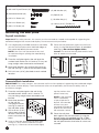
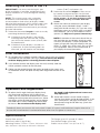
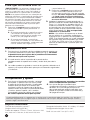
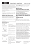
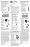
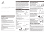
Full-Motion Wall Mount
For LCD Monitors and Displays
Installation Manual
Thank you for choosing the RCA MAF35BKR Universal
Full-Motion Wall Mount For LCD Monitors and Displays.
This mount can be used for all major brands of up to 37”
flat panel TVs, 55 lbs (25 kg) or under. Before attempting to
mount your television set, please remove all parts from this
package and read the installation instructions carefully.
WARNING: Use of this mount with a TV weighing over
55 lbs. or with a screen larger than 37" could cause
the mount to fail causing property damage and/or
personal injury.
MAF35BKR
Fits TVs up to 37”
Maximum Load
Capacity – 55 lb (25 kg)
CAUTION:
This wall mount is intended for
use only with the maximum
weight of 25 kg/55 bls. Use with
heavier than the maximum weights
indicated may result in instability
causing possible injury. Follow
the installation and operation
instructions carefully.
English
flat panel solutions
Safety precautions
Follow these precautions to ensure safe installation and mounting of your flat panel TV.
1. Read these instructions carefully before you
begin. If you are unsure of any part of the
process, contact a professional contractor or
installer for assistance. Improper installation can
result in injury or damage.
2. The wall or mounting surface must be capable
of supporting the combined weight of the mount
and the display; if not, the structure must be
reinforced.
3. Locate pipes, wires, or any other hazards in the
wall where you wish to install the mount before
drilling.
4. Safety gear and proper tools must be used.
Failure to do so can result in injury or damage.
5. Two people are recommended for installation.
Do not attempt to lift a heavy display without
assistance.
6. Follow all instructions and recommendations
regarding adequate ventilation and suitable
locations for mounting your display. Consult the
owner‘s manual for your particular display for
more information.
Keep your sales receipt to obtain warranty parts
and service and for proof of purchase. Attach it
here and record the model number. This number is
located on the product.
Model No. ___________________________________
Purchase Date: _______________________________
Dealer/Address/Phone ________________________
Preparing to install
Before beginning the installation process, verify that you have all the necessary tools on hand. The
following tools are required for proper installation:
Tools
Phillips Head Screwdriver
Electric or Portable Drill
4.8 mm (3/16”) Drill Bit and Stud Finder for
Drywall Installation
8 mm (5/16”) Masonry Bit for Concrete
Installation
Level
Para obtener
instrucciones en
español, consulte la
página 4.
Continues on next page...
1
Hardware Kit
(A) M6 x 60 Drywall Screw (x3)
(B) Concrete Anchor (x3)
(C) M4 x 12 Screw (x4)
(D) M4 x 20 Screw (x4)
(F) M6 x 20 Screw (x4)
(G) M6 Washer (x4)
(H) Spacer (x4)
(I) S8 Allen Key (x1)
(J) 4.8 mm (3/16”) Drill bit (x1)
(E) M6 x 12 Screw (x4)
Mounting the wall plate
Drywall Installation
Important! For safety reasons, this mount must be secured to a wood stud capable of supporting the
combined weight of the mount and display. Do not mount to drywall alone.
1. Use a high quality stud finder to locate a stud where
you wish to install your mount. Mark both edges of
the stud to help identify the exact center.
NOTE: You must use the center of the stud
to avoid cracking or splitting the wood during
installation.
5. Place the wall plate back against the wall and
attach it using the drywall screws (A) provided
(see Fig. 2). Do not over-tighten these
screws. Ensure that the wall plate remains level
after all screws are secured.
2. Place the wall plate against the wall over the
marked stud. Make sure it is level or TV may not
hang straight when attached to wall bracket.
3. Mark three locations for securing the mount to
the wall (see Fig. 1) and set the wall plate aside.
4. Drill a 4.8 mm (3/16”) pilot hole at each marked
location.
Fig.1
Fig.2
Concrete/Brick Installation
IMPORTANT! For safety reasons, the concrete wall must be capable of supporting the combined weight
of the mount and the display. The manufacturer takes no responsibility for failure caused by walls of
insufficient strength.
1. Place the wall plate against the wall in the
2.
3.
desired location. Make sure it is level or TV
may not hang straight when attached to wall
bracket.
Mark three locations
on the wall for
securing the mount
(see Fig. 3) and set
the wall plate aside.
Drill an 8 mm (5/16”)
hole at each marked
location. Remove any
excess dust from the
Fig.3
holes.
4. Insert a Concrete Anchor (B) into each hole
so that it is flush with the concrete surface
(see Fig. 4). A hammer can be used to lightly
2
tap the anchors into
place if necessary.
NOTE: If the concrete
wall is covered by
a layer of plaster or
drywall, the concrete
anchor must pass
completely through the
layer to rest flush with
the concrete surface.
Fig.4
5. Place the wall plate
back against the wall and attach it using the
drywall screws (A) provided (see Fig. 2). Do
not over-tighten these screws. Ensure that
the wall plate remains level after all screws are
secured.
Attaching the Arms to the TV
IMPORTANT! Use extra care during this part
of the installation. If possible, avoid placing your
display facedown as it may damage the viewing
surface.
2. Determine the correct length of screw to use
NOTE: This mount comes with a selection
of different screw diameters and lengths to
accommodate a wide variety of display models.
Not all of the hardware in the kit will be used. If you
cannot find the appropriate screw size in the kit
provided, consult the manufacturer of your display
for more information.
3. Attach the mount to the back of your display
1. Determine the correct length of screw to use by
examining the back of your display:
A. If the back of your display is flat and the
mounting holes are flush with the surface,
you will use the shorter screws (C or E) from
the hardware kit.
B. If the back of your display is curved, has
a protrusion, or if the mounting holes are
recessed, you will need to use the longer
screws (D or F) and spacers (H).
English
by carefully trying one of each size (M4 and
M6) from the hardware kit. Do not force any
of the screws – if you feel resistance stop
immediately and try a smaller diameter
screw.
using the screws identied in Steps 1 and 2
along with the M6 washers (G). If you are using
the longer screws on a display with a curved or
recessed back, you may also need to use the
spacers (H). Only use a spacer if necessary.
NOTE: If the holes of the mount do not line up
with the holes on your display, check to make
sure that your display is VESA compatible. This
mount can only be used with displays that are
VESA 75, VESA 100, VESA 100 x 200, or VESA
200 compatible. Consult the manufacturer of
your display for more information.
Final Installation
1. To complete the installation,carefully slide the mount with your display
attached into the wall plate (see Fig. 5). Do not release the display
until the display plate is securely placed in the wall plate.
2. If you need to remove the display from the wall, carefully slide the
mount upwards and out of the wall plate.
3. Cables can be routed through the hooks located on the mount and
at the bottom of the wall plate to keep them organized and out of the
way.
Fig. 5
Operation and Adjustment
1. To adjust the tilt angle, hold your display firmly
with one hand and loosen the tilt adjustment
knob. You may also have to loosen the 3 screws
holding the mount plate to the mount arm. Move
the display to the desired position and re-tighten
the knob and 3 screws holding the mount plate
to the arm. Do not release the display until
the knob is fully tightened and screws are
fully tightened.
2. Swivel adjustments can be made simply by
moving your display to the desired position. If the
main swivel joint is too tight or too loose, it can
be adjusted using the S8 Allen key (I) from the
hardware kit.
Periodically clean your mount with a dry cloth. Inspect all screws and hardware at regular intervals to
ensure that no connections have become loose over time. Re-tighten as necessary.
Specifications
Display Size: up to 37”
Maximum Load: 25 kg (55 lbs)
Mounting Pattern: 75 mm x 75 mm, 100 mm x 100
mm, 200 mm x 100 mm, or 200 mm x 200 mm
Tilt Range: up to 15° up and 15° down
Pan/Swivel Range: up to 180°
Profile: 9.0 cm to 34.7 cm (3.5” to 13.7”)
3
MAF35BKR
Para TVs de hasta 37”
Capacidad de carga máxima
– 55 lb (25 kg)
Soluciones para pantallas planas
Soporte en la Pared Movimiento Total
Para Monitores y Pantallas LCD
Manual de Instalación
Gracias por elegir el Soporte para Pared de Movimiento
Total Universal RCA MAF35BKR para Monitores y Pantallas
LCD. Este soporte puede ser usado para todas las marcas
principales de TVs de Pantalla Plana de hasta 37”, 55 lbs
(25 kg) o inferiores. Antes de intentar montar su equipo de
televisión, por favor retire todas las partes de este paquete y
lea cuidadosamente las instrucciones de instalación.
ADVERTENCIA: Usar este soporte con una TV
cuyo peso exceda 55 libras o con una pantalla más
grande de 37” podría causar que el soporte cayera
ocasionando daño a la propiedad y/o lesiones
personales.
PRECAUCIÓN:
Este soporte para pared está
diseñado para usarse solamente
con el peso máximo de 25
kilos/55 libras. Utilizarlo con pesos
mayores que el máximo indicado
puede resultar en inestabilidad
causando posibles lesiones. Siga
cuidadosamente las instrucciones
de instalación y operación.
Precauciones de seguridad
Siga estas precauciones para contar con una instalación y montajes seguros de su TV de pantalla plana.
1. Lea cuidadosamente las instrucciones antes de
comenzar. Si usted no está seguro de alguna
parte del proceso, contacte a un contratista
o instalador profesional para ayuda. Una
instalación inadecuada puede resultar en un
daño o lesión profesional.
2. La superficie de montaje o la pared debe tener
la capacidad de soportar el peso combinado del
soporte y de la pantalla; si no, la estructura debe
ser reforzada.
3. Antes de perforar ubique tubos, cables o
cualquier otro obstáculo en la pared donde
usted quiere instalar el soporte.
4. Se deben utilizar equipo de seguridad y las
herramientas adecuadas. La falla en hacer esto
puede resultar en un daño o lesión.
5. Se recomiendan dos personas para hacer la
instalación. No intente levantar una pantalla
pesada sin ayuda.
6. Siga todas las instrucciones y recomendaciones
con respecto a la ventilación apropiada y a
las ubicaciones adecuadas para montar su
pantalla. Consulte el manual del propietario para
su pantalla en particular a fin de obtener más
información.
Conserve su recibo de ventas para obtener parte
y servicio en garantías y como prueba de compra.
Anéxelo aquí y registre el número de modelo. Este
número de modelo está ubicado en el producto.
Modelo No. __________________________________
Fecha de compra: ____________________________
Distribuidor/Dirección/Teléfono ________________
Preparación para instalar
Antes de comenzar el proceso de instalación, verifique que tenga todas las herramientas necesarias a
mano. Las herramientas siguientes se requieren para una instalación adecuada:
Herramientas
Desarmador con cabeza Phillips
Taladro portátil o eléctrico
Broca para taladro de 4.8 mm (3/16”) y Detector
de Clavos para instalación muro de yeso
Broca para ladrillo de 8 mm (5/16”) para
instalación de concreto
Nivel
4
For English
instructions, see
page 1.
Sino en la página siguiente...
Juego de herrajes
(F) Tornillo M6 x 20 (x4)
(A) Tornillo para panel de
yeso M6 x 60 (x3)
(G) Arandela M6 (x4)
(H) Espaciador (x4)
(B) Ancla para concreto (x3)
(I) Llave Allen S8 (x1)
(C) Tornillo M4 x 12 (x4)
(J) Broca para taladro 4.8 mm (3/16”) (x1
(D) Tornillo M4 x 20 (x4)
(E) Tornillo M6 x 12 (x4)
Montaje de la placa de la pared
¡Importante! Por razones de seguridad, este soporte debe ser asegurado a un perno de madera con
capacidad para soportar el peso combinado del soporte y de la pantalla. No monte solamente al panel de
yeso.
1. Use un detector de clavos de alta calidad para
ubicar un perno donde usted quiere instalar un
soporte. Marque dos ubicaciones en las orillas del
perno para ayudar a identificar el centro exacto.
NOTA: Usted debe usar el centro del perno para
evitar ruptura o división de la madera durante la
instalación.
5. Coloque la parte posterior de la placa de
la pared contra la pared y fíjela usando los
tornillos para panel de yeso (A) suministrados
(ver Fig. 2). No apriete en forma excesiva estos
tornillos. Asegúrese de que la placa de la pared
permanece nivelada después de que todos los
tornillos estén fijados en forma segura.
2. Coloque la placa de la pared contra la pared
sobre el perno marcado. Asegúrese de que esté
nivelado o la TV puede no colgar en forma recta
cuando sea colocada en el soporte de la pared.
3. Marque tres ubicaciones para asegurar el
soporte a la pared (ver Fig. 1) y coloque la placa
de pared a un lado.
4. Perfore un orificio piloto de 4.8 mm (3/16”) en
cada ubicación marcada.
Fig.1
Fig.2
Instalación Concreto/Tabique
¡IMPORTANTE! Por razones de seguridad, la pared de concreto debe tener la capacidad de soportar el
peso combinado del soporte y la pantalla. El fabricante no asume responsabilidad por fallas causadas por
paredes de fortaleza insuficiente.
para colocar las anclas
1. Coloque la placa de la pared contra la pared
en su lugar si es
en la ubicación deseada. Asegúrese que
necesario.
esté nivelada o la TV puede no colgar recta
cuando esté colocada en el soporte de la
NOTA: si la pared de
pared.
concreto está cubierta
por una capa de yeso
2. Marque tres
o panel de yeso, el
ubicaciones en la
ancla de concreto debe
pared para asegurar
pasar completamente a
el soporte (ver Fig. 3)
través de la capa para
y coloque a un lado la
permanecer a nivel
placa de la pared.
Fig.4
con la superficie de
3. Perfore un orificio de
concreto.
8 mm (5/16”) en cada
5. Coloque de regreso a la placa de la pared
ubicación marcada.
contra la pared y fíjela usando los tornillos
Retire el exceso de
Fig.3
para panel de yeso (A) suministrados (ver Fig.
polvo de los orificios.
2). No apriete en exceso estos tornillos.
4. Inserte un ancla de concreto (B) en cada
Asegure que la placa de la pared permanezca
orificio de manera que esté al ras con la
a nivel después de que todos los tornillos estén
superficie de concreto (ver Fig. 4). Se puede
colocados en forma segura.
usar un martillo para ligeramente golpear
5
Español
Instalación en panel de yeso
Para fijar los brazos a la TV
¡IMPORTANTE! Use extremo cuidado durante
esta parte de la instalación. Si es posible, evite
colocar su televisión con la cara hacia abajo ya
que puede dañar la superficie de visualización.
NOTA: este soporte viene con una selección de
diferentes diámetros y longitudes de tornillos para
acomodarse a una amplia variedad de modelos
de pantalla. No todos los herrajes efectuados se
usarán. Si usted no puede encontrar el tamaño
del tornillo apropiado en el juego suministrado,
consulte con el fabricante de su pantalla para
obtener más información.
1. Determine la longitud correcta del tornillo a
utilizar examinando la parte posterior de su
pantalla:
A. Si la parte posterior de su pantalla es plana
y los orificios de soporte están a ras con
la superficie, usted usará los tornillos más
cortos (C o E) del juego de herrajes.
B. Si la parte posterior de su pantalla es
curva, tiene una saliente, o si los orificios de
soporte están empotrados, usted necesitará
usar los tornillos más largos (D o F)
y espaciadores (H).
2. Determine la longitud correcta del tornillo
3.
a utilizar intentando cuidadosamente con
uno de cada tamaño (M4 y M6) del juego de
herrajes. No force ninguno de los tornillos
- si usted siente resistencia deténgase
inmediatamente e intente con un tornillo
de menor diámetro.
Coloque el soporte en la parte posterior de su
pantalla usando los tornillos identificados en los
Pasos 1 y 2 junto con las arandelas M6 (G). Si
usted está usando los tornillos más largos con
una pantalla con una parte posterior curva o
hueca, puede ser que usted también necesite
utilizar espaciadores (H). Use un espaciador
solamente si es necesario.
NOTA: si los orificios de soporte no se alinean
con los orificios en su pantalla, verifique para
asegurarse que su pantalla sea compatible con
VESA. Este soporte puede ser usado solamente
con pantallas que sean compatibles con VESA
75, VESA 100, VESA 100 x 200, o VESA 200.
Consulte al fabricante de su pantalla para más
información.
Instalación Final
1. Para terminar la instalación, deslice cuidadosamente el soporte con
su pantalla colocada en la placa de la pared (ver Fig. 5). No suelte
la pantalla hasta que la placa de la pantalla esté firmemente
colocada en la placa de la pared.
2. Si usted necesita retirar la pantalla de la pared, deslice
cuidadosamente el soporte hacia arriba y afuera de la placa de la
pared.
3. Los cables pueden ser guiados a través de los ganchos ubicados en el
soporte y en la parte inferior de la placa para mantenerlos organizados
y sin obstruir.
Fig. 5
Cooperación y ajuste
1. Para ajustar el ángulo de inclinación, sostenga
firmemente su pantalla con una mano y afloje
la perilla de ajuste de inclinación. Usted puede
también tener que aflojar los 3 tornillos que
sostienen la placa de soporte con el brazo de
soporte. Mueva la pantalla a la posición deseada
y vuelva a apretar la perilla y los 3 tornillos
sosteniendo la placa de soporte con el brazo.
No suelte la pantalla hasta que la perilla
2.
esté completamente apretada y los tornillos
estén completamente apretados.
Los ajustes de giro se pueden hacer
simplemente moviendo su pantalla a la posición
deseada. Si la junta de giro principal está
demasiado apretada o demasiado floja, ésta
puede ser ajustada usando la llave Allen S8 (I)
del juego de herrajes.
Limpie periódicamente su soporte con un paño seco. Inspeccione todos los tornillos y los herrajes a
intervalos regulares para asegurar que las conexiones no se hayan aflojado con el tiempo. Vuelva a
apretar según sea necesario.
Especificaciones
Tamaño de la pantalla: hasta 37”
Carga máxima: 25 kg (55 lbs)
Patrón de soporte: 75 mm x 75 mm, 100 mm x 100
mm, 200 mm x 100 mm, ó 200 mm x 200 mm
6
Rango de inclinación: hasta 15° arriba y 15° abajo
Rango panorámico/giro: hasta 180°
Perfil: 9.0 cm a 34.7 cm (3.5” a 13.7”)
Limited Lifetime Warranty
VOXX Accessories Corporation (the “Company”) warrants to you the original retail purchaser of this product
that should it, under normal use and conditions, be proven defective in material or workmanship during
its lifetime while you own it, such defect(s) will be repaired or replaced (at the Company’s option) without
charge for parts and repair labor. To obtain repair or replacement within the terms of this Warranty, the
product is to be delivered with proof of warranty coverage (e.g. dated bill of sale), specification of defect(s),
transportation prepaid, to the Company at the address shown below. Do not return this product to the
Retailer.
This Warranty does not cover product purchased, serviced or used outside the United States or Canada. This
Warranty is not transferable and does not extend to costs incurred for installation, removal or reinstallation
of the product. This Warranty does not apply if in the Company’s opinion, the product has been damaged
through alteration, improper installation, mishandling, misuse, neglect, or accident. THE EXTENT OF THE
COMPANY’S LIABILITY UNDER THIS WARRANTY IS LIMITED TO THE REPAIR OR REPLACEMENT
PROVIDED ABOVE AND, IN NO EVENT, SHALL THE COMPANY’S LIABILITY EXCEED THE PURCHASE
PRICE PAID BY PURCHASER FOR THE PRODUCT.
This Warranty is in lieu of all other express warranties or liabilities. ANY IMPLIED WARRANTIES,
INCLUDING ANY IMPLIED WARRANTY OF MERCHANTABILITY OR FITNESS FOR A PARTICULAR
PURPOSE SHALL BE LIMITED TO DURATION OF THIS WARRANTY. IN NO CASE SHALL THE
COMPANY BE LIABLE FOR ANY CONSEQUENTIAL OR INCIDENTAL DAMAGES WHATSOEVER. No
person or representative is authorized to assume for the Company any liability other than expressed herein
in connection with the sale of this product.
Some states/provinces do not allow limitations on how long an implied warranty lasts or the exclusion or
limitation of incidental or consequential damage so the above limitations or exclusions may not apply to
you. This Warranty gives you specific legal rights and you may also have other rights which vary from state/
province to state/province.
U.S.A.: Audiovox Return Center, 150 Marcus Blvd., Hauppauge, New York 11788
CANADA: Audiovox Return Center, c/o Genco, 6685 Kennedy Road, Unit 3, Door 16, Mississauga, Ontario
L5T 3A5
Garantía Limitada Durante la Vida Útil del Producto
VOXX Accessories Corporation (la “Compañía”) le garantiza a usted, el comprador original de este producto
que si, bajo condiciones y uso normales, se encontrara que presenta defectos materiales o de mano de obra
durante su vida útil mientras sea de su propiedad, tales defectos serán reparados o reemplazados (a opción de
la Compañía) sin cargo alguno por las piezas y labores de reparación. Para obtener los servicios de reparación
o reemplazo dentro de los términos de esta Garantía, el producto se entregará con prueba de cubierta de
garantía (por ejemplo, factura fechada de venta), especificación de los defectos, transporte prepagado, a la
Compañía a la dirección indicada abajo. No devuelva este producto al Distribuidor.
Esta Garantía no cubre un producto adquirido, mantenido o utilizado fuera de los Estados Unidos o Canadá.
Esta Garantía no es transferible y no incluye los costos incurridos en la instalación, remoción o reinstalación
de este producto. Esta Garantía no aplica si, es opinión de la Compañía que, este producto ha sufrido daños
debido a alteraciones, instalación inadecuada, abuso, uso indebido, negligencia o accidente. EL ALCANCE DE
LA RESPONSABILIDAD DE LA COMPAÑÍA BAJO ESTA GARANTÍA ESTÁ LIMITADO A LA REPARACIÓN
O EL REEMPLAZO PROVISTO ARRIBA Y, EN NINGÚN CASO, DEBERÁ LA RESPONSABILIDAD DE LA
COMPAÑÍA EXCEDER EL PRECIO DE COMPRA PAGADO POR EL COMPRADOR DE ESTE PRODUCTO.
Esta Garantía reemplaza cualesquiera otras responsabilidades o garantías expresas. CUALESQUIERA
GARANTÍAS IMPLÍCITAS, INCLUYENDO CUALQUIER GARANTÍA IMPLÍCITA DE COMERCIABILIDAD
O ADAPTABILIDAD PARA UN PROPÓSITO EN PARTICULAR ESTARÁN LIMITADAS A LA DURACIÓN
DE ESTA GARANTÍA. EN NINGÚN CASO LA COMPAÑÍA SERÁ RESPONSABLE POR DAÑOS
EMERGENTES O INCIDENTALES. Ninguna persona ni representante está autorizado a asumir, a nombre de
la Compañía, ninguna responsabilidad salvo la expresada aquí en conexión con la venta de este producto.
Algunos estados/provincias no permiten limitaciones sobre la duración de una garantía implícita o la
exclusión o la limitación de daños incidentales o emergentes, de modo que es posible que las limitaciones o
exclusiones anteriores no apliquen en su caso. Esta Garantía le confiere derechos legales específicos; según el
estado/provincia, puede disfrutar además de otros derechos.
EE.UU.: Audiovox Return Center, 150 Marcus Blvd., Hauppauge, New York 11788
CANADÁ:: Audiovox Return Center, c/o Genco, 6685 Kennedy Road, Unit 3, Door 16, Mississauga, Ontario
L5T 3A5
7
©2012 VOXX Accessories Corporation
Trademark(s) Registered, Marcas Registradas.
All other brands and product names are trademarks or registered trademarks of their respective owners.
/ Todas las demás marcas y nombres de productos son marcas comerciales o marcas comerciales
registradas de sus respectivos dueños.
www.rcaaudiovideo.com
MAF35BKR_AR_IB_00