1
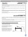
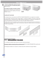
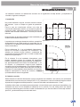
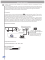
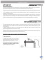
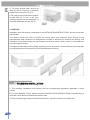
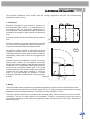
LAGUNA
NEXUS
MITTA
Español
Manual de Instalación
Bañeras de hidromasaje
English
Installation manual
Hydromassage bathtubs
Manual del Instalación
2
Installation manual
INDICE - CONTENTS
ESPAÑOL
Manual de instalación
3
ENGLISH
Installation manual
7
Manual de Instalación
Español
INTRODUCCIÓN
Las bañeras de Hidromasaje Gala han sido fabricadas con una especial atención a la calidad de los
materiales. Igualmente, cada bañera de hidromasaje antes de llegar a su destino ha superado rigurosos
controles técnicos y de seguridad.
Para el correcto funcionamiento de la bañera de hidromasaje, rogamos se sigan las siguientes
instrucciones:
1. La instalación debe ser realizada por personal cualificado y de acuerdo con la normativa vigente en
cada país.
2. La bañera debe conservar sus protecciones hasta el final de la obra, con objeto de prevenir posibles
desperfectos. Para mover la bañera, cogerla por el armazón, nunca debe ser transportada arrastrándola
o sujetándola por las tuberías.
3. Antes de proceder a su instalación, comprobar que la bañera no ha sufrido daño alguno durante
el transporte o manipulación.
INSTALACIÓN DE LA BAÑERA
La instalación de la bañera de hidromasaje se realizará de acuerdo con las INSTRUCCIONES DE
MONTAJE de cada modelo, que se adjunta con la bañera, presentando especial atención a los
siguientes puntos:
1. Antes de proceder a su instalación, llenar la bañera y comprobar que no existen fugas y que todos
los elementos del hidromasaje funcionan correctamente.
2. Cuando se proceda a siliconar la bañera respetar las cotas indicadas, con el fin de evitar las pequeñas
vibraciones que pueda ocasionar el motor de la bañera en su normal funcionamiento.
EL CIERRE DE LA BAÑERA PUEDE REALIZARSE DE DOS FORMAS:
1- MEDIANTE MURETES DE OBRA
2. Habrá que tener en cuenta que la zona
del motor debe quedar cerrada, pero con la
posibilidad de acceder al mismo para una
eventual reparación. Además será
necesario prever una rejilla para la
ventilación del equipo de hidromasaje.
3 mm
1. Se tendrá la precaución de dejar una
holgura entre la bañera y el murete de 3
mm., para así poder sellar la junta con un
cordón de silicona (Fig.1).
Fig-1
243
Manual de Instalación
4
3. Colocar tapa de registro situada en la zona
del motor, de 70x45 cm. minimo, de manera
que sea necesario una herramienta para su
apertura.(Fig. 2).
4. Colocar una rejilla en la tapa de registro,
con superficie mínima de 200 cm2. Ésta
tendrá unas aberturas que impidan la
penetración de una varilla de 8 mm de
diámetro (Fig. 2).
2- MEDIANTE FALDONES
El montaje de éstos se describe en las INSTRUCCIONES DE MONTAJE, que se adjunta con la bañera.
Con este sistema evitaremos colocar la tapa registro y la rejilla de ventilación. El acceso al equipo de
hidromasaje para su mantenimiento se realiza retirando los faldones y la ventilación se efectúa por la
ranura que queda entre el suelo y el faldón. En ningún caso debe sellarse esta ranura.
El faldón siempre irá bien anclado de manera que sea necesaria una herramienta para su extracción, la
manipulación de éste únicamente debe ser realizada por personal cualificado (Servicio de Asistencia
Técnica correspondiente).
INSTALACIÓN DE FONTANERÍA
1. La instalación hidráulica debe cumplir la normativa vigente de cada país.
2. Para la instalación de la grifería debe consultarse las INSTRUCCIONES DE MONTAJE específicas de
cada bañera, donde se aconseja la ubicación de la misma.
3. El desagüe automático se conectará a la red de evacuación mediante un manguito elástico.
3
Manual de Instalación
245
INSTALACIÓN ELÉCTRICA
La instalación eléctrica se realizará de acuerdo con el reglamento de baja tensión y cumpliendo la
normativa vigente en cada país.
1. Instalación
en
3
en
2
Vol
um
Volumen 0
Vol
um
Las partes que contengan elementos activos, excepto los
alimentados con muy baja tensión de seguridad que no
exceda de 12 V, deben ser inaccesibles para una persona
dentro de la bañera.
Vo
lu
Ninguna parte de la bañera debe de estar localizada por
encima de la misma durante su uso.
m
en
1
No podrá realizarse ninguna conexión eléctrica dentro
del volumen 1 que no cumpla un grado de protección
IPx5.
Para lo que se recomienda utilizar una caja de
conexiones ideada para este fin, que cumpla el grado de
protección citado. Igualmente, se tendrá la precaución de
realizar esta conexión situándola a 20 mm por encima
del suelo.
Fig-3
n3
me
Volumen 1
Vo
lu
En el volumen 2 no se instalarán interruptores, pero
podrán instalarse tomas de corriente de seguridad.
Podrán instalarse aparatos de alumbrado de instalación
fija, preferentemente de la Clase II de aislamiento, o, en
su defecto, no presentarán ninguna parte metálica
accesible y en los portalámparas no se podrán establecer
contactos fortuitos con partes activas al poner o quitar las
lámparas. En estos aparatos de alumbrado no se podrán
disponer interruptores ni tomas de corriente, aVolumen
menos 0
que estas últimas sean de seguridad.
Volu
men
2
En los volúmenes 0 y 1 no se instalarán interruptores,
tomas de corriente ni aparatos de iluminación. Se
admiten por encima de este volumen, contactores de
mando de sonería accionados por un cordón o cadena de
material no higroscópico.
2. Cable de conexión
Debe utilizarse el cable de alimentación que se suministra con la bañera u otro similar (con cubierta de
características no menores que el de tipo H05 V V-F), teniendo en cuenta la caída de tensión máxima
impuesta en el reglamento de baja tensión. La sección del cable suministrado es de 1,5 mm2.
La bañera debe estar conectada permanentemente a la red eléctrica sin conexiones intermedias y a la
instalación de tierra. No es aceptable la utilización de un enchufe. Por ello, debe existir una caja de
conexiones eléctricas para conectar el cable de alimentación que lleva la bañera. Dicha caja será del
tipo IPx5, y se situará 20cm por encima del suelo.
Manual de Instalación
6
Cualquier intervención será realizada por el personal del Servicio de Asistencia Técnica
correspondiente.
En caso de reemplazar este cable, recuerde que el hilo amarillo/verde de toma de tierra debe tener al
menos una longitud 40 mm superior que los hilos de fase y neutro. De esta manera se asegurará que, en
el caso que se produjese un estirón, el último cable en desconectarse de la regleta sería el de tierra,
no perdiéndose así la protección eléctrica en ningún momento.
3. Protección
La bañera dispone de una conexión equipotencial
entre sus elementos metálicos. Esta conexión,
situada en la placa de fijación del motor, deberá conectarse a la instalación equipotencial del cuarto de
baño. Este cable de conexión podrá tener una sección de 2,5 mm2 hasta 6 mm2.
La instalación eléctrica de la vivienda debe disponer de un interruptor diferencial (*) de 30 mA como
mínimo, según la normativa vigente en la zona geográfica donde se instala y un magnetotérmico
adecuado al consumo de cada modelo de bañera (ver consumos en la lista de especificaciones
técnicas), que disponga de desconexión omnipolar y con una distancia de apertura mínima de 3 mm.
Ambos interruptores deben estar fuera de los volúmenes de protección del cuarto de baño.
4. Esquema de conexiones
Según colores de la placa.
Caja electrónica de control.
NL
Detector
de
nivel
LN
Interruptor
(*) Interruptor
magnetotérmico diferencial 30mA
NO INCLUIDOS EN EL SUMINISTRO
Colocados fuera del volumen de
protección de la bañera (Fig. 3)
Pulsador marcha-paro
Electrobomba
5. Especificaciones técnicas
• Tensión de alimentación: . .220... 230V~; 50Hz
ELECTROBOMBA AGUA
Potencia nominal
Intensidad nominal
Protección
650W
2,9A
IP55
Installation manual
English
INTRODUCTION
Gala hydromassage baths are manufactured using top quality materials. Before reaching its destination,
each hydromassage bath has been subjected to strict technical and safety controls.
In order to ensure the correct operation of your hydromassage bath, please follow the instructions below:
1. The installation must be carried out by qualified personnel and in accordance with the current
regulations of each country.
2. The bath’s protective elements must remain in place until the installation work has been completed in
order to prevent the risk of damage. The bath must be lifted by its frame, not dragged or lifted by its pipes.
3. Before installing the bath, check that no damage has occured during transportation or handling.
BATHTUB INSTALLATION
The hydromassage bath must be installed in accordance with the INSTALLATION INSTRUCTIONS
corresponding to each model, which are enclosed with the bathtub, paying special attention to the
following points:
1. Before installing the bath, fill it with water and check that there are no leaks and that all the
hydromassage bath elements operate correctly.
2. When applying silicone respect the indicated measures in order to avoid the small vibrations that can
cause the motor of the bathtub during the normal functioning .
THE BATHTUB MAY BE FRONTED IN TWO DIFFERENT WAYS:
1- MASONRY WALL
1. Take care to leave a 2-3 mm. space
between the bath and the wall in order to be
able to seal the joint with silicone (Fig. 1).
3 mm
2. The motor area must be enclosed, but
accessible for possible repairs. A grille
must also be provided for ventilation of the
hydromassage bath equipment.
Fig-1
247
Installation manual
8
3. The motor access hatch must be at
least 70 x 45 cm. minimum, so that tools
will be required to open it (Fig. 2).
4.The grille on the access hatch must be
at least 200 cm2 in size. It will have
openings that prevent the penetration of
a rod with a diameter of 8 mm (Fig. 2).
2- SKIRTING
Installation with with skirting is described in the INSTALLATION INSTRUCTIONS, which are enclosed
with the bath.
This system avoids the need to provide an access hatch and ventilation grille. Access to the
hydromassage bath equipment for maintenance purposes is achieved by removing the skirting, and
ventilation is provided through the gap between the skirting and the floor. Under no circumstances
should this gap be sealed
The bath skirt will always be firmly fitted, requiring a tool for its removal. This tool should only be handled
by qualified personnel (corresponding Technical Assistance Service).
PLUMBING INSTALLATION
1. The plumbing installation must comply with the corresponding regulations applicable in each
country.
2. For the installation of taps, please consult the INSTALLATION INSTRUCTIONS corresponding to
each bath, which advise on how best to position them.
3 .The automatic plug must be connected to the effusion system by means of an elastic joint.
Installation manual
249
ELECTRICAL INSTALLATION
The electrical installation must comply with low voltage regulations and with the corresponding
regulations of each country.
1. Installation
e3
e2
Vol
um
Volume 0
Vol
um
Sections containing live parts, except those powered
by a very low safe voltage that does not exceed 12 V,
must be inaccessible to a person inside the bath.
Vo
lu
No part of the bath should be situated above it while in
use.
m
e
1
Electrical connections must provide a minimum of
Ipx5 protection within volume 1. A connecting box (in
accordance with the protection established) is
recommended. Care must also be taken to make this
connection at a height of more than 20 mm above the
floor.
Fig-3
3
me
Volume 1
Vo
lu
Switches shall not be installed in volume 2, however
safety power sockets can be installed. Fixed light
fittings may also be installed, preferably with category
II insulation or, if unavailable, install those which do
not have any accessible metallic part. In the lamp
holders it shall not be possible to make any accidental
contact with live parts when inserting or removing
bulbs. In such light fittings no switches or power
sockets are allowed, except if these are safety power
sockets.
Volume 0
Volu
me
2
No switches, power sockets or light fittings shall be
installed in volumes 0 and 1. Above these volumes it
shall be permissible to have sound control contactors
operated by a draw-cord or chain of non-hygroscopic
material.
2. Wiring
The power cable used must be the one supplied with the bath or another of similar characteristics (with
the cover having characteristics not inferior to type H05 V V-F), taking into account the maximum voltage
stipulated in the low voltage regulations. The section of cable supplied is 1,5 mm2.
The bath must be permanently connected to the electrical mains, with no extensions, and to the earth
installation. The use of a plug socket is not acceptable. Therefore, an electrical junction box must be
provided for connecting to the cable that supplies the bath. Said box will be of IPx5 type, fitted 20 cm
above the ground.
Installation manual
10
All interventions must be carried out by the personnel of the corresponding Technical Assistance Service.
If this cable is replaced, remember that the yellow-green earth wire must be at least 40 mm longer than
the live and neutral wires. This will ensure that if the cable is jerked, the last wire to disconnect will be the
earth wire, thus maintaining electrical protection at all times.
3. Protection
The bath is provided with equipotential connection
between its metallic elements. This connection,
located on the motor base plate, must be connected to the bathroom’s equipotential installation. The
connecting wire may have a section from anywhere between 2,5 mm2 and 6 mm2.
The electrical wiring of the house must include a differential circuit breaker of at least 30 mA, according to
the current regulations of the geographical area where it is installed, and a thermomagnetic circuit
breaker suited to the power consumption of each bath model. (see consumption on the technical
specifications). The latter will be provided with an omnipolar disconnection and with an opening distance
of at least 3 mm. Both circuit breakers must be located outside the protection volumes of the bathroom.
4. Wiring diagrams
According to plaque colors.
Electronic control box
NL
LN
Level
detector
Magnetothermal Differential
circuit breaker circuit breaker
NOT INCLUDED IN THIS SUPPLY
Located outside the bath
protection volumnes (Fig. 3)
On-Off button
Water hydromassage pump
5. Technical specifications:
• Supply voltage: . . . . . . . . . . . . . .220... 230V~; 50Hz
WATER PUMP
Wattage rating
Rated current
Protection
650W
2,9A
IP55
NOTAS, NOTES
15
24
CERÁMICAS GALA, S.A.
+34-947 47 41 00
+34-947 47 41 03
e-mail: [email protected]
24417 - 06/08/10
Ctra. Madrid - Irún, Km. 244
Apartado de Correos, 293
09080 BURGOS - ESPAÑA
www.gala.es
Las medidas e información son a título orientativo y susceptibles de modificación sin previo aviso. Este documento anula los anteriores.
All information and dimensions should be considered merely approximate and are subject to modification without notice. This document cancels the former ones.


![Hoja de Instrucciones 252-516S [Spanish, 2 MB, 8/29/2005]](http://vs1.manualzilla.com/store/data/006168040_1-eb463dbe27bb81ca9edf8351d8462e04-150x150.png)