1
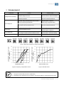
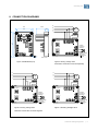
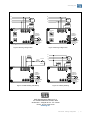
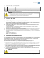
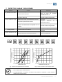
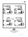
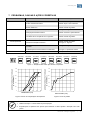
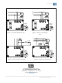
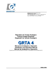
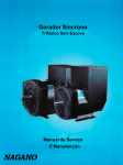
Automatic Voltage Regulator Regulador Automático de Tensión Regulador de tensão automático EA05A-WG Installation and Operation Manual (page 2-6) Manual de instalació n y operació n (page 7-11) Manual de instalação e operação (page 12-16) www.weg.net 1. INTRODUCTION When a three-phase generator is supplying a load, the N phase current will vary with the load shared by each of the 3 phases (load imbalance). Hence, the voltage from N phase to each of the 3 phases – R,S,T - will also change. So when the rated voltage of a traditional single input AVR is above 220V using the N phase as a detection source will increase voltage fluctuations and easily leads to voltage imbalance. The EA05A-WG improves the above situation; increasing the usable range of generator rated voltages that can serve as the “Phase” voltage for detection, such as 277V 380V, 440V, etc. 2. SPECIFICATION Nominal operating current Peak current (max. 10 sec.) Sensing Input Power supply Output voltage Field resistance Static regulation Voltage build-up Operating frequency Under Frequency protection (U/F) Factory setting External voltage adjustment Operating Temperature EMI suppression Maximum power consumption Approximate weight 5A 7A SW2 ON SW3 ON (220V) 180 – 250 Vac SW2 OFF SW3 ON (277V) 240 – 310 Vac SW2 ON SW3 OFF (380V) 315 – 440 Vac SW2 OFF SW3 OFF (440V) 370 – 510 Vac 1 phase 2 wire (DIP switch) 100 - 300 Vac (1 phase 2 wire) Max. 63 Vdc @ 220 Vac input Max. 90 Vdc @ 240 Vac input Min. 15 Ω Max. 100 Ω < ± 0.5% (with 4% engine governing) Residual voltage at AVR terminal > 5 Vac 50/60 Hz (DIP switch) For 60 Hz operation preset at 55Hz For 50 Hz operation preset at 45Hz 7% with 1kΩ/1W potentiometer -40 - +65°C EMI Filter Max. 8W 183g ± 2% 3. IDENTIFICATION OF CONNECTION TERMINALS E1/E2, E3/4: Sensing voltage (220/277/380/440 Vac) 3, E3/4: Power supply. EXT.VR: Connection for potentiometer 1kΩ/1W (Must use insulated stranded wire for connection) F+, F-: Connection for generator field. NOTE 1. Sensing voltage 220 Vac : terminals 3 and E1/E2 can be connected together (see Fig.6) or separately (see Fig.5). Sensing voltage 277 / 380 / 440 Vac: terminals 3, E3/4 and E1/E2, E3/4 must be connected separately (see Fig.7 , 8 and 9). The voltage between 3 and E3/4 must be less than or equal to 300 Vac. 2. If no potentiometer is used, keep EXT.VR terminal connected. (shorted) 3. Terminal Cable AWG 16 (1.25mm2) 85C , above 600 V. Automatic Voltage Regulator | 2 www.weg.net 4. TRIMPOTS FUNCTION Trimpot Function VOLT Voltage adjustment STAB Stability adjustment U/F Under frequency adjustment Adjustment Turning it clockwise to increase voltage and counterclockwise decreases Turning it clockwise , dynamic response will be slower Turning it clockwise to increase U/F and counterclockwise decreases. DIP Switch: settings for “sensing voltage” and “frequency” (see Fig.1). ATTENTION 1. Before connecting the regulator to the generator, check the installation manual and the nominal reference voltage. Incorrect connection can damage the AVR or other equipment. 2. Incorrect voltage and frequency adjustment can damage AVR. 5. AVR ADJUSTMENT Check the setting of voltage / frequency before starting the generator. Before starting the generator, turn VOLT and STAB trimpots fully counterclockwise. When the generator starts up and running at a constant speed, turn VOLT trimpot clockwise to reach the required output voltage. (If an external adjustment potentiometer is used, it needs to be adjusted to the middle position before adjusting VOLT trimpot). Turn the STAB trimpot clockwise slowly to set the response time (dynamic response) between the AVR and the generator. If setting too high, the voltage will oscillates. If setting too low, the voltage will change too much when experiencing heavy loads. An analog voltmeter recommended for "Stability Adjustment". Adjust until the pointer is stationary. This will enhance the voltage drift during heavy load. It’s not necessary to adjust the UFRO function. The under frequency protection (U/F) is factory set. EA05A-WG’s roll-off point for 60 Hz mode is preset at 55 Hz, and for 50 Hz mode is preset at 45 Hz. UFRO DIP: Close - please refer to solid curve in Figure 2. Open - please refer to dotted curve in Figure 2. 6. FIELD FLASHING Generation begins through the residual voltage of the generator. Once the voltage has reached above 5 Vac, the regulator controls the generator voltage causing it to rise through the initial ramp in approximately 3 seconds. When the generator reaches its nominal value, it will maintain constant generator output voltage according to the set value. If the residual voltage on the wires F + and F- power output of the regulator is below 5 Vac, in this case it is recommended to stop the generator and performing the following steps (see Fig.10): a. b. c. d. Disconnect the regulator field terminal and apply no more 3-12 Vdc resistor in series with a 3-5 ohms connected in such a way that the positive battery cable is going to F + and the negative cable which goes to F-. Wait for about 3 seconds and remove the voltage source. With the voltage regulator disconnected, start the generator and measure the residual voltage of the generator in the auxiliary winding, which must be greater than 5 Vac. If this is so, reconnect the regulator and alternator priming should be provided normally. If voltage is less than 5 Vac, repeat the step a and b). If residual voltage is greater than 5 Vac but still unable to build up voltage, replace the voltage regulator. ATTENTION 1. Overly field flashing may damage the AVR or the field winding. Automatic Voltage Regulator | 3 www.weg.net 7. TROUBLESHOOT SYMPTOM CAUSE Voltage does not build up Out voltage low Fuse blown Out voltage high Out voltage instable 220V/50HZ ON OFF CORRECTION Engine speed is too low. Refer to the Generator Manual. Residual voltage is too low. Refer to section 6. FIELD FLASHING. F+, F– wires are inverted. Invert F+, F–. Defective Generator. Refer to the Generator Manual. The input wiring of E1/E2,3,E3/4 are not correct. Refer to Figure 5 - Figure 9. Check the external potentiometer. Check wiring and potentiometer. Under frequency. Refer to the Generator Manual. The exciter does not match the AVR. Refer to the Generator Manual. Voltage / frequency setting is incorrect. Refer to Figure 1. DIP switch setting Excessive excitation current. Refer to the Generator Manual. Refer to Figure 5 - Figure 9. A,C terminals are not connect or wiring incorrect. Refer to Figure 5 - Figure 9. The voltage / frequency selector setting incorrect. Refer to Figure 1. DIP switch setting Stability Adjustment doesn’t adjust well. Refer to Section 5. 220V/60HZ 277V/50HZ 277V/60HZ 380V/50HZ 440V/50HZ 380V/60HZ 440V/60HZ ON ON ON ON ON ON ON ON 123 123 123 123 123 123 123 123 Figure 1 DIP switch selection for voltage and frequency 120 GENERATOR OUTPUT VOLTAGE (% OF NOMINAL) GENERATOR OUTPUT VOLTAGE (% OF NOMINAL) 120 100 80 60HZ 50HZ 60 40 20 0 10 20 30 40 50 100 80 60 40 20 60 FREQUENCY (HZ) Figure 2 Frequency Compensation Curves 0 1 2 SOFT START (V/S) Figure 3 Soft Start Curve NOTE 1. Use type 5 x 20mm S505-5A fuse for replacement. 2. Specifications and appearance are for reference only and are subject to change without prior notice. Automatic Voltage Regulator | 4 www.weg.net 8. CONNECTION DIAGRAMS 69 59 N 48.5 15.8 R G S ~ T Field 101 91 220V/50HZ ON Voltage/ Frequency Selection 123 220V/60HZ ON 123 External voltage adjustment potentiometer (1k /1W) 4.5 Unit : mm Figure 4 DIMENSION (mm) Figure 5 Sensing Voltage 220V Terminals 3 and E1/E2 connected separately N N R R G S G S ~ T ~ T Field Field 220V/50HZ 277V/50HZ ON 123 ON Voltage/ Frequency Selection 220V/60HZ 277V/60HZ ON 123 Voltage/ Frequency Selection 123 ON External voltage adjustment potentiometer (1k /1W) Figure 6 Sensing Voltage 220V 123 External voltage adjustment potentiometer (1k /1W) Figure 7 Sensing Voltage 227V Terminals 3 and E1/E2 connected together Automatic Voltage Regulator | 5 www.weg.net N N R R G S G S ~ T ~ T Field Field 440V/50HZ 380V/50HZ ON ON Voltage/ Frequency Selection 123 Voltage/ Frequency Selection 123 440V/60HZ 380V/60HZ ON ON 123 123 External voltage adjustment potentiometer (1k /1W) Figure 8 Sensing Voltage 380V External voltage adjustment potentiometer (1k /1W) Figure 9 Sensing Voltage 440V N Field R G S 3~5 Ohm SWITCH DIODE ~ T Aux.winding Battery Field Voltage/ Frequency Selection Voltage/ Frequency Selection External voltage adjustment potentiometer (1k /1W) External voltage adjustment potentiometer (1k /1W) Figure 10 Field Flashing with Battery Figure 11 Auxiliary Winding WEG Equipamentos Elétricos S.A. Av. Prefeito Waldemar Grubba, 3000 89.256-900 - Jaraguá do Sul - SC - Brasil Phone: 55 (47) 3276-7919 www.weg.net Automatic Voltage Regulator | 6 www.weg.net 1. INTRODUCCIÓ N Cuando un generador trifásico está suministrando una carga, la fase N variará con la carga compartida por cada una de las 3 fases (inestabilidad o desequilibrio de la carga). Por consiguiente, el voltaje de la fase N de cada una de las 3 fases R, S, T - también cambiará. Por tanto cuando la tensión nominal de un AVR de entrada simple tradicional está por encima de 220V usando la fase N como fuente de detección aumentarán las fluctuaciones de tensión y conduce fácilmente a tensión de desequilibrio. El EA05A-WG mejora la situación anterior; aumentando el rango de uso de generadores de tensiones nominales que pueden servir como la tensión de "Fase" para la detección, tales como 277V 380V, 440V, etc. 2. CARACTERÍSTICAS TÉ CNICAS Corriente nominal de operación Corriente de Pico (max. 10s) Regeneración Alimentación de potencia Tensión de salida Resistencia de campo Regulación estática Voltaje de construir - up Frecuencia de operación Protección de sub frecuencia (U/F) ajustado de la fábrica Ajuste externo de tension Temperatura de operación Supresión de EMI El consumo de energía máximo Peso aproximado 3. 5A 7A SW2 ON SW3 ON (220V) 180 – 250 Vca SW2 OFF SW3 ON (277V) 240 – 310 Vca SW2 ON SW3 OFF (380V) 315 – 440 Vca SW2 OFF SW3 OFF (440V) 370 – 510 Vca 1 fase 2 hilos (interruptor DIP) 100 - 300 Vca (1 fase 2 hilos) Max. 63 Vcc @ 220 Vca input Max. 90 Vcc @ 240 Vca input Min. 15 Ω Max. 100 Ω < ± 0.5% (con un 4% de gobierno del motor) Tensión residual en la terminal AVR > 5 Vca 50/60 Hz (interruptor DIP) funcionamiento a 60 Hz se hace el ajuste para 55Hz funcionamiento a 50 Hz se hace el ajuste para 45Hz 7% con 1kΩ/1W potenciómetro -40ºC to +65ºC Filtro EMI Max. 8W 183g ± 2% DESCRIPCIÓ N DE LOS TERMINALES DE CONEXIÓ N E1/E2, E3/4: Regeneración de tensión (220/277/380/440 Vca) 3, E3/4: Alimentación de potencia. EXT.VR: Conexión para potenciómetro 1kΩ/1W (Debe utilizar aislado alambre trenzado para la conexión) F+, F-: Conexión para campo del generador. NOTE 1. Regeneración de tensión 220 Vca: terminales 3 y E1/E2 puede conectados juntos (ver Fig.6) o por separado (ver Fig.5). Regeneración de tensión 277/380/440 Vca: terminales 3, E3/4 y E1/E2, E3/4 debe conectarse por separado (ver Fig.7, 8 y 9). La tensión entre 3 y E3/4 debe ser menor o igual que 300 Vca. 2. SI NO POSEYERE POTENCIÓ METRO CONECTADO, MANTENER LOS TERMINALES EXT.VR CONECTADOS (CORTOCIRCUITADOS) 3. Terminal cable AWG 16 (1.25mm2) 85 C , por encima de 600 V Automatic Voltage Regulator | 7 www.weg.net 4. FUNCIÓ N DE LOS TRIMPOTS Trimpot Función Ajuste de Tensión VOLT STAB Ajuste de Estabilidad Ajuste de Bajo frecuencia U/F Ajuste Girando en el sentido horario aumenta la tensión y en sentido contrario disminuye Girando en sentido horário, la respuesta se torna más lenta. Girando en el sentido horario aumenta la faja de U/F y antihorario diminuye. Interruptor DIP: ajustes de tensión y frecuencia (ver Fig.1) ATENCIÓ N 1. Antes de conectar el regulador al generador, verifique en el manual de instalación, la tensión nominal de referencia. Una conexión incorrecta podría dañar el AVR o otros equipos 2. Una tensión incorrecta y ajuste de frecuencia pueden dañar AVR. 5. AJUSTES DEL AVR Compruebe el ajuste de tensión / frecuencia antes de arrancar el generador. Antes de iniciar el generador, Gira VOLT y STAB trimpots completamente en sentido antihorario. Cuando se pone en marcha el generador y funcionando a una velocidad constante Gira VOLT trimpot hacia la derecha para llegar a la tensión de salida requerida. (Si se utiliza potenciométro de ajuste externo de tension, que necesita ser ajustado a la posición media antes de ajustar VOLT trimpot). Gire lentamente el STAB trimpot en sentido horario para establecer tiempo de respuesta (Respuesta dinámica) entre el AVR y el generador. Si el ajuste es demasiado alto, el voltaje será oscillates. Si el ajuste es demasiado bajo, el voltaje cambiará demasiado cuando experimente cargas pesadas. Se recomienda un voltímetro analógico para "Ajuste da Estabilidad". Ajuste hasta que el puntero esté parado. Esto mejorará la velocidad de cambio de voltaje durante la carga pesada. No es necesario ajustar la función UFRO. La protección de sub frecuencia (U/F) es configuración de fábrica. El EA05A-WG tiene el punto de roll-off preestablecido en 55 Hz en el modo de 60 Hz, y en 45 Hz en el modo de 50 Hz. UFRO DIP: Cerrada: La curva sólida en Fig .2 Abierta: Curva discontinua en Fig .2 6. ENCENDIDO DEL CAMPO (FLASH) La generación empieza a través de la tensión residual del generador. Cuando el voltaje residual está por encima de 5 Vca, el regulador controla la tensión del generador haciendo con que la tensión ascienda a través de la rampa inicial en aproximadamente 3 segundos, hasta que alcance la tensión nominal. A partir de este momento, va a mantendrá la tensión de salida del generador constante de acuerdo con el valor ajustado. Si el voltaje residual en los alambres F+ y F- de salida de potencia del regulador es inferior a 5 Vca. En este caso se recomienda detener el generador y realizar los siguientes pasos (ver Fig.10): a. b. c. d. Desconectar los bornes de campo del regulador y aplicar no más de 3-12 Vcc en serie con un resistor de 3-5 ohms conectado de tal manera que el positivo de la batería vaya al cable que va a F+ y el negativo al cable que va al F-. Espere aproximadamente 3 segundos y retire la fuente de tensión. Con el regulador de tensión desconectado inicie el generador y mida el voltaje residual del generador en el bobinado auxiliar, que debe ser mayor a 5 Vca. Si esto es así, reconecte el regulador y el cebado del alternador se debe dar en forma normal. Si el voltaje medido es menor de 5 Vca repita el procedimiento del punto a y b). Si luego de repetir el magnetizado de la maquina y obtener un voltaje residual mayor a 6 Vac el alternador no se ceba, reemplace el regulador de tension. ATENCIÓ N 1. Cebar el campo demasiado podría dañar el AVR o devanado de campo. Automatic Voltage Regulator | 8 www.weg.net DEFECTOS, CAUSAS Y SOLUCIONES Defectos Causas El generador no enciende Tensión de salida muy bajo Fusible quemado Tensión de salida muy alto Tensión de salida oscila 220V/50HZ OFF Subvelocidad del generador Consultar el manual del generador.. Tensión residual muy baja Cebar el campo del Consultar la sección 6. Bornes F+, F– invertidos. Invert F+, F– Generador defectuoso Consultar el manual del generador. Regeneración E1/E2,3,E3/4 alambrado incorrecta. Ver Fig.5-9 Comprobar el potenciómetro externo. Comprobar alambrado potenciómetro externo. subfrecuencia Consultar el manual del generador.. Tensión de realimentación incompatible con el regulador. Consultar el manual del generador.. Selección de tensión y frecuencia incorrecta Ver Fig.1 Interruptor DIP corriente excesiva de excitación. Consultar el manual del generador.. Ver Fig.5-9 A,,C alambrado incorrecta. Ver Fig.5-9 Selección de tensión y frecuencia incorrecta Ver Fig.1 Interruptor DIP Estabilidad desajustada. Consultar la sección 5. 220V/60HZ 277V/50HZ 277V/60HZ 380V/50HZ 380V/60HZ 440V/50HZ generador. de 440V/60HZ ON ON ON ON ON ON ON ON 123 123 123 123 123 123 123 123 Fig. 1 selección del interruptor DIP para tensión y frecuencia TENSION DE SALIDA DE GENERATOR (% DE NOMINAL) ON Soluciones 120 TENSION DE SALIDA DE GENERATOR (% DE NOMINAL) 7. 100 80 60HZ 50HZ 60 40 20 0 10 20 30 40 50 60 FRECUENCIA (HZ) Fig. 2 Curvas de compensación de frecuencia 120 100 80 60 40 20 0 1 2 ARRANQUE SUAVE (V/S) Fig. 3 Curva de tensión en un arranque suave NOTE 1. Use un fusible Tipo 5 x 20mm S505-5A 2. Las especificaciones y el aspecto se ofrecen como pautas de orientación y están sujetas a modificaciones sin previo aviso. Automatic Voltage Regulator | 9 el www.weg.net 8. DIAGRAMA DE CONEXIÓ N N 69 59 48.5 R 15.8 G S ~ T Campo de la excitatriz 220V/50HZ 101 91 ON Tension/ Frecuencia Selection 123 220V/60HZ ON 123 Potenciometro de ajuste externo de tension (1k /1W) 4.5 Unit : mm Fig. 4 DIMENSIONAL (mm) Fig. 5 Tensión de realimentación de 220Vca. terminales 3, E1/E2 conectados por separado N N R R G S G S ~ T ~ T Field Field 220V/50HZ 277V/50HZ ON 123 ON Voltage/ Frequency Selection 220V/60HZ Voltage/ Frequency Selection 277V/60HZ ON 123 123 ON External voltage adjustment potentiometer (1k /1W) Fig. 6 Tensión de realimentación de 220Vca 123 External voltage adjustment potentiometer (1k /1W) Fig. 7 Tensión de realimentación de 277Vca terminales 3, E1/E2 conectados juntos Automatic Voltage Regulator | 10 www.weg.net N N R R G S G S ~ T ~ T Campo de la excitatriz Field 380V/50HZ 440V/50HZ ON ON Tension/ Frecuencia Selection 123 Voltage/ Frequency Selection 123 380V/60HZ 440V/60HZ ON ON 123 Potenciometro de ajuste externo de tension (1k /1W) 123 Fig. 8 Tensión de realimentación de 380Vca External voltage adjustment potentiometer (1k /1W) Fig. 9 Tensión de realimentación de 440Vca Campo de la excitatriz N R G S 3~5 Ohm interruptor diodo bateria ~ T Bobinado Auxiliar Campo de la excitatriz Tension/ Frecuencia Selection Tension/ Frecuencia Selection Potenciometro de ajuste externo de tension (1k /1W) Fig. 10 Cebar el campo con batería Potenciometro de ajuste externo de tension (1k /1W) Fig. 11 Sistema Bobinado Auxiliar WEG Equipamentos Elétricos S.A. Av. Prefeito Waldemar Grubba, 3000 89.256-900 - Jaraguá do Sul - SC - Brasil Phone: 55 (47) 3276-7919 www.weg.net Automatic Voltage Regulator | 11 www.weg.net 1. INTRODUÇ Ã O Quando um gerador trifásico está fornecendo uma carga, a corrente no neutro irá variar com a carga compartilhada por cada uma das 3 fases (cargas desbalanceadas). Consequentemente, a tensão no neutro para cada uma das 3 fases – R, S, T – irá variar também. Então quando a tensão nominal de entrada do regulador for acima de 220V usando o neutro como uma fonte de detecção, a flutuação da tensão aumenta e facilmente tende ao desbalanceamento de tensão. O EA05A-WG melhora a situação acima, aumentando a faixa de tensão nominal do gerador que pode servir como a “fase” para detecção de tensão, como 277V, 380V, 440V, etc. 2. ESPECIFICAÇ Ã O Corrente nominal de operação Corrente de pico (máx. 10 seg.) Realimentação Tensão de alimentação Tensão de saída Resistência de campo Regulação estática Tensão de escorvamento Frequência de operação Proteção de subfrequência (U/F) Ajuste externo de tensão Temperatura de operação Supressão de EMI Consumo máximo Peso aproximado 5A 7A SW2 ON SW3 ON (220V) 180 – 250 Vca SW2 OFF SW3 ON (277V) 240 – 310 Vca SW2 ON SW3 OFF (380V) 315 – 440 Vca SW2 OFF SW3 OFF (440V) 370 – 510 Vca 1 fase 2 fios (DIP switch) 100 - 300 Vca (1 fase 2 fios) Máx. 63 Vdc @ 220 Vca de entrada Máx. 90 Vdc @ 240 Vca de entrada 15 Ω a 100 Ω < ± 0.5% (com 4% motor governando) Tensão residual nos terminais do regulador > 5 Vca 50/60 Hz (DIP switch) Para 60 Hz ajustado em 55Hz Para 50 Hz ajustado em 45Hz 7% com potenciômetro de 1kΩ/1W -40 a +65°C Filtro EMI Máx. 8W 183g ± 2% 3. IDENTIFICAÇ Ã O DOS TERMINAIS DE CONEXÃ O E1/E2, E3/4: Realimentação (220/277/380/440 Vca) 3, E3/4: Alimentação da potência. EXT.VR: Conexão para potenciômetro 1kΩ/1W (Deve-se usar cabo trançado isolado para conexão) F+, F-: Conexão para o campo do gerador.. NOTA 1. Tensão de realimentação 220 Vca : terminais 3 e E1/E2 podem ser conectados juntos (ver Fig.6) ou separadamente (ver Fig.5). Tensão de realimentação 277 / 380 / 440 Vca: terminais 3, E3/4 e E1/E2, E3/4 devem ser conectados separadamente (ver Fig.7 ,8 e 9). A tensão entre 3 e E3/4 deve ser menor ou igual a 300 Vca. 2. Se não for utilizado potenciômetro, manter os terminais EXT.VR curto circuitado. 3. Utilizar fios de bitola AWG 16 (1.25mm2) 85C, 600V ou maior. Automatic Voltage Regulator | 12 www.weg.net 4. FUNÇÃO DOS TRIMPOT’S Trimpot Função VOLT Ajuste de tensão STAB Ajuste de estabilidade U/F Ajuste de subfrequência Ajustes Girando no sentido horário para aumentar a tensão e anti-horário para diminuir. Girando no sentido horário, resposta dinâmica será mais lenta. Girando no sentido horário para aumentar U/F e anti-horário para diminuir. DIP Switch: parâmetros para “tensão de realimentação” e “frequência” (ver Fig.1). ATENÇ Ã O 1. Antes de conectar o regulador ao gerador, verificar o manual de instalação e a tensão nominal de referência. Conexões incorretas podem danificar o regulador ou outro equipamento. 2. Ajustes incorretos de tensão e frequência podem danificar o regulador. 5. AJUSTES DO REGULADOR Verifique os parâmetros de tensão e frequência antes de partir o gerador. Antes de partir o gerador, gire os trimpot’s “VOLT” e “STAB” no sentido anti-horário até o fim. Quando o gerador estiver operando em rotação nominal e constante, gire o timpot “VOLT” no sentido horário até atingir a tensão de saída necessária. (Se um potenciômetro para ajuste externo for usado, é necessário posicioná-lo no centro da faixa antes do ajuste do trimpot “VOLT”). Gire o trimpot “STAB” lentamente no sentido horário para ajustar o tempo de resposta (resposta dinâmica) entre o regulador e o gerador. Se o ajuste estiver muito alto, a tensão irá oscilar. Se o ajuste for muito baixo, a tensão irá mudar demasiadamente em cargas pesadas. É recomendado utilizar um voltímetro analógico para o ajuste de estabilidade. Ajuste até o ponto estável com o gerador em vazio. Isso suavizará a variação de tensão em cargas pesadas. Não é necessário ajustar a função U/f. A proteção de subfrequência é ajustada de fábrica. EA05A-WG para 60Hz está ajustado em 55Hz e para 50Hz ajustado em 45Hz. U/f DIP Switch: Fechado – ver curva em linha sólida na Figura 2. Aberto – ver curva em linha pontilhada na Figura 2. 6. ESCORVAMENTO A geração inicia através da tensão residual do gerador. Uma vez a tensão de 5Vca ultrapassada, o regulador controla a tensão do gerador aumentando-a através de uma rampa inicial de aproximadamente 3 segundos. Quando o gerador alcança seu valor nominal, o regulador irá manter a tensão de saída do gerador constante de acordo com o valor ajustado. Se a tensão residual nos cabos F+ e F- de saída de potência do regulador for menor que 5Vca, é recomendado parar o gerador e realizar os seguintes passos (ver Fig. 10) a. b. c. d. Com a máquina acionante em repouso, desconecte o terminal de campo do regulador e aplique não mais do que 3-12Vcc em série com um resistor de 3-5 ohms conectado de tal forma que o cabo positivo da bateria esteja em F+ e o cabo negativo em F-. Aguarde aproximadamente 3 segundos e remova a fonte de tensão CC. Com o regulador de tensão desconectado, partir o motor primário e medir a tensão residual do gerador na bobina auxiliar, que deve ser maior que 5Vca. Se assim estiver, reconecte o regulador, o escorvamento dever ocorrer normalmente. Se a tensão for menor que 5Vca, repita os passos a) e b). Se a tensão residual for maior que 5Vca, mas ainda incapaz de escorvar, troque o regulador de tensão. ATENÇ Ã O 1. Escorvamentos excessivo podem danificar o regulador de tensão ou o bobinado de campo. Automatic Voltage Regulator | 13 www.weg.net 7. PROBLEMAS, CAUSAS E AÇ Õ ES CORRETIVAS DEFEITO CAUSA Tensão não escorva Tensão de saída baixa Fusível queimado Tensão de saída alta Tensão de saída oscilando 220V/50HZ ON OFF SOLUÇ Ã O Rotação do motor muito baixa. Verificar manual do gerador. Tensão residual muito baixa. Verificar seção 6. Escorvamento. Cabos F+, F– estão invertidos. Inverter F+, F–. Gerador defeituoso. Verificar manual do gerador. Conexões E1/E2, 3, E3/4 estão incorretas. Ver Figura 5 - Figura 9 Verifique potenciômetro externo. Verificar conexões e potenciômetro. Subfrequência. Verificar manual do gerador. A excitatriz não é compatível com o regulador. Verificar manual do gerador. Ajuste de tensão / frequência incorretos. Ver Figura 1. Ajustes DIP switch. Corrente de excitação excessiva. Verificar manual do gerador. Ver Figura 5 - Figura 9. Terminais E3/4, E1/E2 abertos ou conexões incorretas. Ver Figura 5 - Figura 9. Tensão/frequência selecionados incorretamente. Ver Figure 1. Ajustes DIP switch. Ajuste de estabilidade inadequado. Ver Seção 5. 220V/60HZ 277V/50HZ 277V/60HZ 380V/50HZ 440V/50HZ 380V/60HZ 440V/60HZ ON ON ON ON ON ON ON ON 123 123 123 123 123 123 123 123 Figura 1 – Seleção do DIP switch para tensão e frequência 120 GENERATOR OUTPUT VOLTAGE (% OF NOMINAL) GENERATOR OUTPUT VOLTAGE (% OF NOMINAL) 120 100 80 60HZ 50HZ 60 40 20 0 10 20 30 40 50 60 100 80 60 40 20 0 FREQUENCY (HZ) Figura 2 Curvas de compensação de frequência 1 2 SOFT START (V/S) Figura 3 Curva de partida suave NOTA 1. Utilizar fusível tipo 5 x 20mm S505-5A para reposição. 2. Especificações e aparência são apenas para referência e estão sujeitas a alteração sem aviso prévio. Automatic Voltage Regulator | 14 www.weg.net 8. DIAGRAMA DE CONEXÕ ES 69 59 N 48.5 15.8 R G S ~ T Field 101 91 220V/50HZ ON Voltage/ Frequency Selection 123 220V/60HZ ON 123 External voltage adjustment potentiometer (1k /1W) 4.5 Unit : mm Figura 4 – DIMENSÕ ES (mm) Figura 5 – Tensão de realimentação 220V Terminais 3 e E1/E2 conectados separadamente N N R R G S G S ~ T ~ T Field Field 220V/50HZ 277V/50HZ ON 123 ON Voltage/ Frequency Selection 220V/60HZ Voltage/ Frequency Selection 277V/60HZ ON 123 123 ON External voltage adjustment potentiometer (1k /1W) Figura 6 – Tensão de realimentação 220V 123 External voltage adjustment potentiometer (1k /1W) Figure 7 – Tensão de realimentação 227V Terminais 3 e E1/E2 conectados juntos Automatic Voltage Regulator | 15 www.weg.net N N R R G S G S ~ T ~ T Field Field 440V/50HZ 380V/50HZ ON ON Voltage/ Frequency Selection 123 Voltage/ Frequency Selection 123 440V/60HZ 380V/60HZ ON ON 123 123 External voltage adjustment potentiometer (1k /1W) Figura 8 – Tensão de realimentação 380V External voltage adjustment potentiometer (1k /1W) Figura 9 – Tensão de realimentação 440V N Field R G S 3~5 Ohm SWITCH DIODE ~ T Aux.winding Battery Field Voltage/ Frequency Selection Voltage/ Frequency Selection External voltage adjustment potentiometer (1k /1W) External voltage adjustment potentiometer (1k /1W) Figure 10 – Escorvar campo com bateria Figure 11 – Sistema com Bobina auxiliar WEG Equipamentos Elétricos S.A. Av. Prefeito Waldemar Grubba, 3000 89.256-900 - Jaraguá do Sul - SC - Brasil Phone: 55 (47) 3276-7919 www.weg.net ______________________________________________________________________________________ Automatic Voltage Regulator | 16