1
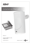
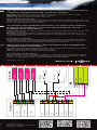
Quick Guide GB This quick guide does not replace the installation manual and the compulsory technical training course for installers. DIP switch 10 should be set to ON to let the acoustic alarm activate in case of a fault. REMEMBER to set the fog time on DIP switch 2, 3 and 4. Table for fog time is printed inside the steel cover. About avoiding accidental firing The European Norm for fog security prescribes a method to avoid accidental firing of fog - e.g. during service. However the above diagram does not include this step as the method used is different from alarm installer to alarm installer. E La presente guía rápida de instalación, en ningún caso sustituye el manual de instalación, ni el curso de capacitación técnico obligatorio para instaladores. El DIP Switch 10 debe colocarse en posición ON para dejar las señales acústicas activadas, para avisar en caso de fallo. Recuerde configurar los tiempos de disparo de la Niebla mediante los DIP Switch 2, 3 y 4. Las diferentes configuraciones de tiempos de disparo, viene descrita en la cara interior de la carcasa del Generador. Evitar disparos accidentales La Normativa europea exige una metodología para evitar disparos accidentales, en relación a la Niebla de Seguridad, por ejemplo durante el mantenimiento. Sin embargo el diagrama no incluye este paso ya que la metodología de cada instalador es diferente. DK Denne quick guide erstatter ikke manualen og det obligatoriske teknikkursus for installatører. DIP 10 bør være ON, så den indbyggede ”bibber” (akustisk signal) for fejlmelding er tilsluttet. Husk at indstille en tågetid på DIP-switchene 2, 3 og 4. Tabel for tågetid findes indvendigt i maskinens stålkabinet. Om sikring mod utilsigtet affyring Den europæiske norm for tågesikring foreskriver en metode til sikring mod utilsigtet affyring af tågen - fx under service. En sådan foranstaltning er ikke taget med i diagrammet, da metoderne er mange og individuelle fra alarminstallatør til alarminstallatør. Version 1 · DK · August 2013 Scan and get manuals/ Escanee para descargar los manuales/ Scan og hent manualer 600i/1100i/2200i QUMULUS 12 V + – Tamper – + Output + Arm – Prim + – Sec. + Disable – Fire NO NC Fluid Rly. COM. NO COM. NC Fault Rly. NO NC Fog Rly. Fog Cannon COM. PIR Motion 12 V + Tamper 12 V – Opens with alarm – Alarm Signal + 12 V – Closed in daytime – Disable Signal + Zone Tamper Zone Fluid Zone Fault Zone Fog Alarm System www.protectglobal.com FOQUS 1 Action/Acción/Handling Check/Comprobaciones/Kontrol GB:Connect the unit to 230VAC + Earth. It will take the unit 15–25 min. to warm up to operating temperature. GB:Check that the phase and zero wires are connected correctly. E: Conectar el dispositivo a 230VAC + Tierra. Dependiendo del modelo de Generador necesitará entre 15 y 25 minutos para llegar a la óptima temperatura de funcionamiento. DK:Maskinen tilsluttes 230VAC + Jord. Det tager 15–25 min. at varme op til driftstemperatur. 2 DIS GB:Connect the disable input to the 12V DC signal from the alarm system. When the alarm is disarmed, DIS must be energised. When the alarm is set (armed), the 12V DC signal must disappear. E: Se puede conectar a DIS una señal de 12V desde el sistema de alarma. Al desactivar la alarma DIS tiene que recibir estos 12V y así se desactivará el Generador. Cuando se arme la alarma y desaparezcan los 12 V de esta entrada, la unidad estará preparada para disparar. DK:Disable-indgang tilsluttes 12V DC-signal fra alarm systemet. Når alarmen er frakoblet, skal der være spænding på DIS. Når alarmen tilkobles, skal 12V DC spændingen brydes. 3 PRIM GB:The primary input must be supplied with 12V DC from the alarm system. If the alarm signal is closed in the event of burglary, DIP 6 is set to ON. If the alarm signal is opened, DIP 6 is set to OFF. E: La entrada a PRIMARIO debe recibir 12V de corriente continua desde el sistema de alarma. En caso de robo, si la señal del sistema de alarma está cerrada, el DIP Switch 6 debe estar en posición ON. Si la señal del sistema de alarma está abierta, el DIP Switch 6 ha de ponerse en posición OFF. DK:Primær indgang forsynes med 12V DC fra alarmsystemet. Hvis alarmsignalet sluttes ved indbrud, sættes DIP 6 ON – hvis alarmsignalet brydes, sættes DIP 6 OFF. 4 SEC GB:Connect the secondary input to PIR (verifying sensor). PIR is supplied with 12V DC from the Fog Cannon’s built-in 12V supply. Feed 12V – through the PIR contact assembly and connect to SEC –. Jump 12V + to SEC + on the Fog Cannon’s terminal block. The PIR contact assembly has a normal break function. Set DIP 7 to OFF. E: Conectar la entrada a SECUNDARIO desde el PIR (sensor de detección pasivo). El PIR puede ser alimentado por la salida de 12V de corriente continua del propio Generador. A falta de los 12V en el terminal SEC, el Cañón de Niebla entrará en funcionamiento. La posición del DIP Switch 7 será en OFF. DK:Sekundær indgang tilsluttes PIR (verificerende sensor). PIR forsynes med 12V DC fra tågekanonens indbyggede 12 Volt forsyning. 12V – føres igennem PIR´ens kontaktsæt og sluttes til SEC –. 12V + luses over til SEC + på tågekanonens klemrække. PIR’ens kontaktsæt har normal brydefunktion og DIP 7 sættes til OFF. 5 ARM GB:This input is normally not used. Set DIP 5 to OFF. E: Esta entrada normalmente no se utiliza. Mantenga el DIP Switch en posición OFF. DK:Denne indgang anvendes normalt ikke, og DIP 5 sættes til OFF. 6 GB:The unit is ready for testing when it is fully warmed up. Remember to set a fog time on the DIP switches 2, 3 and 4. E: La unidad estará lista para realizar el disparo cuando se haya calentado y haya alcanzado la temperatura adecuada. Recuerde configurar los tiempos de disparo con los DIP Switch 2, 3 y 4. DK:Maskinen er klar til test, når den er fuldt opvarmet. Husk, at væskedunken skal være korrekt fastgjort i lynkoblingen. E: Compruebe que la fase y el neutro están conectados correctamente. DK:Check at fase og 0-leder tilsluttes korrekt. Træk evt. væskedunk fri af lynkobling for at undgå utilsigtet affyring. Lad kablet være tilsluttet. GB:Check correct polarity +/–. When the alarm is disarmed, a ‘d’ must be shown in the display. When the alarm is armed, the ‘d’ must disappear because the input must be dead. E: Compruebe la polaridad correcta +/-. Cuando el sistema de alarma esta desconectado, debe aparecer una ‘d’ en el display de la unidad. Cuando la alarma está conectada, la ‘d’ debe desaparecer pues la entrada estará libre de voltaje. DK:Kontroller korrekt polarisering +/–. Når alarmen er frakoblet, skal der komme et ”d” i displayet. Ved tilkoblet alarm forsvinder ”d”, da indgangen skal være spændingsløs. GB:In the event of an alarm signal, a ‘P’ must be shown in the display. In the event of malfunction, check that 12 V in and out is working and that DIP switch 6 is set correctly. E: Compruebe la señal desde el sistema de alarma en caso de robo. El display del Generador debe mostrar una ‘P’. En caso del mal funcionamiento, revise la entrada de 12 V y que el DIP Switch 6 está colocado correctamente. DK:Kontroller korrekt polarisering +/–. Ved alarmsignal skal der komme et ”P” i display. Ved fejl, kontroller om 12V til og fra fungerer, og om DIP switch 6 står rigtigt. GB:Check correct polarity +/–. When the PIR is activated, an ‘S’ must be shown in the display. In the event of malfunction, check that the PIR is working correctly and that DIP switch 7 is set correctly. E: Compruebe la polaridad correcta +/-. Cuando el PIR se activa debe mostrarse una ‘S’ en el display de la unidad. En caso de mal funcionamiento, compruebe que el PIR funciona correctamente y que el DIP Switch 7 está puesto correctamente en OFF. DK:Kontroller korrekt polarisering +/–. Når PIR aktiveres, skal der komme et ”S” i displayet. Ved fejl, kontroller om PIR virker korrekt, og om DIP switch 7 står rigtigt. GB:Check that an ‘A’ is shown in the display. E: Compruebe si se muestra ‘A’ en el display de la unidad. DK:Kontroller, at der kommer et ”A” i displayet. GB:The display will scroll continuously, typically: H/r-d-A-b-A-t-c (see meanings in the manual or on the inside of the cover screen). In order to fire a fog, the following must be displayed: r-A-P-S. Meaning: r- The unit is warm A-P-SAll triggers are active and DIS (d) is not blocking the machine. E: El display de la unidad mostrará de forma cíclica los siguientes códigos: H/r-d-A-b-A-t-c (Vea éstos códigos en el manual o en el interior de la carcasa del Generador.) Para realizar el disparo de la Niebla, el display debe mostrar: r-A-P-S. Significado: r- La unidad está preparada para disparar. A-P-STodas las entradas están activas y DIS ‘d’ no bloquea la máquina. El Generador entrará en funcionamiento. DK:Displayet kører en kontinuerlig ”rulletekst” – typisk: H/r-d-A-b-A-t-c (se betydningen i manual eller indvendig i stålkabinettet). For at kunne affyre tåge skal følgende visning være tilstede: r-A-P-S. Det betyder: rMaskinen er varm A-P-SAlle triggere er aktive og ”d” må ikke være tilstede, når alarmen er tilkoblet. 7 GB:Before you finish the installation, also consider the need and method of connecting the outgoing signals. The diagram on the reverse page only shows the principle of the relay connections. These will depend on what the individual alarm system is able to handle. Tamper circuit is not shown. The Fog Cannon has a normal tamper switch, which can be integrated in a usual tamper circuit. Always remember to make a full scale test to check that, the alarm system, fog security system and PIR sensor are working together and to ensure that the amount of fog will cover the secured area as expected. E: Antes de finalizar la instalación, considere la posibilidad de conectar al sistema de alarma las señales de estado salientes del Cañón. En el diagrama en la página posterior, se indican las principales conectividades. Estas dependerán de la configuración de cada sistema de alarma instalado por cada instalador. No se muestra el circuito de Tamper. El Generador de Niebla tiene un interruptor normal Tamper, que puede ser integrado en un circuito Tamper común. Recuerde siempre hacer una prueba completa de disparo para comprobar que el sistema de alarma, el dispositivo de Niebla de Seguridad y el sensor PIR, se activarán y funcionarán de forma óptima en caso de robo. Además asegúrese de que la duración y la configuración del disparo generará suficiente cantidad de Niebla como para cubrir el área a proteger. DK:Før installationen afsluttes, bør man overveje tilslutning af udgående signaler fra relæerne. Diagrammet (på bagsiden) viser principperne i tilslutningerne – detaljerne vil afhænge af det enkelte alarmsystem og dets muligheder for at håndtere de aktuelle signaler. Tamper-forbindelsen vil ligeledes afhænge af anlæggets forskellige enheder. Vi anbefaler på det kraftigste, at overføre tågekanonens 3 relæ udgange til alarmanlægget. Husk altid at afslutte med en fuldskalatest for at sikre sammenspillet mellem alarmsystem, tågekanon og PIR-sensor.