1
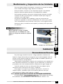
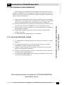
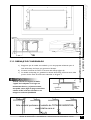
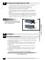
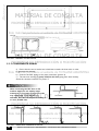
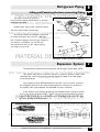
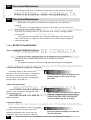
ÍNDICE 1. PREFACIO Página ............................................................................................................................................. 3 2. NOMENCLATURA ....................................................................................................................................... 3 3. INSTRUCCIONES DE SEGURIDAD ....................................................................................................... 4 4. RECIBIMIENTO E INSPECCIÓN DE LAS UNIDADES ..................................................................... 5 5. INSTALACIÓN ............................................................................................................................................. 5 5.1. RECOMENDACIONES GENERALES ......................................................................................... 5 5.2.PROCEDIMIENTOS BÁSICOS PARA INSTALACIÓN ........................................................... 6 5.3. INSTALACIÓN DE LA UNIDAD EVAPORADORA ............................................................... 7 5.3.1. RECOMENDACIONES GENERALES .......................................................................... 7 5.3.2. COLOCACIÓN EN EL LUGAR .................................................................................... 7 5.3.3. DRENO DE CONDENSADO ....................................................................................... 9 6. TUBERÍAS DE REFRIGERANTE .............................................................................................................. 10 6.1. SUSPENSIÓN Y FIJACIÓN DE LAS TUBERÍAS DE INTERCONEXIÓN ...................... 10 7. SISTEMA DE EXPANSIÓN ....................................................................................................................... 10 8. INSTALACIÓN ELÉCTRICA DE LA UNIDAD EVAPORADORA ................................................ 11 9. CIRCUITOS FRIGORÍGENOS ................................................................................................................. 12 10. INTER CONEXIONES ELÉCTRICAS ................................................................................................. 13 10.1. DIAGRAMA ELÉCTRICO DE LAS UNIDADES EVAPORADORAS ............................. 13 11. MANTENIMIENTO .................................................................................................................................. 14 11.1. GENERALIDADES ........................................................................................................................ 14 11.2. MANTENIMIENTO PREVENTIVO ......................................................................................... 14 11.3. MANTENIMIENTO CORRECTIVO ....................................................................................... 15 11.4. DETECCIÓN DE FUGAS .......................................................................................................... 15 11.4.1. MÉTODOS DE DETECCIÓN ................................................................................... 15 11.4.2. REPARACIÓN DE LA FUGA ..................................................................................... 16 11.5. LIMPIEZA INTERNA DEL SISTEMA ...................................................................................... 16 11.6. CUIDADOS GENERALES .......................................................................................................... 16 12. ANÁLISIS DE PROBLEMAS ..................................................................................................................... 17 13. PLANILLA DE MANTENIMIENTO PREVENTIVO ......................................................................... 18 14. CARACTERÍSTICAS TÉCNICAS .......................................................................................................... 19 15. TABLA Y CURVAS CAUDAL X P.E.D. PARA HEAVY-DUTY (CON CONDUCTOS) ........... 19 Surrey 1 Prefácio Este equipo es fruto de un arduo trabajo de investigación e ingeniería en conjunto con la experiencia de más de 40 años en la fabricación de acondicionadores de aire. Este manual está destinado a los técnicos debidamente entrenados y calificados, en el intento de auxiliar en los procedimientos de instalación y mantenimiento de la evaporadora. Cabe resaltar que cualquier reparación servicios pueden ser peligrosos si los realizan personas no habilitadas. Solamente profesionales entrenados deben instalar, dar arranque inicial y prestar cualquier mantenimiento a los equipos objeto de este manual. Dígitos 1 2 Código Ejemplo 4 2 3 4 5 6 B Q A 0 7 8 9 10 11 12 13 3 6 7 1 0 K U Dígitos 1 y 2 Tipo de Máquina 2 Dígito 13 Marca 42 - Evaporadora U - Surrey Digito 3 Chasis o Modelo Dígito 12 Opción / Feature B - Built In K - Sin control Dígito 4 Tipo del Sistema MATERIAL DE CONSULTA Unidad Evaporadora PROHIBIDA SU REPRODUCCIÓN O MODIFICACIÓN Nomeclatura Dígito 11 Tensión de Comando Q - Caliente / Frío 0 - Sin control Dígito 10 Fase Dígito 5 Actualización Proyecto A - Original sin revisión B - Primeira revisión C - Segunda revisión 1 - Monofásico Dígito 9 Tensión / Frecuencia Dígitos 6, 7 y 8 Capacidad 7 - 230V / 50Hz 036 - 36.000 BTU/h 057 - 57.000 BTU/h 072 - 72.000 BTU/h Este material pertenece al website de TOTALINE ARGENTINA www.totaline.com.ar MANUAL DE INSTALACIÓN Y MANTENIMIENTO / INSTALLATION AND MAINTENANCE MANUAL 3 Surrey 3 Instrucciones de Seguridad Las nuevas unidades evaporadoras fueron proyectadas para ofrecer un servicio seguro y confiable cuando se las opera dentro de las especificaciones previstas en proyecto. Sin embargo, debido a esta misma concepción, aspectos referentes a la instalación, arranque inicial y mantenimiento deben ser rigurosamente observados. · · · · · · Verifique los pesos y dimensiones de las unidades (ver ítem 14) para asegurarse un manejo adecuado y con seguridad. Sepa cómo manejar el equipo de oxiacetileno seguro. Deje el equipo en la posición vertical dentro del vehículo y también en el lugar de trabajo. Use nitrógeno seco para presurizar y verificar todos los sistemas. Use un buen regulador. Cuide de no exceder 200 psig de presión de test en los compresores rotativos. Antes de trabajar en cualquiera de las unidades desconecte siempre la alimentación de fuerza desenchufando de la unidad evaporadora del enchufe. Nunca introduzca las manos o cualquier otro objeto dentro de las unidades mientras el ventilador esté funcionando. Este material pertenece al website de TOTALINE ARGENTINA www.totaline.com.ar 4 MANUAL DE INSTALACIÓN Y MANTENIMIENTO / INSTALLATION AND MAINTENANCE MANUAL MATERIAL DE CONSULTA · PROHIBIDA SU REPRODUCCIÓN O MODIFICACIÓN · Mantenga el extintor de incendio siempre cerca al lugar de trabajo. Verifique el extintor periódicamente para cerciorarse que está con la carga completa y funcionando perfectamente. Cuando esté trabajando en el equipo esté atento siempre a todos los avisos de precaución contenidos en las etiquetas pegadas a las unidades. Siga siempre todas las normas de seguridad aplicables y use ropas y equipos de protección individual. Use guantes y lentes de protección cuando manipule las unidades o el refrigerante del sistema. · · · · · 4 Surrey Recibimiento y Inspección de las Unidades Para evitar daños durante el movimiento o transporte, no remueva el embalaje de las unidades hasta llegar al lugar definitivo de instalación. Evite que cuerdas, corrientes u otros dispositivos apoyen en las unidades. Respete el límite de apilado indicado en el embalaje de las unidades. Para mantener la garantía, evite que las unidades queden expuestas a posibles accidentes de obra, proporcionando su inmediato traslado para el lugar de instalación u otro lugar seguro. Al remover las unidades de los embalajes y retirar las protecciones de poliestireno expandido no descarte inmediatamente los mismos pues podrán servir eventualmente como protección contra polvo, u otros agentes nocivos hasta que la obra y/o instalación esté completa y el sistema pronto para entrar en operación. Instalación Recomendaciones Generales En primer lugar consulte las normas o códigos aplicables a instalación del equipo en el lugar seleccionado para asegurarse que el sistema idealizado estará de acuerdo con las mismas. Consulte por ejemplo la NB-3 de la ABNT Ejecución de Instalaciones Eléctricas de Baja Tensión. Haga también un planeamiento cuidadoso de la localización de las unidades para evitar eventuales interferencias con cualquier tipo de instalaciones ya existentes (o proyectadas), tales como instalación eléctrica, canalizaciones de agua, desagüe, etc. 5 MATERIAL DE CONSULTA FIGURA 1- MANEJO DE LAS UNIDADES PROHIBIDA SU REPRODUCCIÓN O MODIFICACIÓN Nunca suspenda o cargue la unidad evaporadora por el cambiador de calor. Asegure en las partes metálicas conforme figura 1. 5.1 Instale las unidades de forma que ellas queden libres de cualquier tipo de obstrucción de las tomas de aire de retorno o insuflación. Escoja lugares con espacios que posibilitan reparaciones o servicios de cualquier especie y posibiliten el paso de las tuberías (tubos de cobre que interconecten las unidades, hilado eléctrico y drenaje). Este material pertenece website TOTALINE ARGENTINA Recuerde que las unidadesaldeben estar de niveladas después de su instalación. Es imprescindible que la unidad evaporadora tenga línea hidráulica para drenaje www.totaline.com.ar del condensado. Esta línea hidráulica no debe tener diámetro inferior a 1/2". MANUAL DE INSTALACIÓN Y MANTENIMIENTO / INSTALLATION AND MAINTENANCE MANUAL 5 Surrey Se recomienda, el uso de starter código KAACS0201PTC para las unidades monofásicas de 36000 Btu/h, en casos donde, comprobadamente la tensión nominal fuera inferior a 208V. El starter se vende separadamente. Su Instalación está descrita en el esquema a seguir. TERMINAL DE LA CONTACTORA COMPRESOR - TERMINAL “S” UNIDAD EVAPORADORA SELECCIÓN DEL LUGAR ELECCIÓN DEL PERFIL DE LA INSTALACIÓN PERFORACIÓN EN LA PAREDY/POSICIÓN POSICIÓN DE LAS TUBERÍAS DE INTERCONEXIÓN INSTALACIÓN DE LATUBERÍA HIDRÁULICA PARA DRENAJE MONTAJE Este material pertenece al website de TOTALINE ARGENTINA www.totaline.com.ar 6 MANUAL DE INSTALACIÓN Y MANTENIMIENTO / INSTALLATION AND MAINTENANCE MANUAL MATERIAL DE CONSULTA 5.2 Procedimientos Básicos para Instalación PROHIBIDA SU REPRODUCCIÓN O MODIFICACIÓN STARTER KAACS020PTC Surrey 5.3 Instalación de la Unidad Evaporadora 5.3.1. RECOMENDACIONES GENERALES Antes de Ejecutar la instalación, lea con atención estas instrucciones a fin de quedar bien familiarizado con los detalles de la unidad. Las dimensiones y pesos se encuentran en el ítem 14 de este manual. Las reglas presentadas a continuación se aplican a todas las instalaciones. a) a) La unidad puede ser instalada solamente en la posición horizontal en el techo (figura 5). b) La unidad viene equipada con dos (2) soportes de fijación para montaje suspendida en el techo o fijada a la pared próxima. c) La figura 2 indica la posición de los tornillos de montaje en los soportes de fijación y las dimensiones principales. d) Instale los soportes de fijación en el techo a través del uso de los tornillos de montaje, tuercas volandas (figura 4). e) La posición de la unidad debe ser tal que permita la circulación uniforme del aire en todo el ambiente (figura 3). MATERIAL DE CONSULTA 5.3.2. COLOCACIÓN EN EL LUGAR PROHIBIDA SU REPRODUCCIÓN O MODIFICACIÓN Haga un plan cuidadoso de la ubicación de las unidades para evitar eventuales interferencias, con cualquier tipo de instalaciones ya existentes (o proyectadas), tales como instalaciones eléctricas, canalizaciones de agua y desagüe, etc. b) Instale la unidad donde ella quede libre de cualquier tipo de obstrucción de la circulación de aire tanto en la salida de aire como en el retorno de aire. c) Escoja un lugar con espacio suficiente que permita reparaciones o servicios de mantenimiento en general. d) El lugar debe posibilitar el paso de las tuberías (tubos del sistema, hilado eléctrico y drenaje). e) La unidad debe estar nivelada después a su instalación. Este material pertenece al website de TOTALINE ARGENTINA www.totaline.com.ar MANUAL DE INSTALACIÓN Y MANTENIMIENTO / INSTALLATION AND MAINTENANCE MANUAL 7 Surrey INCORRECTO CORRECTO INCORRECTO FIGURA 3 - POSICIÓN DE LA UNIDAD EVAPORADORA EN EL AMBIENTE FIGURA 4 - MONTAJE DEL SOPORTE DE FIJACIÓN Este material pertenece al website de TOTALINE ARGENTINA www.totaline.com.ar 8 MANUAL DE INSTALACIÓN Y MANTENIMIENTO / INSTALLATION AND MAINTENANCE MANUAL MATERIAL DE CONSULTA Posición de los tornillos de fijación PROHIBIDA SU REPRODUCCIÓN O MODIFICACIÓN FIGURA 2 - DIMENSIONES PARA INSTALACIÓN DE LA UNIDAD EVAPORADORA Surrey DRENO TECHO FIGURA 5 - MONTAJE EN EL TECHO 5.3.3. DRENAJE DE CONDENSADO a) Asegúrese que la unidad esté nivelada y con una pequeña inclinación para el lado del drenaje, de forma que garantice el drenaje. b) Conecte la tubería de PVC a la conexión del drenaje (figura 6). c) La unidad usa drenaje por gravedad. La tubería del drenaje, mientras tanto, debe poseer declive. Evite las situaciones indicadas en la figura 7. Cuando conecte la manguera de PVC o nipple de la máquina no lo haga con movimientos bruscos y o fuerza excesiva, esto podrá causar fugas. Si juzga conveniente caliente el PVC antes de conectarlo o use manguera con buena flexibilidad. TECHO FALSO MATERIAL DE CONSULTA TECHO PROHIBIDA SU REPRODUCCIÓN O MODIFICACIÓN FILTRO DEL AIRE TUBERÍA DEL DRENO FIGURA 6 Este material pertenece al website de TOTALINE ARGENTINA www.totaline.com.ar FIGURA 7 - SITUACIÓN DE DRENAJE INEFICAZ MANUAL DE INSTALACIÓN Y MANTENIMIENTO / INSTALLATION AND MAINTENANCE MANUAL 9 Surrey 6 Tuberías de Refrigerante 6.1 Suspensión y Fijación de las Tuberías de Interconexión Procure siempre fijar de manera conveniente las tuberías de interconexión a través de soportes o pórticos, preferentemente ambas conjuntamente. CONDUCTO DE INTERCONEXIÓN ELÉCTRICA (OPCIONAL) LÍNEA DE LIQUIDO LÍNEA DE SUCCIÓN Aíslelas utilizando goma de neopreno circular y después pase cinta de acabado alrededor (figura 8). CINTA AISLAMIENTO AISLAMIENTO TUBOS CINTA FIGURA 8 - TUBERÍAS DE INTERCONEXIÓN 7 Sistema de Expansión La expansión se realiza en la unidad evaporadora a través de un sistema denominado pistón o pistón. Este sistema con pistón, conforme figura 9, contiene una pequeña pieza con orificio calibrado fijo de fácil remoción en el interior de un nipple para conexión tuerca - pletina 3/8 en la línea de líquido. Las propiedades de aplicación del PISTÓN inciden desde el contenido más preciso del flujo de masa de gas refrigerante para el interior del evaporador, comparado por ejemplo al sistema de tubo capilar. Además de que, los PISTÓNS son de fácil mantenimiento. En el ciclo reverso (Refrigeración y Calentamiento) el sistema PISTÓN requiere un by-pass, o sea, dos piezas son colocadas en el interior del nipple, una haciendo el proceso de expansión y la otra como by-pass y viceversa, conforme la dirección del flujo de gas (modo refrigeración o calentamiento). SENTIDO PARA EXPANSIÓN SENTIDO DEL FLUJO DE REFRIGERACIÓN UNIDAD CONDENSADORA SENTIDO DEL FLUJO DE CALENTAMIENTO PISTÓN DE REFRIGERACIÓN PISTÓN DE CALENTAMIENTO UNIDAD EVAPORADORA Este material pertenece al website de TOTALINE ARGENTINA www.totaline.com.ar RETENTOR SENTIDO BY-PASS FIGURA 9 10 MANUAL DE INSTALACIÓN Y MANTENIMIENTO / INSTALLATION AND MAINTENANCE MANUAL RETENTOR MATERIAL DE CONSULTA PROHIBIDA SU REPRODUCCIÓN O MODIFICACIÓN Pruebe todas las conexiones soldadas y con pletina en cuanto a fugas (presión máxima de prueba: 200 psig). Use regulador de presión en el cilindro de Nitrógeno. Si fuera conveniente pase la interconexión eléctrica junto a la tubería de cobre, conforme figura 8. 8 Surrey Instalación Eléctrica de la Unidad Evaporadora El equipo posee unos bornes que posibilitan la conexión de diversos tipos de controles disponibles en el mercado. Haga la conexión eléctrica del equipo conforme se muestra en la figura de abajo. MATERIAL DE CONSULTA PROHIBIDA SU REPRODUCCIÓN O MODIFICACIÓN Conector 6-vías Aterrado Bornes Fuerza Neutro V1 - Rojo V2 - Azul V3 - Negro Este material pertenece al website de TOTALINE ARGENTINA www.totaline.com.ar MANUAL DE INSTALACIÓN Y MANTENIMIENTO / INSTALLATION AND MAINTENANCE MANUAL 11 Surrey 9 Circuitos Frigorígenos CAPACIDAD DE 36 A 72.000 Btu/h UNIDAD CONDENSADORA COMPRESOR UNIDAD EVAPORADORA LS ACUMULADOR DE SUCCIÓN EXCEP. 38MS CONDENSADORA EVAPORADORA LL PISTÓN COMPRESOR UNIDAD EVAPORADORA MUFLA VÁLVULA DE REVERSIÓN LL EVAPORADORA PISTÓN CONDENSADORA FLUJO DE REFRIGERACIÓN FLUJO DE CALENTAMIENTO Este material pertenece al website de TOTALINE ARGENTINA www.totaline.com.ar 12 MANUAL DE INSTALACIÓN Y MANTENIMIENTO / INSTALLATION AND MAINTENANCE MANUAL MATERIAL DE CONSULTA ACUMULADOR DE SUCCIÓN EXCEP. 38MS LS PROHIBIDA SU REPRODUCCIÓN O MODIFICACIÓN CONDENSER UNIT 10 Diagrama Eléctrico de las Unidades Evaporadoras 10.1 Surrey Inter Conexiones Eléctricas TORNILLO MATERIAL DE CONSULTA PROHIBIDA SU REPRODUCCIÓN O MODIFICACIÓN 42BC/Q 57/72 Este material pertenece al website de TOTALINE ARGENTINA www.totaline.com.ar MANUAL DE INSTALACIÓN Y MANTENIMIENTO / INSTALLATION AND MAINTENANCE MANUAL 13 Surrey 11 Mantenimiento 11.1 Generalidades Para evitar servicios de reparación innecesarios, verifique cuidadosamente los siguientes puntos: El aparato está correctamente conectado a la red principal, con todos los dispositivos manuales, y/o automáticos de maniobra/ protección del circuito adecuadamente conectado, sin interrupciones tales como: fusibles quemados, llaves abiertas, etc. · ¿El termostato está regulado correctamente para las condiciones deseadas? · ¿La llave interruptor / conmutador del ventilador está en la posición correcta? LIMPIEZA Limpie el condensador con un cepillo de pelo suave, si fuera necesario utilice también un aspirador de polvo para remover la suciedad. Después de esta operación utilice peine de aletas, en el sentido vertical de encima hacia abajo, para desaplastar las mismas. La acumulación de polvo obstruye y reduce el flujo de aire resultando en pérdida de capacidad. Limpie los gabinetes con una franela o paño suave embebido en agua tibia y jabón neutro. NO USE solventes, tetra-clorato de carbono, ceras conteniendo solvente o alcohol para limpiar las partes plásticas. CABLEADO Verifique todos los cables cuidando el deterioro y todos los contactos (terminales) eléctricos en referencia al ambiente y corrosión. MONTAJE Compruebe que la unidad esté firmemente instalada. CONTROLES Asegúrese de que todos los controles están funcionando correctamente y que la operación del aparato es normal. Vibraciones pueden causar ruidos indeseables. Este material pertenece al website de TOTALINE ARGENTINA DRENO www.totaline.com.ar Verifique taponamientos o aplastados en la manguera del dreno. Esto puede ocasionar un rebalse en la bandeja y consecuente fuga de condensado. 14 MANUAL DE INSTALACIÓN Y MANTENIMIENTO / INSTALLATION AND MAINTENANCE MANUAL MATERIAL DE CONSULTA 11.2 Mantenimiento Preventivo PROHIBIDA SU REPRODUCCIÓN O MODIFICACIÓN · Antes de ejecutar cualquier servicio de mantenimiento, desconecte la corriente eléctrica que alimenta el aparato a través de la unidad evaporadora. Debe hacerse en las situaciones en que algún componente impida el perfecto funcionamiento de la unidad. En estas ocasiones es necesario consultar los esquemas eléctricos colocados en la unidad. Surrey Mantenimiento Correctivo 11.3 Detección de Fugas 11.4 · Detector Electrónico (refrigerante + Nitrógeno) Investigue la fuga, pasando el sensor del aparato cerca a las conexiones, soldaduras y otros posibles puntos de fuga. Use baja velocidad en la dislocación del sensor. El aparato emite una señal auditiva y/o luminoso al pasar por el punto de fuga. · Detector Hálide-lamparilla (refrigerante + Nitrógeno) Procedimiento similar al anterior, pero en este caso al sensor se lo sustituye por una manguera que se conecta a una llama. Esta llama se torna verde en presencia de refrigerante halogenado (R11, R12, R22, etc ... ). · No inhale los gases resultantes de la quema del refrigerante pues son altamente tóxicos. Solución de agua y jabón Prepare una solución con jabón o detergente y esparza sobre las conexiones, soldaduras y otros posibles puntos de fuga. Aguarde por lo menos 1 minuto para verificar dónde se formará a burbuja. · MATERIAL DE CONSULTA 11.4.1. MÉTODOS DE DETECCIÓN PROHIBIDA SU REPRODUCCIÓN O MODIFICACIÓN Cuando haya sospecha de que exista una fuga en el circuito de refrigeración, se debe proceder de la siguiente forma: En caso de que haya presión suficiente de refrigerante en el sistema se puede pasar inmediatamente a la ubicación de la fuga por uno de los procesos indicados a seguir. Si, sin embargo, la presión residual estuviera muy baja, se debe conectar al sistema un cilindro de Nitrógeno. A continuación presurice el aparato hasta 200 psig. Dependiendo del método a ser utilizado se debe aumentar también una pequeña cantidad de refrigerante al sistema. Coloque el refrigerante antes del Nitrógeno. Cuidado en ambientes externos, el viento podrá dificultar la localización. Una solución muy pobre en jabón también es inadecuada pues no formará burbujas. Método de Inmersión pertenece alser website de TOTALINE ARGENTINA El MétodoEste de la material inmersión en tanque podrá utilizado para inspección en componentes www.totaline.com.ar No confunda burbujas de aire retiradas separados del aparato (especialmente serpentines). entre las aletas con fugas. En este caso, el componente debe ser presurizado a 200 psig. MANUAL DE INSTALACIÓN Y MANTENIMIENTO / INSTALLATION AND MAINTENANCE MANUAL 15 Surrey 11.4.2. REPARACIÓN DE FUGA Después de localizada la fuga, marque el lugar adecuadamente y retire la presión del sistema eliminando el refrigerante y/o Nitrógeno allá existentes. Prepare para hacer la soldadura (use soldadura Phoscopper o soldadura plata), ejecutándola con paso de Nitrógeno en el interior del tubo (durante la soldadura y a una baja presión), evitando la formación de óxidos en el interior del tubo. Compruebe que la reparación se realizó bien, presurizando y volviendo a comprobar el aparato. 11.5 Limpieza Interna del Sistema Daños a un nuevo compresor causados por fallas en la limpieza del sistema no están cubiertos por la garantía del producto. 11.6 Cuidados Generales · Mantenga el gabinete y las parrillas así como el área alrededor de la unidad lo más limpia posible. · Periódicamente limpie los serpentines con un cepillo suave. Si las aletas están muy sucias, utilice, en el sentido inverso del flujo de aire, chorro de aire comprimido o de agua a baja presión. Tome cuidado para no dañar las aletas. · Verifique el ajuste de conexiones, pletinas y demás fijaciones, evitando que aparezcan vibraciones, fuga y ruidos. · Asegúrese que los aislamientos de las piezas metálicas y tuberías están en el lugar correcto y en buenas condiciones. Este material pertenece al website de TOTALINE ARGENTINA www.totaline.com.ar 16 MANUAL DE INSTALACIÓN Y MANTENIMIENTO / INSTALLATION AND MAINTENANCE MANUAL MATERIAL DE CONSULTA PROHIBIDA SU REPRODUCCIÓN O MODIFICACIÓN A la quema de un motor eléctrico se la reconoce por el olor característico. Cuando un motor de un compresor hermético se quema, el aislado del rodamiento del estator forma carbono y lama ácida, en este caso, limpie el circuito del refrigerante antes de instalar un nuevo compresor. Instale un nuevo tubo capilar y filtro del condensador. Análisis de Problemas Tabla orientadora de posibles problemas en el equipo acondicionador de aire, con su posible causa y la corrección a ser tomada. PROBLEMA POSIBLES CAUSAS Motor de la unidad evaporadora funciona, pero no refrigera el ambiente eficientemente Instalación incorrecta o deficiente. Verifique el lugar de la instalación observando altura, lugar, incidencia de rayos solares, cortinas en frente al aparato, etc. Reinstale el aparato. Fuga de gas. Localice la fuga, repárela y proceda a operar nuevamente la unidad. Serpentines obstruidos por suciedad Destape el evaporador. Bajo voltaje de operación. Voltaje ofrecido debajo de la tensión mínima. Motor del ventilador con poca rotación. Verifique el capacitor de fase del motor del ventilador y el propio motor del ventilador, substituyéndolo si es necesario. Pistón trancado. Abra el nipple y limpie el pistón, en este caso generalmte el evaporador se queda bloqueado con hielo. Válvula de servicio cerrada o parcialmente cerrada. Abra la(s) válvula(s). Coloque el cable eléctrico adecuadamente en la fuente de alimentación. Proceda a la conexión directa del motor del ventilador, caso no funcione, sustituya el mismo. MATERIAL DE CONSULTA Rehaga el levantamiento de carga térmica y oriente al cliente y, si fuera necesario, cambie por un modelo de mayor capacidad. PROHIBIDA SU REPRODUCCIÓN O MODIFICACIÓN Capacidad térmica del aparato es insuficiente para el ambiente. Motores de los Cable eléctrico desconectado o con mal ventiladores no contacto. funcionan Motor del ventilador defectuoso. Evaporador bloqueado con hielo SOLUCIONES Surrey 12 Capacitor defectuoso. Use un ohmiómetro para detectar el defecto, si fuera necesario, cambie el capacitor. Llave selectora/mando remoto defectuoso. Use un ohmiómetro para detectar el defecto, si es necesario, cambie la llave selectora/mando remoto. Conexiones eléctricas incorrectas o cables rotos. Verifique la fijación, repare o sustituya la misma. Vea el esquema eléctrico del aparato. Hélice o turbina suelta o trabada. Verifique, fijándola correctamente. Pistón trancado. Vuelva a operar la unidad, abriendo el nipple. Conviene ejecutar limpieza en los componentes con chorros de R-22 o R-11 líquido. Fuga de gas. Elimine la fuga y cambie todo el gas refrigerante. Ruido excesivo Holgura en el eje/cojinete; de los motores de los Sustituya el motor del ventilador. ventiladores. durante el Tubería vibrando. Verifique el lugar generador del ruido y elimínelo. Piezas sueltas. Verifique, sujételas o fíjelas correctamente. Hélice o turbina desbalanceada o rota. Este material pertenece al website de Sustituya. TOTALINE ARGENTINA Instalación incorrecta. Normal. Mejore la instalación (refuerce las piezas que www.totaline.com.ar presentan estructura frágil). Oriente al cliente. MANUAL DE INSTALACIÓN Y MANTENIMIENTO / INSTALLATION AND MAINTENANCE MANUAL 17 Surrey 13 Planilla de Mantenimiento Preventivo DESCRIPCIÓN DE LOS SERVICIOS ÍTEM FRECUENCIA A B C 1o Inspección general en la instalación del equipo, cortocircuito de aire, distribución de insuflación en las unidades, bloqueo en la entrada y salida de aire del condensador. 2o Verifique instalación eléctrica. * 3o Lave y seque el filtro de aire. * 4o Mida tensión y corriente de funcionamiento y compare con la nominal. * 5o Mida tensión con rotor trabado y observe caída de tensión hasta que el protector se apague. 6o Verifique el ajuste de todos los terminales eléctricos de las unidades, evite posibles malos contactos. * 7o Verifique obstrucción de suciedad y aletas aplastadas. * 8o Verifique posibles taponamientos o aplastados en la manguera del drenaje. * 9o Haga la limpieza de los gabinetes. 10o Mida diferencial de temperatura. * 11o Verifique holgura del eje de los motores eléctricos. * 12o Verifique posición, fijación y balanceado de la hélice o turbina. * 13o Verifique operación del termostato. * 14o Mida presiones de equilibrio. * 15o Mida presiones de funcionamiento. * * B Trimestralmente C - Semestralmente Este material pertenece al website de TOTALINE ARGENTINA www.totaline.com.ar 18 MANUAL DE INSTALACIÓN Y MANTENIMIENTO / INSTALLATION AND MAINTENANCE MANUAL MATERIAL DE CONSULTA A Mensualmente * PROHIBIDA SU REPRODUCCIÓN O MODIFICACIÓN Código de Frecuencias: * 276 123456789 6 12345699 6 123456929 6 12333 45333 56333 78"8#$% 8"& 8+)7 ),- 613))43 8& & " 7&' 3 1 1 7 &8 " ( 7&' 66 6 6 8& && " *& 2 2 2 64 64 64 899 )66 &8'& & 989 &"&&8798 PISTÓN 0,6 5 FR (C K) / PISTÓN 0,6 1 CR & 0,67 FR (Y C ) 789 3789 35 6 626516 2626516 2626516 7&998&"#3&67 8"&98&97 789 36789 6 6! 82"& &&3&45 & .' 87 8 & 9/0&&9&1 1 52 625 6254 31 35 35 36kBTU/h Alta Média Baja Presión Caudal Presión Caudal Presión Caudal mmCA m³/h mmCA m³/h mmCA m³/h 2 1905 2 1407 2 1214 4 1783 4 1316 4 1136 6 1669 6 1232 6 1063 8 1480 8 1092 8 943 15 MATERIAL DE CONSULTA Tabla y Curvas Caudal X P.E.D para Heavy-Duty (con Conductos) PROHIBIDA SU REPRODUCCIÓN O MODIFICACIÓN +& 8 14 Surrey Características Técnicas 57/72kBTU/h Alta Média Baja Presión Caudal Presión Caudal Presión Caudal mmCA m³/h mmCA m³/h mmCA m³/h 2 2308 2 2159 2 1936 4 2160 4 2021 4 1812 6 2021 6 1891 6 1695 8 1792 8 1677 8 1504 Este material pertenece al website de TOTALINE ARGENTINA www.totaline.com.ar MANUAL DE INSTALACIÓN Y MANTENIMIENTO / INSTALLATION AND MAINTENANCE MANUAL 19 Surrey GRÁFICO CAUDAL x P.E.D. - 36KBTU/h www.totaline.com.ar 20 MANUAL DE INSTALACIÓN Y MANTENIMIENTO / INSTALLATION AND MAINTENANCE MANUAL MATERIAL DE CONSULTA Este material pertenece al website de TOTALINE ARGENTINA PROHIBIDA SU REPRODUCCIÓN O MODIFICACIÓN GRÁFICO CAUDAL x P.E.D. - 57/72KBTU/h Surrey INDEX 1. INTRODUCTION ....................................................................................................................................... 19 2. NOMENCLATURE ...................................................................................................................................... 21 3. SAFETY INSTRUCTIONS ......................................................................................................................... 22 4. RECEIVING AND INSPECTING THE UNITS .................................................................................... 22 5. INSTALLATION ........................................................................................................................................... 23 5.1. GENERAL RECOMMENDATIONS ........................................................................................... 23 5.2. BASIC INSTALLATION PROCEDURES ................................................................................... 23 5.3. INSTALLATION OF THE EVAPORATOR UNIT .................................................................... 24 5.3.1. GENERAL RECOMMENDATIONS ............................................................................ 24 5.3.2. POSITIONING ON SITE ............................................................................................... 24 PROHIBIDA SU REPRODUCCIÓN O MODIFICACIÓN 5.3.3. CONDENSATE DRAIN ................................................................................................. 25 6. REFRIGERANT PIPING ............................................................................................................................. 26 6.1. LIFTING AND FASTENING THE INTERCONNECTION PIPING ................................. 26 7. EXPANSION SYSTEM ................................................................................................................................ 26 9. FRIGORIGEN CIRCUITS .......................................................................................................................... 28 10. ELECTRIC INTERCONNECTIONS ................................................................................................... 29 10.1. ELECTRIC DIAGRAM OF THE EVAPORATOR UNITS .................................................... 29 11. MAINTENANCE ....................................................................................................................................... 30 11.1. GENERAL ........................................................................................................................................ 30 11.2. PREVENTIVE MAINTENANCE ............................................................................................... 30 11.3. CORRECTIVE MAINTENANCE ............................................................................................. 30 11.4. LEAK DETECTION ..................................................................................................................... 30 11.4.1. DETECTION METHODS ........................................................................................... 30 MATERIAL DE CONSULTA 8. ELECTRIC INSTALLATION OF THE EVAPORATOR UNIT ........................................................... 27 11.4.2. LEAK REPAIRS ................................................................................................................ 31 11.5. INTERNAL CLEANING OF THE SYSTEM ........................................................................... 31 11.6. GENERAL CARE .......................................................................................................................... 31 12. FAILURE ANALYSIS ................................................................................................................................... 32 13. PREVENTIVE MAINTENANCE SPREADSHEET ............................................................................ 33 14. TECHNICAL CHARACTERISTICS ...................................................................................................... 34 15. TABLE AND FLOW CURVES X A.S.P. FOR HEAVY-DUTY (WITH DUCTS) ........................... 34 Este material pertenece al website de TOTALINE ARGENTINA www.totaline.com.ar MANUAL DE INSTALACIÓN Y MANTENIMIENTO / INSTALLATION AND MAINTENANCE MANUAL 21 Surrey 1 Introduction This equipment is the result of a hard research and engineering work associated to more than 40 years of experience in the manufacturing of air conditioners. This manual is intended for duly trained and qualified technicians, and aims at helping them in the installation and maintenance of the evaporator. It is important to highlight that any repairs or services may be dangerous if performed by non-qualified personnel. Only trained professionals shall install, start up and service this equipment. Evaporator Unit Digits 1 2 Exemple of Code 4 2 3 4 5 B Q A 6 7 8 9 10 11 0 3 6 7 1 0 K U Digits 1 & 2 Type of Machine 12 13 Digit 13 Trademark 42 - Evaporator U - Surrey Digit 3 Chassis or Model Digit 12 Option / Feature B - Built In K - Without control Digit 4 Type of System Digit 11 Command Voltage Q - Heat / Cool 0 - Without control Digit 5 Project Updating Digit 10 Phase A - Original not reviewed B - First review C - Second review 1 - Single phase Digit 9 Voltage / Frequency Digits 6, 7 & 8 Capacity 7 - 230V / 50Hz 036 - 36,000 BTU/h 057 - 57,000 BTU/h 072 - 72,000 BTU/h Este material pertenece al website de TOTALINE ARGENTINA www.totaline.com.ar 22 MANUAL DE INSTALACIÓN Y MANTENIMIENTO / INSTALLATION AND MAINTENANCE MANUAL MATERIAL DE CONSULTA Nomenclature PROHIBIDA SU REPRODUCCIÓN O MODIFICACIÓN 2 3 Surrey Safety Instructions The new evaporator units were designed to offer a safe and reliable service when operated within the project specifications. However, due this same conception, aspects referring to the installation, initial start-up and maintenance shall be strictly observed. Keep the fire extinguisher always near the working site. Check the fire extinguisher periodically to ensure it is with the full charge and operating perfectly. · When working on the equipment observe the warnings on the labels fastened to the units. Always follow the applicable safety regulations and wear individual protection apparel and equipment. Wear gloves and safety goggles when handling the units or the system refrigerant. · · · · · MATERIAL DE CONSULTA · PROHIBIDA SU REPRODUCCIÓN O MODIFICACIÓN · Check the weight and dimensions of the units (see item 14) to guarantee a proper and safe handling. Learn how to handle the oxyacetylene equipment safely. Leave the equipment on the vertical position inside the vehicle and also at the working site. Use dry nitrogen to pressurize and check the whole system. Use a good regulator. Be careful not to exceed 200 psig of testing pressure in the rotary compressors. Before working on any unit, turn off the power supply unplugging the evaporator unit. Never insert the hands or any other object into the units while the fan is running. Este material pertenece al website de TOTALINE ARGENTINA www.totaline.com.ar MANUAL DE INSTALACIÓN Y MANTENIMIENTO / INSTALLATION AND MAINTENANCE MANUAL 23 Surrey 4 Receiving and Inspecting the Units · To prevent damages during the moving or transportation, do not remove the packaging of the units until arriving at the definitive installation site. · · · Prevent ropes, chains or any other devices from touching the units. Respect the piling limit indicated on the unit packaging. To keep the guarantee, do not let the units exposed to possible accidents and arrange their immediate transfer to the installation site or to any other safe location. · When removing the units from the packaging and the protections of expanded polystyrene do not dispose them immediately, since they may eventually serve as a protection against dust, or other damaging agents until the work and/or the installation is complete and the system ready to start the operation. 5 Installation 5.1 General Recommendations First, consult the regulations or codes applicable to the equipment. Check if the chosen location conforms to them. Consult, for example, ABNT´s NB-3: Performing Low-Voltage Electric Installations. Make a careful planning of the unit site to prevent eventual interferences from any kind of existing (or projected) installations, such as electric installation, water, sewage piping, etc. Install the units in a way that they are free from any kinds of obstruction for the return or insufflating air intakes. Choose locations with enough space to allow repairs or services of any kind and the passage of the piping (copper tubes to interconnect the units, electric wiring and drain). Remember that the units must be leveled after their installation. It Este is mandatory to provide a hydraulic line for condensate draining from the material pertenece al website de TOTALINE ARGENTINA evaporator unit. This hydraulic line shall not have a diameter smaller than 1/2". www.totaline.com.ar 24 MANUAL DE INSTALACIÓN Y MANTENIMIENTO / INSTALLATION AND MAINTENANCE MANUAL MATERIAL DE CONSULTA PICTURE 1- HANDLING THE UNITS PROHIBIDA SU REPRODUCCIÓN O MODIFICACIÓN Never lift or move the evaporator unit by the heat exchanger. Hold it on the metallic parts according to picture 1. Surrey It is advisable to use a starter, code KAACS0201PTC for single-phase units with 36,000 Btu/h, whenever the rated voltage is lower than 208V. The starter is sold in separate. Its installation is described on the diagram below. CONTACTOR TERMINAL COMPRESSOR - TERMINAL S MATERIAL DE CONSULTA PROHIBIDA SU REPRODUCCIÓN O MODIFICACIÓN STARTER KAACS020PTC Basic Installation Procedures 5.2 Evaporator Unit CHOOSING THE SITE CHOOSINGTHE INSTALATION PROFILE DRILLING ON WALL/POSITIONING POSITIONING OFTHE INTERCONNECTING PIPING INSTALATION OF THE HYDRAULIC PIPING TO DRAIN ASSEMBLY Este material pertenece al website de TOTALINE ARGENTINA www.totaline.com.ar MANUAL DE INSTALACIÓN Y MANTENIMIENTO / INSTALLATION AND MAINTENANCE MANUAL 25 Surrey 5.3 Installation of the Evaporator Unit 5.3.1. GENERAL RECOMMENDATIONS Before performing the installation, read carefully these instructions to get acquainted with the unit details. The dimensions and weight can be found in item 14 of this manual. The rules presented next apply to all installations. a) a) The unit can be installed only at the horizontal position on the ceiling (picture 5). b) The unit is equipped with two (2) fastening brackets for the assembly on the ceiling or on the next wall. c) Picture 2 shows the position of the assembly screws on the fastening brackets and the major dimensions. d) Install the fastening brackets on the ceiling with screws, washers, and nuts (picture 4). e) The position of the unit shall be such to allow the uniform air circulation throughout the room (picture 3). Este material pertenece al website de TOTALINE ARGENTINA www.totaline.com.ar 26 MANUAL DE INSTALACIÓN Y MANTENIMIENTO / INSTALLATION AND MAINTENANCE MANUAL MATERIAL DE CONSULTA 5.3.2. POSITIONING ON THE SITE PROHIBIDA SU REPRODUCCIÓN O MODIFICACIÓN Make a careful planning of the unit location to prevent eventual interferences with any existing (or projected) facilities such as electric installations, water and sewage piping, etc. b) Install the unit where it stays free from any kind of obstruction for the air circulation either at the outlet as at the air return. c) Choose a location with enough space that allows repair or maintenance services in general. d) The site shall allow the passage of the piping (system tubes, electric wiring and drain). e) The unit shall be leveled after its installation. Surrey OUTLET Position of the fastening screws WRONG MATERIAL DE CONSULTA PICTURE 2 - DIMENSIONS FOR THE INSTALLATION OF THE EVAPORATOR UNIT PROHIBIDA SU REPRODUCCIÓN O MODIFICACIÓN MACHINE CORRECT WRONG PICTURE 3 - POSITION OF THE EVAPORATOR UNIT IN THE ROOM PICTURE 4 - ASSEMBLY OF THE FASTENING BRACKET Este material pertenece al website de TOTALINE ARGENTINA www.totaline.com.ar MANUAL DE INSTALACIÓN Y MANTENIMIENTO / INSTALLATION AND MAINTENANCE MANUAL 27 Surrey MATERIAL DE CONSULTA PROHIBIDA SU REPRODUCCIÓN O MODIFICACIÓN Este material pertenece al website de TOTALINE ARGENTINA AIR FILTER www.totaline.com.ar CEILING DRAIN MATERIAL DE CONSULTA CEILING PICTURE 5 - ASSEMBLY ON THE CEILING SU REPRODUCCIÓN 5.3.3.PROHIBIDA CONDENSATE DRAIN O MODIFICACIÓN a) Ensure that the unit is leveled and a little bent towards the drain side, in order to guarantee the draining. Este material pertenece al website de TOTALINE ARGENTINA b) Connect the PVC piping to the drain connection (picture 6). c) The unit uses draining bywww.totaline.com.ar gravity. However, the drain piping must have declivity. Avoid the situations indicated on picture 7. When connecting the PVC hose or the machine nipple, do not employ rough movements or excessive strength since this may cause leaks. If you believe it is advisable, heat the PVC before connecting it or use a flexible hose. MATERIAL DE CONSULTA DRAIN PIPING FALSE CEILING PICTURE 6 PROHIBIDA SU REPRODUCCIÓN O MODIFICACIÓN Este material pertenece al website de TOTALINE ARGENTINA www.totaline.com.ar PICTURE 7 - INNEFICIENT DRAINING SITUATION 28 MANUAL DE INSTALACIÓN Y MANTENIMIENTO / INSTALLATION AND MAINTENANCE MANUAL 6.1 Lifting and Fastening the Interconnecting Piping MATERIAL DE CONSULTA Try always to fasten properly the interconnection piping with brackets or porches, preferably with both. ELECTRIC INTERCONECTION DUCT (OPTIONAL) LIQUID LINE PROHIBIDA SU REPRODUCCIÓN O MODIFICACIÓN SUCTION LINE Insulate them with circular neoprene rubber and use a tape around it (picture 8). TAPE EsteTest material pertenece al website de TOTALINE ARGENTINA all the welded and flanged connections INSULATION for leaks (maximum test pressure: www.totaline.com.ar 200 psig). Use a pressure gauge in the nitrogen cylinder. If you deem it convenient, pass the electric interconnection next to the copper piping, PIPES according to picture 8. INSULATION MATERIAL DE CONSULTA TAPE PICTURE 8 - INTERCONNECTION PIPING PROHIBIDA SU REPRODUCCIÓN O MODIFICACIÓN Expansion System 7 The expansion is performed at the evaporator unit through a system called piston. Este material de9, TOTALINE ARGENTINA This pertenece system with piston,alas website shown in picture contains a small part with a fixed calibrated hole, which can be easily removed, inside the nipple for the 3/8" flangewww.totaline.com.ar nut at the liquid line. The properties of the PISTON application provide a more accurate content of the refrigerant gas flow to the inside of the evaporator, compared, for example to the capillary tube system. Besides, the PISTONS are easy to maintain. In the reverse cycle (Cooling & Heating) the PISTON system requires a by-pass, that is, two parts are placed inside a nipple. One performs the expansion process and the other is used as a by-pass and vice-versa, depending on the direction of the gas flow (cooling or heating mode). MATERIAL DE CONSULTA EXPANSION DIRECTION PROHIBIDA SU REPRODUCCIÓN O MODIFICACIÓN FLOW DIRECTION IN HEATING FLOW DIRECTION IN COOLING COOLING PISTON CONDENSER UNIT HEATING PISTON EVAPORATOR UNIT Este material pertenece al website de TOTALINE ARGENTINA www.totaline.com.ar RETAINER RETAINER BY-PASS DIRECTION PICTURE 9 MANUAL DE INSTALACIÓN Y MANTENIMIENTO / INSTALLATION AND MAINTENANCE MANUAL 29 Surrey 6 Refrigerant Piping Surrey 8 Electric Installation of the Evaporator Unit The equipment has a terminal that allows connecting several kinds of controls available in the market. MATERIAL DE CONSULTA Make the electrical connection of the equipment as shown in the picture below. PROHIBIDA SU REPRODUCCIÓN O MODIFICACIÓN Este material pertenece al website de TOTALINE ARGENTINA www.totaline.com.ar 6-way connector MATERIAL DE CONSULTA Grounding PROHIBIDA SU REPRODUCCIÓN O MODIFICACIÓN Este material pertenece al website de TOTALINE ARGENTINA www.totaline.com.ar Power Terminal MATERIAL DE CONSULTA Neutral V1 - Red V2 - Blue V3 - Black PROHIBIDA SU REPRODUCCIÓN O MODIFICACIÓN Este material pertenece al website de TOTALINE ARGENTINA www.totaline.com.ar 30 MANUAL DE INSTALACIÓN Y MANTENIMIENTO / INSTALLATION AND MAINTENANCE MANUAL 9 CAPACITY: FROM 36 TO 72,000 Btu/h MATERIAL DE CONSULTA CONDENSER UNIT EVAPORATOR UNIT LS PROHIBIDA SU REPRODUCCIÓN O MODIFICACIÓN SUCTION ACCUMULATOR EXCEPT 38MS EVAPORATOR Este material pertenece al website de LL TOTALINE ARGENTINA CONDENSER www.totaline.com.ar CONDENSER UNIT EVAPORATOR UNIT MUFLE LS MATERIAL DE CONSULTA SUCTION ACCUMULATOR EXCEPT 38MS REVERSING VALVE LL EVAPORATOR PROHIBIDA SU REPRODUCCIÓN O MODIFICACIÓN CONDENSER COOLING FLOW HEATING FLOW Este material pertenece al website de TOTALINE ARGENTINA www.totaline.com.ar MATERIAL DE CONSULTA PROHIBIDA SU REPRODUCCIÓN O MODIFICACIÓN Este material pertenece al website de TOTALINE ARGENTINA www.totaline.com.ar MANUAL DE INSTALACIÓN Y MANTENIMIENTO / INSTALLATION AND MAINTENANCE MANUAL 31 Surrey Frigorigen Circuits Surrey 10 Electric Interconnections 10.1 Electric Diagram of the Evaporator Units MATERIAL DE CONSULTA PROHIBIDA SU REPRODUCCIÓN O MODIFICACIÓN SCREW CAPACITOR GROUND MOTOR EVAP. PHASE 1 PHASE 2 TERMINAL LOW SPEED MEDIUM SPEED HIGH SPEED Este material pertenece al website de TOTALINE ARGENTINA www.totaline.com.ar NOTES: MOTOR GROUND SHALL BE CONNECTED TO CHASSIS. GROUND CONNECTION MADE ON FIELD SHALL BE MADE ALSO TO CHASSIS. MATERIAL DE CONSULTA PROHIBIDA SU REPRODUCCIÓN O MODIFICACIÓN 42BC/Q Este material pertenece al website de TOTALINE ARGENTINA ONLY FOR UNITS www.totaline.com.ar MATERIAL DE CONSULTA PROHIBIDA SU REPRODUCCIÓN O MODIFICACIÓN Este material pertenece al website de TOTALINE ARGENTINA www.totaline.com.ar 32 MANUAL DE INSTALACIÓN Y MANTENIMIENTO / INSTALLATION AND MAINTENANCE MANUAL 11 General 11.1 MATERIAL DE CONSULTA To prevent unnecessary repair services, check carefully the following points: · Before performing any maintenance services, turn off the electric current that supplies the equipment through the evaporator unit. PROHIBIDA SU REPRODUCCIÓN O MODIFICACIÓN Is the equipment properly connected to the major network, with all the manual and/or automatic devices of maneuver/protection of the circuit properly connected, without interruptions: burnt fuses, open switches, etc.? Este material pertenece al website de TOTALINE ARGENTINA www.totaline.com.ar · Is the thermostat properly set for the desired conditions? · Is the contact breaker/switch of the fan in a correct position? Preventive Maintenance 11.2 MATERIAL DE CONSULTA CLEANING Clean the condenser with a soft brush and, if necessary, use a vacuum cleaner to remove the dirt. After this operation use a finned comb on the vertical direction, from the top to the bottom, to un-wrinkle them. The dust accumulation obstructs and reduces the airflow and may result in capacity loss. PROHIBIDA SU REPRODUCCIÓN O MODIFICACIÓN Clean thepertenece cabinet with a soft or with a cloth warm water and neutral Este material alcloth website de with TOTALINE ARGENTINA detergent. DO NOT USE solvents, carbon tetrachloride, and waxes containing www.totaline.com.ar solvents or alcohol to clean the plastic parts. WIRING Check all the cables for wear and all the electric contacts (terminals) for tightening and corrosion. ASSEMBLY MATERIAL DE CONSULTA Ensure that the unit is firmly installed. CONTROLS PROHIBIDA SU REPRODUCCIÓN O the MODIFICACIÓN Ensure that all controls are operating correctly and that operation of the equipment is normal. Vibrations may cause undesired noises. DRAIN Este material al clogged website deThis TOTALINE ARGENTINA Check if pertenece the drain hose is not or creased. may cause an overflow of the tray and consequent condensate leak. www.totaline.com.ar MANUAL DE INSTALACIÓN Y MANTENIMIENTO / INSTALLATION AND MAINTENANCE MANUAL 33 Surrey Maintenance Surrey 11.3 Corrective Maintenance It must be performed when a component is hindering the perfect operation of the unit. MATERIAL DE CONSULTA In these occasions it is necessary to consult the electric wiring of the unit. 11.4 Corrective Maintenance PROHIBIDA SU REPRODUCCIÓN O MODIFICACIÓN When there is a suspicious of a leak in the cooling circuit, one must do the following: In case there is enough refrigerant pressure in the system, one can look for the leak using one of the processes below. Este material pertenece al website de TOTALINE ARGENTINA If, however, the residual pressure is very low, one must connect a nitrogen cylinder to the system. www.totaline.com.ar Then pressurize the equipment up to 200 psig. Depending on the method to be used, a small amount of refrigerant must be added to the system. Put the refrigerant before the Nitrogen. 11.4.1. DETECTION METHODS MATERIAL DE CONSULTA Electronic Detector (refrigerant + Nitrogen) Look for the leaks, passing the sensor of the equipment next to connections, PROHIBIDA REPRODUCCIÓN OtheMODIFICACIÓN welding and otherSU possible leaking points. Use low speed at sensor displacement. The equipment transmits a sound and/or light sign when passing by the leaking point. Este material pertenece al website de TOTALINE ARGENTINA Halide-lamp Detector (refrigerant + Nitrogen) www.totaline.com.ar Procedure similar to the previous one. However in this case, the sensor is replaced by a Do not breathe the gases resulting from the hose that is connected to a flame. This flame burning refrigerant since they are very becomes green in the presence of halogenated poisonous. refrigerant (R11, R12, R22, etc ... ). Water and soap solution MATERIAL DE CONSULTA Prepare a solution with soap or detergent and apply it on the connections, welding and other possible leaking points. When in outside environments, the wind can make more difficult to find out the leak. A solution with little soap is also improper since the bubbles will not be formed. PROHIBIDA SU REPRODUCCIÓN O MODIFICACIÓN Wait, at least, one minute to see where the bubble will appear. Immersion Method Este material pertenece al website de TOTALINE ARGENTINA The Immersion Method in tanks can be used www.totaline.com.ar to inspect components separated from the Do not confound air bubbles removed from equipment (especially coils). In this case, the the fins with leaks. component must be pressurized at 200 psig. 34 MANUAL DE INSTALACIÓN Y MANTENIMIENTO / INSTALLATION AND MAINTENANCE MANUAL Surrey 11.4.2. LEAK REPAIR After the leak is found out, mark the location properly and remove the system pressure by the elimination of the existing refrigerant and/or Nitrogen. MATERIAL DE CONSULTA Prepare the welding (use Phoscopper or silver welding) and perform it with Nitrogen passage inside the tube (during the welding, and at a low pressure) avoiding the formation of oxides inside the pipe. PROHIBIDA SU REPRODUCCIÓN O MODIFICACIÓN Check if the repair is o.k. Pressurize and test the equipment again. Este material pertenece al website deCleaning TOTALINE ARGENTINA Internal of the System 11.5 www.totaline.com.ar A burnt motor is recognized by its typical smell. When a motor of a hermetic compressor burns, the insulation of the stator winding makes up carbon and acid mud. In this case, clean the refrigerant circuit before installing a new compressor. Install a new capillary tube and a condenser filter. MATERIAL DE CONSULTA Damages to a new compressor caused by failures in the system cleaning are not covered by the product warranty. PROHIBIDA SU REPRODUCCIÓN O MODIFICACIÓN General Care 11.6 · Keep the cabinet and the grids, as well as the area around the unit, as clean as possible. · www.totaline.com.ar From time to time, clean the coils with a soft brush. If the fins are very dirty, use compressed air or low-pressure water jet at the reverse direction to clean them. Be careful not to damage the fins. · Check if connections, flanges and other fixations are tightened, preventing the appearance of vibrations, leaks and noises. Este material pertenece al website de TOTALINE ARGENTINA MATERIAL DE CONSULTA · Ensure that the insulation of the metallic parts and piping are at the correct position and in good conditions. PROHIBIDA SU REPRODUCCIÓN O MODIFICACIÓN Este material pertenece al website de TOTALINE ARGENTINA www.totaline.com.ar MANUAL DE INSTALACIÓN Y MANTENIMIENTO / INSTALLATION AND MAINTENANCE MANUAL 35 Surrey 12 Failure Analysis Table of possible failures in the air conditioning equipment, with their possible causes and the correction to be adopted. MATERIAL DE CONSULTA FAILURE SOLUTIONS POSSIBLE CAUSES Remake the thermal load calculation and orient the customer. If required, change for a higher capacity PROHIBIDA SU REPRODUCCIÓN O MODIFICACIÓN model. The motor of the Thermal capacity of the equipment is not enough for the room. evaporator unit operates but the room is not Improper or inefficient installation. efficiently cooled. Check the installation site observing the height, location, sunrays, curtains in front of the equipment, etc. Reinstall the equipment. Este material TOTALINE ARGENTINA Findde out the leak, repair it and re-operate the unit. Gas leaks. pertenece al website Coils obstructed with dirt. Unblock the evaporator. www.totaline.com.ar Low operation voltage. Supplied voltage is lower than the minimum tension. Very low fan motor revolutions. Check the phase capacitor of the fan motor and the motor itself. Replace it if necessary. Locked piston. Open the nipple and clean the piston. In this case, the evaporator generally is blocked with ice. Closed or partially closed service valve. Open the valve(s). Disconnected cable or bad contact. Put the electric cable properly in the power supply. Defective fan motor. Perform the direct connection of the fan motor. In case it does not work, replace it. MATERIAL DE CONSULTA Motor fans do not run. PROHIBIDA SU REPRODUCCIÓN O MODIFICACIÓN Use an ohmmeter to detect the failure. If required, Defective capacitor. replace the capacitor. Defective selection switch /remote control. Use an ohmmeter to detect the failure. If necessary, replace the selective switch/remote control. wiring, repair or replace it. See the electric Este material pertenece alwires. websiteCheck dethe TOTALINE ARGENTINA Incorrect electric wiring or broken diagram of the equipment. Check and fix it properly. Loose or locked propeller or www.totaline.com.ar turbine. Evaporator blocked with ice. Excessive noise during the operation. Locked piston. Re-start the unit and open the nipple. It is advisable to clean the components with R-22 or R-11 liquid jets. Gas leaks. Correct the leak and change all the refrigerant gas. Clearance in the shaft/bearings of the fan motors. Replace the fan motor. Vibration in the piping. Find out the location generating the noise and eliminate it. Loose parts. Check, wedge or fasten them properly. Imbalanced or broken propeller or turbine. Replace. MATERIAL DE CONSULTA Enhance the installation (reinforce the parts with Incorrect installation. PROHIBIDA SU REPRODUCCIÓN O MODIFICACIÓN fragile structure). Normal. Orient the customer. Este material pertenece al website de TOTALINE ARGENTINA www.totaline.com.ar 36 MANUAL DE INSTALACIÓN Y MANTENIMIENTO / INSTALLATION AND MAINTENANCE MANUAL ITEM 1ST MATERIAL DE CONSULTA SERVICE DESCRIPTION FREQUENCY A B C General inspection of the equipment installation, air short circuit, insufflation distribution for the units, blocked air inlet and outlet of the condenser. * Check the electric installation. PROHIBIDA SU REPRODUCCIÓN O MODIFICACIÓN 2 * ND 3RD Wash and dry the air filter. 4TH Measure the voltage and operating current and compare it with the rated one. * Este material pertenece al website de TOTALINE ARGENTINA Measure the voltage with the locked rotor and observe the voltage drop until the protector turns off. 5TH 6TH Check if all the electric terminals www.totaline.com.ar for the units are tightened. Prevent possible bad contacts. 7TH Check if there are not obstructions due to dirt and creased fins. 8TH Check possible obstructions or creasing in the drain hose. 9TH Clean the cabinets. * * * * * * MATERIAL DE CONSULTA 10TH Measure the temperature differential. * 11TH Check the electric motor shaft for clearances. * 12TH Check positioning, fixation and balance of the propeller or turbine. * PROHIBIDA SU REPRODUCCIÓN O MODIFICACIÓN 13TH Check the thermostat operation. * 14TH Measure balance pressures. * Measure operation pressures. 15 material Este pertenece al website de TOTALINE ARGENTINA * TH Frequency Codes: A Monthly B Quarterly C - Every six months www.totaline.com.ar MATERIAL DE CONSULTA PROHIBIDA SU REPRODUCCIÓN O MODIFICACIÓN Este material pertenece al website de TOTALINE ARGENTINA www.totaline.com.ar MANUAL DE INSTALACIÓN Y MANTENIMIENTO / INSTALLATION AND MAINTENANCE MANUAL 37 Surrey 13 Preventive Maintenance Spreadsheet Surrey 14 Technical Characteristics 276 MATERIAL DE CONSULTA 123456789 6 12345699 6 123456929 6 12333 45333 56333 &878 /45" 79770#7"#*1 % 613##43 & 3 1 1 7 & 6 % 66 6 6 2 2 2 64 64 PROHIBIDA SU REPRODUCCIÓN O MODIFICACIÓN 9 #7 & 88 /+ 64 8) #66 Este material pertenece al website de TOTALINE ARGENTINA .79899 & PISTON 0.65 FR (CK) / PISTON 0.61 C R & 0.67 FR (Y C ) 789 3789 35 6 626516 2626516 2626516 8)* 8 * 7+)8),- %8&989*% www.totaline.com.ar 63 %8%8& '( 2) 7 8 1 !" 523 625 6254 31 35 35 89# $ 15 789 36789 6 MATERIAL DE CONSULTA Table & Flow Curves X A.S.P for Heavy-Duty (with Ducts) PROHIBIDA SU REPRODUCCIÓN O MODIFICACIÓN 36kBTU/h High Medium Low Pressure Flow Pressure Flow Pressure Flow 2 1905 2 1407 www.totaline.com.ar 2 1214 4 1783 4 1316 4 1136 6 1669 6 1232 6 1063 8 1480 8 1092 8 943 Este material pertenece al website ARGENTINA mmCA m³/h mmCA m³/h de TOTALINE mmCA m³/h 57/72kBTU/h MATERIAL DE CONSULTA High Medium Low Pressure Flow Pressure Flow Pressure Flow mmCA m³/h mmCA m³/h mmCA m³/h 4 2160 4 2021 4 1812 6 2021 6 1891 6 1695 PROHIBIDA SU REPRODUCCIÓN O 2MODIFICACIÓN 2 2308 2 2159 1936 Este material pertenece al website de TOTALINE ARGENTINA 8 1792 8 1677 8 1504 www.totaline.com.ar 38 MANUAL DE INSTALACIÓN Y MANTENIMIENTO / INSTALLATION AND MAINTENANCE MANUAL Surrey FLOW x A.S.P CHART - 36KBTU/h MATERIAL DE CONSULTA PROHIBIDA SU REPRODUCCIÓN O MODIFICACIÓN Este material pertenece al website de TOTALINE ARGENTINA www.totaline.com.ar MATERIAL DE CONSULTA PROHIBIDA SU REPRODUCCIÓN O MODIFICACIÓN FLOW x A.S.P CHART - 57/72KBTU/h Este material pertenece al website de TOTALINE ARGENTINA www.totaline.com.ar MATERIAL DE CONSULTA PROHIBIDA SU REPRODUCCIÓN O MODIFICACIÓN Este material pertenece al website de TOTALINE ARGENTINA www.totaline.com.ar MANUAL DE INSTALACIÓN Y MANTENIMIENTO / INSTALLATION AND MAINTENANCE MANUAL 39 256.08.596 - B - 11/05 MATERIAL DE CONSULTA PROHIBIDA SU REPRODUCCIÓN O MODIFICACIÓN Este material pertenece al website de TOTALINE ARGENTINA www.totaline.com.ar MATERIAL DE CONSULTA PROHIBIDA SU REPRODUCCIÓN O MODIFICACIÓN Este material pertenece al website de TOTALINE ARGENTINA www.totaline.com.ar MATERIAL DE CONSULTA PROHIBIDA SU REPRODUCCIÓN O MODIFICACIÓN Este material pertenece al website de TOTALINE ARGENTINA www.totaline.com.ar