1
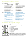
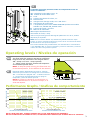
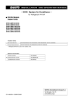
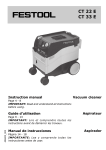
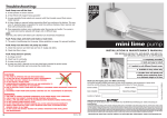
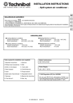
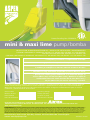
Patent Pending No. 0129096.4 mini & maxi lime pump / bomba INSTallaTIoN & maINTeNaNce maNual / maNual De INSTalacIÓN Y maNTeNImIeNTo for mINI lIme moDelS / moDeloS: aSP-ml-115, aSP-ml-230, aSP-mlS-115, aSP-mlS-230, aSP-ml-lG24, aSP-mlS-lG24, aSP-mlf-115, aSP-mlf-230 for maxI lIme moDelS / moDeloS: aSP-maxlS-115, aSP-maxlS-230, aSP-maxlf-115, aSP-maxlf-230 • Completely reversible / Completamente reversible • Quick and easy to install / Rápido y fácíl de instalar • 3 models to suit different lineset covers / 3 modelos para adaptarse a distintas cubiertas de tubería de cobre • Available in ivory and white / Disponible en colores blanco Y marfil • Quietly and reliably pump condensate to a maximum height of 26 feet (Mini Lime) and 49 feet (Maxi Lime) / Bombean el aqua de condensado hasta una altura maxima de 26 pies (Mini Lime) y 49 pies (Maxi Lime) de manera silenciosa y confiables This manual provides complete instructions for installation and maintenance which should be carefully followed. Please record following information for future reference: / agradecemos su compra de la nueva bomba mini o maxi lime. este manual proporciona las instrucciones que deben de seguirse cuidadosamente para la correcta instalacion y manteniemento de la bomba: Serial number: Número de serie: operating voltage: Voltaje operativo: Date installed: fecha de instalaciÛn: location of pump: ubicación de la bomba: Imported and Distributed by: / Importado y distributado para: 1244 Davol Street, Fall River MA 02720 Tel: 800-324-7832 Fax: 508 673-0115 email:[email protected] www.airtecproducts.com Product Warranty The manufacturer disclaims all implied and express warranties, including the implied warranty of merchantability and the implied warranty of fitness for a particular purpose, except as follows: This condensate product purchased by you concurrently is unconditionally warranteed to be free from defects in material and workmanship under normal use for a period of two years from date of purchase, providing it is installed and operated strictly in accordance with the manufacturer’s installation instructions. If the product is found to be defect or otherwise fails in normal use, you may return it for replacement. all freight charges for the return of the product shall be borne by you. The manufacturer will pay outgoing freight charges for the replacement product. Defective product returned to the factory prepaid will be repaired or replaced free of charge. replacement product will, to the extent such product is then available in the manufacturer’s inventory, be of a similar type of color and kind. manufacturer retains the right to substitute product if the replacement product does not conform in terms of color, type and specifications to the original product if no longer available. This warranty does not cover replacement labor or any cost, claim or incident to any defect nor does it cover any consequential damages. The sole liability of the manufacturer under this warranty is limited to the replacement of defective product. Product damaged by improper use, accident, neglect, alteration, abuse or improper installation is excluded from this warranty. Manufactured by: Aspen Pumps Apex Way Hailsham East Sussex BN27 3WA United Kingdom website: www.aspenpumps.com aSPeN/05/10 Zco892 Technical Data / Datos técnicos ENG ES • Power SuPPlY: mini lime: 115V ac 0.16a 13.5w 60HZ 230V ac 0.10a 15w 60HZ 24 V ac 0.7a 16w 60HZ maxi lime: 115V ac 0.23a 18w 60HZ 230V ac 0.10a 15w 60HZ • 3a volt-free alarm wires, N/o N/c contacts rated @ 5a inductive @ 230V ac • mini lime: continuously rated maxi lime: Non-continuously rated – operating time: 10 mins on / 5 mins off • mini lime: class I appliance maxi lime: class II appliance • Hall effect electronic water level sensors • Thermally protected pump • fully potted electronics • maximum water temperature: 104ºf • alImeNTacIÓN elÉcTrIca: mini lime: 115V ca 0.16a 13.5w 60HZ 230V ca 0.10a 15w 60HZ 24 V ca 0.7a 16w 60HZ maxi lime: 115V ca 0.23a 18w 60HZ 230V ca 0.10a 15w 60HZ • cables de alarma de 3a sin voltios, contactos N/o N/c con capacidad nominal a 5a inductivo a 230 V ca. • mini lime: a cóndición continua, maxi lime: funcionamiento discontinuo marcha 5 minutos / Paro 5 minutos • mini lime: aparato clase I maxi lime: aparato clase II • Sensor de nivel de agua electrónico tipo efecto Hall • Bomba protegida térmicamente • el sistema de circuitos electrónicos esta • SouND leVel: mini lime: 23dB(a) maxi lime: 35dB(a) @ 39” • eTl® listed • caPacITY: mini lime: 3.7 GPH @ zero head, 0.8 GPH @26ft head maxi lime: 5.8 GPH @ zero head, 0.8 GPH @49ft head • maxImum recommeNDeD HeaD: mini lime: 26ft maxi lime: 49ft • Discharge tube 1/4” i.d • Gravity inlet • Handles minisplits up to: mini lime: 30,000 BTu/Hr maxi lime: 60,000 BTu/Hr totalmente sellado (encapsulados) • Temperatura máxima del agua: 104ºf • NIVel De SoNIDo: mini lime: 23 Decibeles maxi lime: 35 Decibeles @ 39” • listada por eTl® • caPacIDaD: mini lime: 3.7 GPH @ cero pies de carga, 0.8 GPH @ 26 pies de carga maxi lime: 5.8 GPH @ cero pies de carga, 0.8 GPH @ 49 pies de carga • mÁxIma carGa HIDroSTaTIca recomeNDaDa: mini lime: 26 pies maxi lime: 49 pies • manguera de descarga de 1/4” de d.i. • entrada de gravedad • Puede trabajar con minisplits hasta: mini lime: 30,000 BTu/Hr maxi lime: 60,000 BTu/Hr Kit includes / El paquete incluye * ENG * Check that all components are present before starting installation. 4 1a. 1b. 2. 3. 4. 5. 6. 7. mini lime Pump assembly or 1b maxi lime Pump assembly elbow 31” lineset cover ceiling plate 20” 5/8” i.d. green connector hose evaporator flashing 2 couplers for aspen Slimline series (for models aSP-ml-115, aSP – ml 230, aSP-ml-lG24 only) 8. wallplugs and screws 9. Installation manual 10. warning label 11. 1 amp inline fuse 3 3 2 7 *1/4” vinyl discharge hose is not included and must be supplied on site. 2 1a 2 5 6 1b NoTE: for models aSP-ml-115, aSP-ml-230 and aSP-ml-lG24 in the aSPeN SlImlINe series, additional couplers and 31” lengths of duct are available as spare parts. for models aSP-mlS-115, aSP-mlS-230 and aSP-mlS-lG24 in the SlImDucT SD77 and lINeHIDe cD 75 series and aSP-mlf-115 and aSP-mlf-230 in the forTreSS lD92 series, additional couplers, fittings and lengths of duct are available as spare parts. ES * Comprobar que estén presentes todos los componentes antes de iniciar la instalación. * 4 1a. 1b. 2. 3. 4. 5. 6. 7. unidad de bomba mini lime o 1b unidad de bomba maxi lime codo cubierta de tuberÌa de cobre, 31” Placa de techo manguera de drenage verde, 20” x 5/8” de d.i. Vierteaguas del evaporador 2 acopladores para la serie aSPeN SlImlINe (Solamente modelos aSP-ml-115, aSP-ml-230, aSP-ml-lG24 8. Tapones de pared y tornillos 9. manual de instalación 10. etiqueta de advertencia 11. fusible en linea, 1 amp 3 3 2 7 *No se incluye la manguera de descarga de plástico de 1/4” de d.i., debera adquirirse por separado. 2 5 1a NoTA: Para los modelos aSP-ml-115, aSP-ml-230 y aSP-ml-lG24 serie aspen Slimline, se ofrecen acopladores adicionales y tramos de 31” de cubierta de tuberÌa de cobre Slimline como piezas de repuesto. Para modelos aSP-mlS-230 y aSP-mlS-lG24, serie Slimduct SD77 o linehide cD75 o serie forTreSS lD92, se ofrecen acopladores y accesorios adicionales y tramos de cubierta de cobre como piezas de repuesto. 1b 6 operating levels / Niveles de operación ENG The float inside the reservoir operates at 3 different heights which are illustrated in the diagram below. 3/8” – Pump is off. 3/4” – Pump operates. 1” – Safety switch operates, switches off evaporator and activates optional alarm. NoTE: To stop the pump running, the float must rest in the lowest position, on the bottom of the reservoir. ES el flotador dentro del depósito funciona en 3 alturas diferentes que se ilustran en el diagrama a continuación. 3/8” – la bomba est· apagada. 3/4” – la bomba funciona. 1” – el interruptor de seguridad funciona, apaga la evaporador y activa la alarma opciónal. NoTA: Para detener la bomba en funcionamiento, el flotador debe descansar en la posición mas baja, en el fondo del depósito. 1” 3 ” 3 ” /4 /8 Performance Graphs / Graficas de comportamiento 80 MINI LIME 40 we Do NoT recommeND oPeraTING aBoVe 26 ft HeaD 30 No recomeNDamoS fuNcIoNar SoBre 26 pies de carGa 20 10 0 0 1 2 3 uS GalloNS Per Hour / GaloNeS eSTaDouNIDeNSeS Por Hora 4 HeaD IN feeT / carGa eN PIeS HeaD IN feeT / carGa eN PIeS 50 MAxI LIME 60 40 we Do NoT recommeND oPeraTING aBoVe 49 ft HeaD No recomeNDamoS fuNcIoNar SoBre 49 pies de carGa 20 10 0 0 1 2 3 4 5 6 7 uS GalloNS Per Hour / GaloNeS eSTaDouNIDeNSeS Por Hora Do NoT RUN PUMP DRY, SERIoUS DAMAGE WILL oCCUR AND INVALIDATE WARRANTY. No HAGA FUNCIoNAR LA BoMBA EN SECo, oCURRIRÁN DAÑoS GRAVES QUE DEJARÁN NULA LA GARANTÍA. 3 Important notes / Notas importantes ENG ES ENG SIZING oF DISCHARGE HoSE uSING DIScHarGe HoSe oTHer THaN SIZe SPecIfIeD wIll maTerIallY affecT PuBlISHeD DaTa aND maY reSulT IN lower PerformaNce. DIMENSIoNAMIENTo DE LA MANGUERA DE DESCARGA el uSo De uNa maNGuera De DeScarGa De DImeNSIoNeS DIfereNTeS a laS recomeNDaDaS afecTara SIGNIfIcaTIVameNTe loS DaToS PuBlIcaDoS aSI como el DeSemPeÑo. NoISE all aSPeN mINI PumPS oPeraTe QuIeTlY, HoweVer, uNDer cerTaIN coNDITIoNS wHere aN exTremelY low amBIeNT NoISe leVel IS PreSeNT, THe SouND of THeIr INTermITTeNT oPeraTIoN maY STIll Be PerceIVeD aS NoISY. for THIS reaSoN, exTreme cauTIoN SHoulD Be exercISeD wHeN SelecTING PumPS for areaS wHere NoISe caN Be a ProBlem aND THe PumP SHoulD alwaYS Be SITeD ouTSIDe THe SeNSITIVe area. ALWAYS CONFIRM ACCEPTABLE NOISE LEVEL BEFORE INSTALLING ANY CONDENSATE PUMP IN A BEDROOM OR OTHER NOISE SENSITIVE AREA. coNSulT aIrTec for furTHer INformaTIoN aND for DeTaIlS of alTerNaTIVe PumPING meTHoDS. ES RUIDo ToDaS laS mINIBomBaS aSPeN fuNcIoNaN eN SIleNcIo; SIN emBarGo, Bajo cIerTaS coNDIcIoNeS, cuaNDo loS NIVeleS De ruIDo amBIeNTe SeaN exTremaDameNTe BajoS, el SoNIDo De Su oPeracIÓN INTermITeNTe PueDe Que Se PercIBa como ruIDoSo. Por eSTa raZÓN, Se DeBer TeNer Sumo cuIDaDo al SeleccIoNar BomBaS Para areaS DoNDe ruIDo PueDe eSTar uNa ProBlema Y la BomBa SIemPre Se DeBe colocar fuera Del area SeNSIBle. SIEMPRE CONFIRME QUE EL NIVEL DE RUIDO ES ACEPTABLE ANTES DE INSTALAR CUALQIER BOMBA DE CONDENSADOS EN UN DORMITORIO U OTRO AREA SENSIBLE AL RUIDO. coNSulTe a aIrTec Para maYor INformacIÓN Y oBTeNer DeTalleS De loS mÉToDoS De BomBeo alTerNaTIVoS. ENG ES ENG ES PoWER SUPPLY lINe VolTaGe mINI & maxI lIme PumPS are DeSIGNeD To oPeraTe aT eITHer 115 or 230 VolTS ac, 60HZ wITH a ToleraNce of + or – 10%. IN BuIlDINGS wIreD for 208 VolTS, 230 VolT PumPS SHoulD oPeraTe NormallY ProVIDeD THIS IS a True 208 VolT SuPPlY. HoweVer uSa Power GeNeraTIoN NormS PermIT a ToleraNce of +10% aND –15% aND If THe acTual Power SuPPlIeD To THe PumP IS Below 208 VolTS, IT caNNoT oPeraTe aT full caPacITY, wIll TeND To oVerHeaT aND maY BurN ouT PremaTurelY. You are STroNGlY aDVISeD To coNfIrm THaT THe VolTaGe oN SITe IS wITHIN oPeraTING raNGe Before INSTallING THe PumP aS our warraNTY DoeS NoT coVer DamaGe cauSeD BY INSuffIcIeNT Power SuPPlY. If IN DouBT, coNSulT aIrTec for furTHer DeTaIlS. ALIMENTACIÓN ELÉCTRICA laS BomBaS mINI Y maxI lIme De alTa VolTaje eSTÁN DISeÑaDa Para oPerar a 115 o 230 VolTIoS ca, 60 HZ coN uNa ToleraNcIa De +/- 10%. eN eDIfIcacIoNeS coN INSTalacIoNeS elÉcTrIcaS Para 208 VolTIoS laS BomBaS De 230 VolTS DeBeN De oPerar NormalmeNTe, SIemPre Y cuaNDo el SumINISTro elecTrIco real Sea De 208 VolTIoS. SIN emBarGo laS NormaS De GeNeracIÓN eN uSa PermITeN uNa ToleraNcIa De +10% Y -15% Por lo Que SI el SumINISTro elÉcTrIco eSTuVIera Por DeBajo De 208 VolTIoS, laS BomBaS No PoDraN oPerar a Su caPacIDaD ToTal, Y TeNDerÁN a SoBrecaleNTarSe Y QuIZaS QuemarSe PremaTurameNTe. eS alTameNTe acoNSejaBle Que Se coNfIrme Que el VolTaje eN el SITIo eSTÈ DeNTro Del raNGo De oPeracIÓN aNTeS De la INSTalacIÓN De laS BomBaS, como NueSTra GaraNTÍa No cuBre DaÑoS cauSaDoS Por INSufIcIeNcIaS eN el SumINISTro elÉcTrIco, SI HaY DuDaS al reSPecTo faVor De coNSulTar a aIrTec Para mÁS DeTalleS. PREVENTIoN oF SIPHoNING eNSure THaT eND of DIScHarGe HoSe IS HIGHer THaN waTer leVel IN eVaPoraTor DraIN PaN. If coNDeNSaTe DIScHarGe PoINT muST Be lower THaN DraINPaN THeN 1/4” DIScHarGe HoSe from PumP muST emPTY INTo a larGer DIameTer DraIN PIPe aT a HIGHer leVel THaN DraINPaN. THIS joINT muST INcorPoraTe aN aIr Break To PreVeNT SIPHoNING. for full DeTaIlS oN SIPHoNING, coNSulT aSPeN PuBlIcaTIoN: GuIDelINeS for correcT INSTallaTIoN of DIScHarGe HoSING, oN laST PaGeS of THIS maNual. PREVENCIÓN DEL EFECTo SIFoN cercIÓreSe De Que el exTremo De la maNGuera De DeScarGa eSTÈ eN uN NIVel mÁS alTo Que el NIVel Del aGua eN la BaNDeja De DeSaGÜe Del eVaPoraDor. SI el PuNTo De DeScarGa De aGua De coNDeNSacIÓN DeBe eSTar maS aBajo Que la BaNDeja De DeSaGÜe, la maNGuera De DeScarGa De 1/4” ProVeNIeNTe De la BomBa DeBe VacIarSe eN uNa TuBerÌa De DeSaGÜe Que TeNGa uN DIÁmeTro maYor Y eSTÈ eN uN NIVel mÁS alTo Que la BaNDeja. eSTa uNIÓN DeBe INcorPorar uN eSPacIo De aIre Para eVITar el SINfoNaje. SI DeSea maYoreS DeTalleS SoBre el SINfoNaje, falSe ceIlING / TecHo falSo coNSulTe la PuBlIcacIÓN De aSPeN: PauTaS Para eND of la correcTa INSTalacIÓN aIr Break / DIScHarGe HoSe / eSPacIo Del exTremo Del De la maNGuera De aIre maNGuera De DeScarGa, INcluIDa eN DeScarGa ToP of BreaTHer ulTImo PaGINaS De eSTÈ TuBe / maNual. ParTe SuPerIor Del TuBo reSPIraDor 4 waTer leVel IN DraIN TraY / NIVel De aGua eN la BaNDeja De DeSaGÜe Del eVaPoraDor Checklist / Lista de verificación ENG ITEM 1 DESCRIPTIoN Does pump voltage conform with evaporator supply voltage? ITEM DESCRIPTIoN 8 Is maximum head within pump limits? 9 Is discharge hose sized at 1/4” i.d. as per manufacturer’s instructions? 2 Is actual power input sufficient to drive pump? 3 Is pump permanently energized regardless of evaporator operation? 10 Is discharge hose watertight? Is pump level? 4 Is fuse installed? 11 Is float in position? 5 Is overflow switch (gray and purple wires) correctly wired into communication wire to ensure unit will not operate in case of pump failure or blockage? 12 13 Is magnet facing upwards on float? 14 Is filter present in reservoir? 15 Has provision been made to prevent siphoning? 16 Is drain discharge hose clear of restrictions? 17 Is intake hose watertight? 18 Is breather tube installed and free of restrictions? 19 Is reservoir tightly clipped onto pump? 6 Is piping & wiring in accordance with manufacturer’s instructions? 7 Is pump correctly sized to handle condensate output of evaporator? ES ParTIDa 1 2 DeScrIPcIN ¿cumple el voltaje de la bomba con el voltaje de suministro del evaporador? ¿Se recibe alimentación suficiente para accionar la bomba? 3 ¿está la bomba energizada permanentemente sin considerar la operación del evaporador? 4 5 ¿está instalado el fusible? ¿está el interruptor de derrames (alambres gris y morado) cableado correctamente al alambre de comunicación para garantizar que la unidad no funcione en caso de falla o bloqueo de la bomba? ¿cumplen las tuberÌas y cableado con las instrucciones del fabricante? 6 7 ¿Tiene la bomba el tamaño correcto para procesar la cantidad de agua de condensación del evaporador? ParTIDa 8 9 10 11 12 13 14 15 16 17 18 19 DeScrIPcIN ¿Se encuentra la carga hidrostática máxima dentro de los lÌmites de la bomba? ¿está la manguera de descarga el tamaño de 1/4”de d.i. de acuerdo con las instrucciones del fabricante ¿es hermética la manguera de descarga? ¿está nivelada la bomba? ¿está el flotador en su posición? ¿está el imán dispuesto hacia arriba en el flotador? ¿está el filtro presente en el depósito? ¿Se han tomado las medidas para evitar el sinfonaje? ¿está la manguera de descarga del desagüe libre de obstrucciones? ¿está hermética la manguera de entrada? ¿está instalada el tubo respirador, y es libre de obstrucciones? ¿está el depósito firmemente unido a la bomba? Product Safety / Seguridad de producto ENG • cauTIoN: The mini lime & maxi lime Pumps have been evaluated for use with water only. • warNING: risk of electric shock. These pumps have not been investigated for use in swimming pool or marine areas. • The means for isolation must be incorporated in the fixed wiring in accordance with wiring regulations. • ensure the pump is disconnected from the mains supply before carrying out any adjustments or servicing. ES • PrecaucIoN: las bombas mini lime y maxi lime han sido evaluada para utilizarse solamente con agua. • aDVerTeNcIa: Peligro de descarga eléctrica. estas bombas no han sido probada en applicaciones de piscinas o zonas marinas. • los metodos de aislamiento deben incorporarse en el cableado fijo de acuerdo con las regulaciones de cableado. • revise que la bomba estè desconectada de la red principal antes de llevar cabo ningun ajuste o servicio. • If the supply cord is damaged, it must be replaced with a special cord or assembly available from the manufacturer or it’s service agent. • Do not run these pumps dry. • always ensure the metal magnet in the float is facing upwards. • always ensure the pump is level. • These Pumps are ideal for most working and living environments. They are not recommended where the environment is oily or particularly dusty. • acceptable for indoor use only. • Non-submersible pumps. • Si el cable de alimentación se estropea debe ser reemplazado por un cable original, suministrado por el fabricante o su distribuidor. • No haga funcionar estas bombas en seco. • asegurarse siempre de que el imán de metal en el flotador esté apuntado hacia ariba. • asegurarse siempre de que la bomba esté nivelada. • las bombas estan ideal para la mayorÌa de los ambientes de trabajo y vivienda. No se recomienda para ambientes con mucho pulvo o aceite. • Solo es acceptable el uso en interiores • Bombas no sumergible. 5 Installation Wall-mounted Lineset Cover – A Instalación Montado en la pared Cubierta de tuberÌa de cobre – A THIS SECTIoN CoVERS oNLY ASP-ML-115, ASP-ML-230 oR ASP-ML-LG24 PUMPS FoR ASPEN SLIMLINE SERIES. ESTA SECCIoN APPLICAR SoLo HASTA BoMBAS ASP-ML-115, ASP-ML-230 o ASP-ML-LG24 PARA LA SERIE ASPEN SLIMLINE. 1 ENG Select left A or right B hand side of evaporator forBlineset, drain & electrical connections. ES Seleccione el lado izquierdo A o derecho B del evaporador para conexiones de tuberÌa de B A cobre, de drenaje y eléctricas. B A 2 ENG Disassemble elbow. Place back part of elbow flat on wall at least 4” away from evaporator to allow space for flashing. line up bottom of elbow with bottom of evaporator unit, make sure elbow is plumb, and secure to wall using screws and plugs provided. mINImum 4” / ES Desarme el codo. Ponga la parte posterior del codo contra la pared al menos a 4” de distancia del evaporador para permitir espacio para el vierteaguas. alinee la parte inferior del codo con la parte inferior de la unidad del evaporador, revise que el codo esté a plomo, y asegure a la pared usando los tornillos y tapones provistos. 3 ENG Insert 1 coupler into opening of elbow facing evaporator. ES Inserte 1 acoplador en la abertura del codo apuntando al evaporador. 6 mÌNImo 4” muST Be leVel / DeBe eSTar NIVelaDo Installation Wall-mounted Lineset Cover – A Instalación Montado en la pared Cubierta de tuberÌa de cobre – A 4 ENG cut length of lineset cover to suit gap between evaporator and centreline of coupler, if necessary, trim exposed end of lineset cover to fit profile of evaporator. Disassemble lineset cover and fit bottom half between coupler and evaporator. Secure to wall using screws and plugs provided. CUT TO LENGTH AND TRIM IF NECESSARY / CORTAR AL LARGO Y AJUSTA SI ES NECESARIO ES corte la longitud de la cubierta de tuberÌa de cobre con el fin de adaptarse al espacio entre el evaporador y la linea central del acoplador, si es necesario, ajusta el extremo exposo del cubierta de cobre para conforma con el profil del evaporador. Desarme la cubierta de la tuberÌa de cobre y ajuste la mitad inferior entre el acoplador y el evaporador. asegure a la pared usando los tornillos y tapones provistos. 5 ENG Insert second coupler into other opening of elbow. ES Inserte el segundo acoplador en la otra abertura del codo. 6 ENG couPlerS / acoPlaDoreS measure distance between centreline of top coupler and ceiling, and cut length of lineset cover to suit. Disassemble lineset cover and fit bottom half onto wall between top coupler and ceiling. ensure this is plumb and secure to wall using screws and plugs provided. ES mida la distancia entre la lÌnea central del acoplador superior y el techo, y corte la longitud de la cubierta de tubería de cobre con el fin de adaptarla a ella. Desarme la cubierta de tubería de cobre y ajuste la mitad inferior en la pared entre el acoplador superior y el techo. asegúrese de que esté a plomo y fÌjela a la pared usando los tornillos y tapones provistos. falSe ceIlING / TecHo falSo cuT To leNGTH corTar al larGo 7 Installation Wall-mounted Lineset Cover – A Instalación Montado en la pared Cubierta de tuberÌa de cobre – A 7 ENG Temporarily remove both couplers from the elbow. ES retire temporalmente ambos acopladores del codo. 8 ENG cut out area of ceiling above lineset cover. ES corte el área del techo arriba de la cubierta de tubería de cobre. 9 ENG INSTallaTIÓN INSTrucTIoNS (for lINeSeT coVerS a aND B) coNTINueD IN SecTIoN calleD ‘INSTallaTIoN – PumP aSSemBlY’. (PG 11) ES laS INSTruccIoNeS De INSTalacIÓN (Para cuBIerTaS De TuBerÌa De coBre a Y B) coNTINúa eN la SeccIÓN Que Se llama ‘INSTalacIÓN – eNSamBlaje De la BomBa’. (PG 11) 8 Installation Wall-mounted Lineset Cover – B Instalación Montado en la pared Cubierta de tubería de cobre – B THIS SECTIoN APPLIES oNLY To THE FoLLoWING PUMPS: ASP-MLS-115 & ASP-MLS-230 FoR SLIMDUCT SD77 & LINEHIDE CD 75 SERIES. ASP-MLF-115, ASP-MLF-230 FoR FoRTRESS LD92 SERIES. ESTo SECCIoN APPLICA SoLo HASTA LoS SIGUENTE BoMBAS: ASP-MLS-115 & ASP-MLS-230 PARA SLIMDUCT SD77 Y LINEHIDE CD 75 SERIE. ASP-MLF-115, ASP-MLF-230 PARA FoRTRESS LD92 SERIE. 1 ENG Select left A or right B hand side of evaporator forBlineset, drain & electrical connections. ES B Seleccione el lado izquierdo A o derecho B del evaporador para conexiones de tubería de cobre de A drenaje y eléctricas. A 2 B ENG Disassemble elbow. Place back part of elbow flat on wall at least 4” away from unit to allow space for flashing. line up bottom of elbow with bottom of evaporator unit, make sure elbow is plumb, and secure to wall using screws and plugs provided. MINIMUM 4” / MINIMUM MÌNIMO 4” 2" ES 3 Desarme el codo. Ponga la parte posterior del codo contra la pared al menos a 4” de MUST BE LEVEL MUST BE DEBE ESTAR distancia de la unidad para permitir espacio LEVEL NIVELADO para el vierteaguas. alinee la parte inferior del codo con la parte inferior de la unidad del evaporador, revise que el codo estè a plomo, y asegure a la pared usando los tornillos y tapones provistos. ENG cut length of lineset cover to suit gap between evaporator and elbow, allowing for 3/4"protrusion into elbow. If necessary, trim exposed end of lineset cover to fit profile of evaporator. Disassemble lineset cover and fit bottom half onto wall between elbow and evaporator. Secure to wall using screws and plugs provided. CUT TO LENGTH +3/4" AND TRIM IF NECESSARY / CORTAR AL LARGO +3/4"Y AJUSTA SI ES NECESARIO ES corte la longitud de la cubierta de tubería de cobre con el fin de adaptarla al espacio entre el evaporador y el codo, tomando en cuenta la protuberancia de 3/4"hacia el codo. Si es necessario, ajusta el extremo exposo del cubierta de cobre para conforma con el profil del evaporador. Desarme la cubierta de tubería de cobre y ajuste la mitad inferior en la pared entre el codo y el evaporador. asegure a la pared usando los tornillos y tapones provistos. 9 Installation Wall-mounted Lineset Cover – B Instalación Montado en la pared Cubierta de tubería de cobre – B 4 ENG measure distance between elbow and ceiling, allowing for 3/4"protrusion into elbow, cut length of lineset cover to fit. Disassemble lineset cover and fit bottom half onto wall between elbow and ceiling. ensure this is plumb and secure to wall using screws and plugs provided. FALSE TECHO FALSO FALSECEILING CEILING //TECHO FALSO 90º CUT TO LENGTH + 3/4" CUT TO LENGTH CORTAR AL LARGO CORTAR AL LARGO + 3/4" ES mida la distancia entre el codo y el techo, tomando en cuenta la protuberancia de 3/4" hacia el codo, corte la longitud de la cubierta de tubería de cobre a fin de adaptarla. Desarme la cubierta de tubería de cobre y ajuste la mitad inferior en la pared entre el codo y el techo. asegúrese de que esté a plomo y fÌjela a la pared usando los tornillos y tapones provistos. 5 ENG cut out area of ceiling above lineset cover. ES corte el área del techo arriba de la cubierta de tubería de cobre. 6 ENG INSTALLATION INSTRUCTIONS (FOR LINESET COVERS A AND B) CONTINUED IN SECTION CALLED ‘INSTALLATION – PUMP ASSEMBLY’. (PG 11) ES LAS INSTRUCCIONES DE INSTALACIÓN (PARA CUBIERTAS DE TUBERÌA DE COBRE A Y B) CONTINúA EN LA SECCIÓN QUE SE LLAMA ‘INSTALACIÓN – ENSAMBLAJE DE LA BOMBA’. (PG 11) 10 Installation – Pump Assembly and wiring Instalación – Ensamblaje de la Bomba y Cableado 1 ENG locate pump in back part of elbow. ES Sitúe la bomba en la parte posterior del codo. 2 3 ENG measure distance between reservoir and drain outlet hose of evaporator, allowing 3/4” extra to slip over evaporator drain fitting. cut green pump inlet hose to correct length. ES mida la distancia entre el depósito y la manguera de salida de drenaje del evaporador, permitiendo 3/4” extra para instalar encima del accesorio de drenaje del evaporador. corte la manguera verde de entrada de la bomba al largo correcto. CUT TO LENGTH + 3/4” ENG ES connect pump inlet to evaporator drain hose outlet with cut to length green inlet hose and ensure tight fit. CORTAR A LARGO+3/4” Y conecte la entrada de la bomba a la salida de la manguera de drenaje del evaporador con manguera verde cortado a la longitud y asegure un ajuste firme. 11 Installation – Pump Assembly and wiring Instalación – Ensamblaje de la Bomba y Cableado 4 5 ENG for mINI lIme: connect 1/4” i.d. vinyl discharge hose to barbed reducing connector at end of green discharge hose from pump and secure with a cable tie. for maxI lIme: 1/4” i.d. discharge hose from pump is insulated for first 39” to eliminate vibration, Do NoT REMoVE INSULATIoN. connect 1/4” i.d. vinyl discharge hose to connector at end of this insulated hose and secure with a cable tie. for mINI aND maxI lIme: Do NoT USE DISCHARGE HoSE LARGER THAN 1/4” id. ES Por mINI lIme: conecte la manguera de descarga de plástico de 1/4” de d.i. al conector/redactor en el extremo del manguera de descarga verde del bomba y asegurela con un sujetador plástico. Por maxI lIme: la manguera de descarga de plástico de 1/4” de d.i. desde la bomba es aislar por el primero 39” para eliminar la vibracion, No QUITARLo EL AISLAMIENTo. conecte la manguera de descarga de 1/4” de d.i. al conector en el extremo de la esta manguera aislamiento y asegurela con un sujetador plástico. Por mINI Y maxI lIme: No LA USE UNA MANGUERA DE DESCARGA MAS GRANDE QUE 1/4” de d.i. ENG fit breather tube onto breather outlet on top of pump and ensure top of tube is above water level in drain tray. NoTE: BREATHER TUBE IS CRITICAL To CoRRECT oPERATIoN oF PUMP AND MUST REMAIN FREE oF RESTRICTIoNS AT ALL TIMES BreaTHer TuBe / TuBo reSPIraDor ES encaje el tubo respirador en la tapa del bomba y asegurese que el tope del tubo esté sobre el máximo de nivel de agua en la bandeja de desagüe. NoTA: TUBo RESPIRADoR ES CRITICo PARA LA oPERACIÓN CoRRECTo DE LA BoMBA Y PUEDE ESTAR LIBRE DE oBSTRUCCIoNES EN ToDo MoMENTo 6 ENG channel discharge hose up through lineset cover to an appropriate drain point. avoid restrictions which can kink or compress hose. Do NoT USE DISCHARGE HoSE LARGER THAN 1/4” id 1/4” DIScHarGe HoSe / maNGuera De DeScarGa De 1/4” De d.i. aIr GaP / eSPacIo De aIre ES canalice la manguera de descarga arriba a través de la cubierta de cobre a un punto de drenaje adecuado. evite las restricciones que pueden doblar o comprimir la manguera. No LA USE UNA MANGUERA DE DESCARGA MAS GRANDE QUE 1/4” de d.i. 12 falSe ceIlING / TecHo falSo Installation – Pump Assembly and wiring Instalación – Ensamblaje de la Bomba y Cableado 7 Wiring / Cableado ENG CoNFIRM MAIN PoWER SUPPLY IS ISoLATED. THreaD Power caBle THrouGH eVaPoraTor To TermINaTe aT INcomING Power TermINalS. coNNecT Power aND oVerflow alarm wIreS accorDING To releVaNT DIaGram aND aTTacH warNING laBel To froNT of TermINal coVer. Do NoT USE A SEPARATE 115 or 230 VoLT oUTLET To PoWER PUMP AS THIS IS NoT FAIL SAFE AND MAY CAUSE AN oVERFLoW. WIRING: (1) check that pump voltage conforms with evaporator voltage and that actual voltage supplied is sufficient to drive pump. (2) wire pump power cable to incoming power terminals in evaporator so pump is permanently energized regardless of evaporator operation. (3) connect inline fuse (1 amp) into one of the incoming power wires to pump. (4) connect high level/overflow alarm, by removing communication wire from condenser from it’s terminal in evaporator and connecting it to gray wire from pump with a wirenut (or crimped butt connector where mandated). (5) connect purple wire to communication terminal in evaporator. This will prevent unit from operating in case of blockage or pump failure. Note this circuit can carry a maximum of 5 amps. If external alarm is required, connect N/o orange wire to alarm device as per detailed wiring diagram from our website. If no alarm is required, isolate orange wire with a wirenut. Some evaporators provide numbered terminals for connection of the gray and purple overflow alarm wires directly into the PcB, refer to relevant factory approved diagrams for correct wiring instructions. most Vrf systems e.g. city multi, eco-I, Vrf III and multi-V require constant communication between all evaporators in the system so the communication wire cannot be used as part of the overflow alarm, refer to relevant factory approved diagrams for correct wiring instructions. NoTe: coNNecTIoN of THe HIGH leVel/oVerflow SwITcH IS maNDaTorY aND faIlure To Do So wIll INValIDaTe PumP warraNTY! ES CoNFIRME QUE LA FUENTE DE ALIMENTACIÓN PRINCIPAL ESTÈ AISLADA. TIeNDa el caBle De alImeNTacIÓN Por el eVaPoraDor De moDo Que lleGue a loS TermINaleS eNTraNTeS De alImeNTacIÓN. coNecTe loS alamBreS De eNerGÍa Y De la alarma De Derrame SeGúN el DIaGrama PerTINeNTe Y aDHIera la eTIQueTa De aDVerTeNcIa eN la ParTe DelaNTera De la cuBIerTa Del TermINal. No USE ToMAS INDEPENDIENTES DE 115 ó 230 VoLTIoS PARA ALIMENTAR LA BoMBA, YA QUE ÉSTAS No SoN A PRUEBA DE FALLAS Y PUEDEN CAUSAR DERRAMES. CABLEADo: (1) Verifique que el voltaje de la bomba coincida con el del evaporador y que el voltaje real suministrado sea suficiente para accionar la bomba. (2) Tienda el cable de alimentación de la bomba a los terminales entrantes en el evaporador de modo que la bomba cuente con energía permanentemente, sin importar la operación del evaporador. (3) conecte el fusible en línea (1 amp) en uno de los cables entrantes de alimentación de la bomba. (4) conecte la alarma de alto nivel/derrame, quitando el cable de comunicación del condensador desde su terminal en el evaporador y conectándolo al cable gris proveniente de la bomba con una tuerca de cable (o conector engarzado donde ello sea obligatorio).(5) conecte el cable morado al terminal de comunicación en el evaporador. esto evitará que la unidad opere en caso de bloqueo o fallas en la bomba. observe que este circuito puede soportar un máximo de 5 amperios. Si no requiere de la alarma, se debera aislar el cable naranja con una tuerca de cable. algunos evaporadores cuentan con las terminales marcadas o numeradas, para la conexión directa en la (tablilla de circuito impreso) PcB, de los cables morado y gris de la alarma de sobre nivel, consulte los diagramas aprobados de fábricante para las correctas instrucciónes de alambrado y/o conexionado. la mayoría de los sistemas Vrf (flujo Variable de refrigerante) como city multi, eco-I, Vrf III and multi-V requieren de una comunicación constante entre todos los evaporadores del sistema por lo que el cable de comunicación no puede ser usado como parte de la alarma de sobre nivel , consulte los diagramas aprobados de fábricante para las correctas instrucciones de alambrado y/o conexionado. NoTa: la coNexIoN Del INTerruPTor Por alTo NIVel/Derrame eS fuNDameNTal Y SI No Se realIZa, Se INValIDara la GaraNTIa De la BomBa! 13 Installation – Pump Assembly and wiring Instalación – Ensamblaje de la Bomba y Cableado white blanco incoming 115V CA power terminals permanently live entrantes de 115V CA terminales de aliment permanentemente activos N black negro L 3 ground tierra G green verde G green verde incoming 208/230V AC power terminals permanently live entrantes de 208/230V CA terminales de aliment permanentemente activos G black negro red rojo 1 amp fuse 1 amp fusible pump bomba communication wire cable de comunicación 3 G purple (N/C) morado (norm. cerr.) 5 amps max 5 amp. máx. line 2 línea 2 orange wire – do not use, isolate with wire nut cable naranja – no la use, aislar con una tuerca de cable L2 3 L1 L2 gray common gris común 5 amps max 5 amp. máx. L1 green verde terminal block in evaporator bloque de terminales en evaporador wire nut or crimp tuerca o engarce red rojo black negro ground tierra line 1 línea 1 communication wire cable de comunicación black negro white blanco pump bomba purple (N/C) morado (norm. cerr.) 5 amps max 5 amp. máx. live activo neutral neutro 1 amp fuse 1 amp fusible gray common gris común 5 amps max 5 amp. máx. orange wire – do not use, isolate with wire nut cable naranja – no la use, aislar con una tuerca de cable terminal block in condenser bloque de terminales en condensador L terminal block in condenser bloque de terminales en condensador N ground tierra 3 G wire nut or crimp tuerca o engarce MAxI LIME 208 / 230V AC / CA 3 L communication wire cable de comunicación pump bomba gray common gris común 5 amps max 5 amp. máx. black negro N green verde ground tierra 1 amp fuse 1 amp fusible white blanco terminal block in evaporator bloque de terminales en evaporador black negro wire nut or crimp tuerca o engarce 3 G purple (N/C) morado (norm. cerr.) 5 amps max 5 amp. máx. L1 L2 MAxI LIME 115V AC / CA G green verde terminal block in evaporator bloque de terminales en evaporador orange wire – do not use, isolate with wire nut cable naranja – no la use, aislar con una tuerca de cable incoming 115V CA power terminals permanently live entrantes de 115V CA terminales de aliment permanentemente activos L2 3 red rojo pump bomba L1 line 2 línea 2 green verde ground tierra black negro white blanco 1 amp fuse 1 amp fusible red rojo black negro ground tierra line 1 línea 1 3 G communication wire cable de comunicación L purple (N/C) morado (norm. cerr.) 5 amps max 5 amp. máx. N live activo neutral neutro terminal block in evaporator bloque de terminales en evaporador MINI LIME 208 / 230V AC / CA incoming 208/230V AC power terminals permanently live entrantes de 208/230V CA terminales de aliment permanentemente activos terminal block in condenser bloque de terminales en condensador MINI LIME 115V AC / CA terminal block in condenser bloque de terminales en condensador 7 wire nut or crimp tuerca o engarce gray common gris común 5 amps max 5 amp. máx. orange wire – do not use, isolate with wire nut cable naranja – no la use, aislar con una tuerca de cable *THESE ARE TYPICALLY THE CoMMUNICATIoNS TERMINALS IN SINGLE AND MULTIZoNE SYSTEMS. VRF SYSTEMS ARE WIRED DIFFERENTLY, REFER To FACToRY APPRoVED DIAGRAMS FoR CoRRECT WIRING INSTRUCTIoNS. *TÍPICAMENTE ESTÁS SoN TERMINALES DE CoMUNICACIÓN EN SISTEMAS DE UNA ZoNA Y MULTI-ZoNA. LoS SISTEMAS VRF(FLUJo VARIABLE DE REFRIGERANTE) SoN ALAMBRADoS DE MANERA DIFERENTE, CoNSULTE LoS DIAGRAMAS APRoBADoS DE FÁBRICANTE PARA LAS CoRRECTAS INSTRUCCIoNES DE ALAMBRADo Y/o CoNExIoNADo. NOTE: NO GROUND IS REQUIRED FOR MAXI LIME PUMPS AS THEY ARE CLASS II APPLIANCES. NOTA: NO SE REQUIERE PUESTA A TIERRA PARA BOMBAS MAXI LIME, PUES SE TRATA DE APARATOS CLASE II. THESE ARE GENERIC DIAGRAMS FOR REFERENCE PURPOSES ONLY AS WIRING PROTOCOLS VARY FROM ONE MINISPLIT MANUFACTURER TO ANOTHER. ÉSTOS SON DIAGRAMAS GENÉRICOS SÓLO PARA FINES DE REFERENCIA, YA QUE LOS PROTOCOLOS DE CABLEADO VARÍAN ENTRE LOS FABRICANTES DE UNIDADES MINISPLIT. 14 facTorY aPProVeD wIrING DIaGramS for moST moDelS of all major mINISPlIT BraNDS caN Be fouND oN our weBSITe aT www.airtecproducts.com or call 1 800 324-7832 for onsite assistance. loS DIaGramaS De caBleaDo aProBaDoS Por la fÁBrIca Para ToDoS loS PrINcIPaleS moDeloS De marcaS De uNIDaDeS mINISPlIT Se PueDeN eNcoNTrar eN NueSTro SITIo weB: www.airtecproducts.com o bien puede llamar al 1 800 324-7832 para solicitar asistencia en terreno. Installation – Pump Assembly and wiring Instalación – Ensamblaje de la Bomba y Cableado 8 ENG TeST PumP oPeraTIoN BY PourING waTer INTo eVaPoraTor DraIN PaN. PumP maY Be NoISY oNlY wHIle aIr IS exPelleD DurING INITIal STarT-uP. IF NoISE PERSISTS AFTER START-UP, THIS INDICATES A SIPHoNING oR AIR LEAKAGE PRoBLEM, Do NoT RUN PUMP! cHeck THaT all coNNecTIoNS are waTerTIGHT To elImINaTe aIr IN HoSeS. refer To “PreVeNTIoN of SIPHoNING” SecTIoN oN PaGe 4 aND To DeTaIleD “GuIDelINeS for correcT INSTallaTIoN of DIScHarGe HoSING” oN laST PaGeS of THIS maNual. refer alSo To TrouBleSHooTING GuIDe oN PaGe 17. ES comProBar el fuNcIoNamIeNTo De la BomBa VerTIeNDo aGua eN la BaNDeja De DeSaGÜe Del eVaPoraDor. la BomBa PueDe Ser ruIDoSo SolameNTe mIeNTraS Se exPele aIre DuraNTe el arraNQue INIcIal. SI PERSISTE EL RUIDo DESPUES DEL ARRANQUE, EL INDICAR UNA PRoBLEMA DE SINFoNAJE o FUGAS DE AIRE, No HAGA FUNCIoNAR LA BoMBA! comProBar Que ToDoS loS coNexIoNeS eSTeN HermÉTIcaS Para elImINar el aIre De laS maNGueraS. referIr a la SeccIoN “PreVeNcIÓN Del SINfoNaje” eN la PaGINa 4 Y la PlaNTIlla “GuIa Para la correcTa INSTalacIÓN De la maNGuera De DeScarGa”, eN ulTImo PaGINaS De eSTa maNual. SI eS NeceSarIo, referIr TamBIeN a la GuIa localIZacIÓN De fallaS eN la PaGINa 17. aIr GaP / eSPacIo De aIre 9 10 falSe ceIlING / TecHo falSo ENG cHeck for leakS oN INleT aND ouTleT SIDe of PumP. ES comProBar SI HaY fuGaS eN loS laDoS De eNTraDa Y SalIDa De la BomBa. ENG cHeck for exceSSIVe NoISe or VIBraTIoN. Do NoT LEAVE SITE BEFoRE ENTIRE CoNDENSATE DRAIN INSTALLATIoN IS THoRoUGHLY TESTED FoR CoRRECT AND CoNSISTENT oPERATIoN. ES comProBar SI HaY exceSo De ruIDo o VIBracIÓN. No SE VAYA ANTES DE QUE ToDA LA INSTALACIÓN DE DRENAJE DE CoNDENSADo ESTÉ ToTALMENTE PRoBADA EN CUANTo A SU FUNCIoNAMIENTo CoRRECTo Y CoNSTANTE. 15 Installation – Lineset Instalación – Tubería de cobre 11 ENG lead lineset and power/control wires from evaporator through space provided in elbow into lineset cover bottom and up into ceiling. check that breather tube from pump is channeled up inside lineset cover and is free of restrictions. falSe ceIlING / TecHo falSo OPTIMUM LINESET BEND FOR EASIEST FIT INTO LIME ELBOW CONFIGURATRION ÓPTIMO DEL TUBERIA DE COBRE PARA APLICACIÓN MÁS FÁCIL EN EL CODO. ES Guíe las tuberías de cobre y los cables de alimentación/control desde el evaporador a BreaTHer través del espacio provisto en el codo TuBe dentro de la parte inferior en la TuBo eSPIraDor cubierta de tubería de cobre y en el techo. revise que el tubo respirador de la bomba esté canalizado hacia arriba dentro de la cubierta de la tuberÌa de cobre y es libre de obstrucciones. 135º 135º 3” Installation – Pump Assembly Instalación – Ensamblaje de la Bomba 12a 12b ENG Lineset Cover – A: fit both couplers back into position in elbow then clip both lengths of lineset cover top and the elbow front into position. ENG Lineset Cover – B: clip both lengths of lineset cover top into position then clip elbow front into position. ES ES Cubierta de tuberÌa de cobre – B: Sujete con abrazaderas ambos tramos de la parte superior de la cubierta de tubería de cobre luego sujete la parte delantera del codo en posición. Cubierta de tuberÌa de cobre – A: Ponga ambos acopladores nuevamente en posición en el codo luego sujete con abrazaderas ambos tramos de la parte superior de la cubierta de la tubería de cobre y la parte delantera del codo en posición. For the MLS, MAxLS Series only For the ML Series only Sólo para la serie ML COUPLERS / ACOPLADORES 13 ENG remove backing paper from ceiling plate and fit this onto vertical lineset cover to For the frame point where it meets ceiling. ML & MLS Series only Sólo para las serie ML y MLS 16 ES retire el papel del respaldo de la placa del techo y encájela en la cubierta de tuberÌa de cobre vertical al punto de enmarcado donde se encuentra con el techo. 14 Sólo para las serie MLS, MAxLS ENG remove backing paper from evaporator flashing and fit onto lineset cover to flash off joint between lineset cover and evaporator. ES retire el papel de respaldo del vierteaguas del evaporador y póngalo en la cubierta de tuberÌa de cobre con el fin de emparejar la junta entre dicha cubierta y el evaporador. Before SerVIcING or TrouBleSHooTING DIScoNNecT PumP from Power SuPPlY. aNTeS De Dar SerVIcIo o localIZar aVerÍaS DeScoNecTe la fueNTe De alImeNTacIÓN De la BomBa. Servicing / Servicio ENG This pump, like all mechanical equipment, requires periodic and regular maintenance. at 6 month intervals, the front cover should be removed, the reservoir unclipped from the pump, and the reservoir, filter, float and float retainer should be thoroughly cleaned prior to reassembly with an anti bacterial cleansing solution. If float is removed for cleaning, ensure that float is replaced with magnet facing upwards.* * ES está bomba, como todo equipamiento mecánico, require mantenimiento periodico y regular. cada seis meses limpiarse bien el depósito, el filtro y el flotador con uso de un limpiador bactericida, ademas deben revisarse todos las mangueras en busca de fugas. Si el flotador puede ser quitar para limpiar, asegurarse que el flotador este en posición correcta con el imán apuntando hacia ariba.* Troubleshooting / Localización de Averias ENG Fault: Pump runs all the time 1. Is float positioned with magnet facing upwards? 2. a) Is the float located inside the reservoir around the sensor column? b) Is the top clipped firmly on to the reservoir? 3. Is there sludge inside the reservoir preventing the float from resting on the reservoir bottom? This may occur if pump has been operated for some time without cleaning. clean with an anti bacterial cleansing solution. NoTe; The pump will only switch off when the float is actually resting on the bottom of reservoir. 4. Does evaporator produce more condensate than pump can handle. If so, pump is too small and must be replaced with a different type. Fault: Pump runs but does not pump any water 1. a) Is drain outlet hose from evaporator connected onto drain inlet nipple on reservoir? b) are there any restrictions in drain hose? c) Is discharge hose connected to pump outlet barb? d) are there any restrictions in discharge hose or breather tube? e) check that reservoir, filter and discharge hose are free of sludge or debris. Fault: Pump doesn’t operate at all 1. a) Is power reaching the pump? b) check fuse for continuity. c) Is it correctly wired? d) Does the pump voltage match the evaporator voltage? e) Is there sufficient voltage at evaporator terminals to drive pump. 2. Is pump very hot? a thermal cut out may have been activated to protect pump. This will automatically reset once the pump has cooled down. ES Avería: La bomba funciona permanentemente 1. está el flotador dispuesto con el imán hacia arriba? 2. a) ¿está el flotador dentro del depósito alrededor de la columna del sensor? b) ¿está la tapa del depósito asentada firmemente en el depósito? 3. ¿Hay lodo o suciedad que impida que el flotador baje? esto puede ocurrir si no se da mantenimiento a la bomba periodicamente. es necesario limpiar con una solucion antibacterial. NoTa; la bomba sólo apagar· cuando el flotador esté realmente posado en el fondo del depósito. 4. ¿Produce el evaporador más agua de condensación de la que pueda procesar la bomba? De ser asÌ, la bomba es demasiado pequeña y se debe reemplazar por una distinta. AverÌa: La bomba funciona pero no bombea agua 1. a) ¿Se encuentra la manguera de desagüe del evaporador conectada a la entrada de desagüe en el depósito? b) ¿Hay obstrucciones en la manguera de desagüe? c) ¿está la manguera de descarga conectada a la punta de la salida de la bomba? d) ¿Hay obstrucciones en la manguera de descarga o en el tubo respirador? e) comprobar que el depósito, filtro y manguera de descarga estén libres de lodo o suciedad. Avería: La bomba no funciona en absoluto 1. a) ¿recibe alimentación la bomba? b) comprobar la continuidad del fusible. c) ¿está cableada correctamente? d) ¿coincide el voltaje de la bomba con el del evaporador? e) ¿Hay suficiente voltaje en los terminales del evaporador para accionar la bomba. 2. ¿esta muy caliente la bomba? Puede que se haya activado una corte termico para protegerla. una vez que se haya enfriado, la bomba se restablecera automaticamente. 17 18 5. THESE PUMPS CAN oNLY oPERATE IN A VERTICAL PoSITIoN. 6. Do NoT INSTALL UPSIDE DoWN! 7. SIZE PUMPS To HANDLE MAxIMUM CoNDENSATE FLoW UNDER WoRST CASE CoNDITIoNS. 8. Do NoT USE DISCHARGE HoSE LARGER THAN 1/4” id. 9. CHECK THAT PUMP VoLTAGE MATCHES EVAPoRAToR VoLTAGE BEFoRE STARTING INSTALLATIoN. 10. INSTALL, PIPE AND WIRE STRICTLY IN ACCoRDANCE WITH MANUFACTURERS INSTRUCTIoNS. 11. Do NoT oPERATE PUMP WITHoUT FILTER. 12. Do NoT RUN PUMP DRY, SERIoUS DAMAGE WILL oCCUR AND INVALIDATE WARRANTY. 13. INSPECT PUMP REGULARLY, CLEAN RESERVoIR AND FILTER AND ENSURE THAT FLoAT oPERATES FREELY AT ALL TIMES. 14. CAUTIoN: Do NoT oPERATE THIS PUMP WHEN CLEANING CHEMICALS ARE PRESENT IN THE CoNDENSATE DRAINAGE SYSTEM. 15. AFTER INITIAL INSTALLATIoN AND/oR MAINTENANCE, Do NoT LEAVE SITE UNTIL PUMP HAS BEEN TESTED FoR CoRRECT oPERATIoN. 4. ALWAYS CoNFIRM ACCEPTABLE NoISE LEVEL BEFoRE INSTALLING ANY CoNDENSATE PUMP IN A BEDRooM oR oTHER NoISE SENSITIVE AREA. 1. THESE PUMPS ARE APPRoVED FoR USE WITH WATER oNLY. 2. Do NoT USE THESE PUMPS IN oILY oR VERY DUSTY ENVIRoNMENTS. 3. RISK oF ELECTRIC SHoCK. CLASS 1 PUMPS (MINI LIME) MUST BE CoRRECTLY GRoUNDED USING GRoUND CoNDUCToR SUPPLIED. WARNING/CAUTIoN: Guidelines for Installation of Discharge Hosing In order to fully understand the operatIon of these pumps, It Is necessary to understand some of theIr basIc prIncIples of operatIon: All minisplit piston pumps share some common characteristics: 1. they are self priming. 2. they are water cooled. 3. they are water lubricated. This means that when they are activated, they will self prime, however during this initial period they will draw in air and while this is happening they will be running both hot and dry. Because of this, they will emit a clicking noise which is entirely normal during the initial start up phase only, (usually around 10 seconds or less) and this will stop when all of the air in the pump . IF THE CLICKING NOISE IS HEARD WHILE THE PUMP IS OPERATING AFTER THE INITIAL START UP HAS BEEN COMPLETED, THIS IS AN ABNORMAL SITUATION WHICH INDICATES THAT THERE IS A PROBLEM AND THE PUMP IS RUNNING WITHOUT COOLING OR LUBRICATION AND IS OVERHEATING. This usually occurs in a split pump because the intake hose (¼” clear vinyl hose between the reservoir and the pump) has emptied itself due to a siphoning effect created by atmospheric pressure. THEREFORE IT IS VITAL THAT THE INTAKE HOSE IS KEPT FULL OF WATER AT ALL TIMES SO THAT NO AIR IS PRESENT FOR THE PUMP TO DRAW IN WHEN IT STARTS OPERATING. AS LONG AS THE INTAKE HOSE REMAINS FULL OF WATER, EVERY TIME THE PUMP STARTS UP IT IS IMMEDIATELY COOLED AND LUBRICATED BY THE WATER FLOWING THROUGH IT AND WILL OPERATE AS DESIGNED, WITH MINIMAL NOISE. EACH PUMP IS FITTED WITH A THERMAL OVERLOAD PROTECTOR WHICH WILL DEACTIVATE IT IN CASE OF OVERHEATING, HOWEVER, ONCE IT COOLS DOWN IT WILL BEGIN TO OPERATE AGAIN, AND IF THE PUMP IS ALLOWED TO CONTINUE TO OPERATE FOR A SUSTAINED PERIOD OF TIME IN THIS CONDITION, IT WILL FAIL. In some applications, the vertical distance between the reservoir and the pump can be up to 6 feet and the longer this distance, the longer the pump will have to operate hot and dry before it evacuates the air from the intake tube and, therefore, the longer time it will have in which to damage itself. If the end of the discharge hose is lower than the level of the drain pain in the evaporator, the weight of the water in the discharge hose plus atmospheric pressure on the water in the drain pan will cause the water to continue flowing, EVEN AFTER THE PUMP HAS SWITCHED ITSELF OFF, until all the water in the system has evacuated itself. Important note: USING DISCHARGE HOSE OTHER THAN THE SIZE SPECIFIED (¼” ID) MAY RESULT IN REDUCED PERFORMANCE. 19 20 RESERVOIR RESERVOIR DRAIN PAN ATMOSPHERIC PRESSURE 3 DRAIN PAN 1 BREATHER TUBE BREATHER TUBE PUMP PUMP 1. Drain pan fills with water which flows into reservoir. Intake hose between reservoir and pump is empty (filled with air). 2. Rising water lifts float activating pump, which self primes by drawing water up from reservoir. During this period the pump is operating hot and dry and will click loudly. Once the air in the intake hose has been purged, water entering the pump cools and lubricates it so that the clicking noise becomes a low hum. Water flows through the pump and out of the discharge hose. DRAIN PAN 4 DRAIN PAN 2 RESERVOIR RESERVOIR BREATHER TUBE BREATHER TUBE PUMP PUMP 3. Water level in the reservoir has now receded enough to drop the float, deactivating the pump. However, the weight of the water in the discharge hose plus atmospheric pressure at the drain pan outlet forces the water remaining in the intake hose to continue flowing out through the pump until the reservoir, intake hose, pump and discharge hose are completely empty, at which point the siphoning stops. 4. As the evaporator produces more condensate, the drain pan again fills up with water which flows into the reservoir. Since the intake hose is filled with air again, the cycle repeats itself. THIS CAN EASILY BE AVOIDED BY INSTALLING THE DISCHARGE HOSING CORRECTLY WITH AN AIR GAP WHICH WILL EQUALIZE THE ATMOSPHERIC PRESSURE AND ELIMINATE THE SIPHONING EFFECT. WHEN YOU CONSIDER THAT THIS WILL OCCUR A NUMBER OF TIMES EVERY DAY OF THE COOLING SEASON IT IS EASY TO SEE THAT THE DAMAGE WILL RAPIDLY ACCUMULATE. IF THE PUMP IS ALLOWED OPERATE IN THIS CONDITION REPEATEDLY, THE NOISY PERIOD WILL GET LONGER AND LONGER OVER THE COOLING SEASON UNTIL THE CUSTOMER COMPLAINS OR THE PUMP EVENTUALLY FAILS. THE NEXT TIME THE PUMP STARTS UP DRY, IT MAY RUN FOR 11 SECONDS BEFORE IT COOLS DOWN, THE NEXT TIME 12 SECONDS AND SO ON. ALSO, WHILE THIS IS OCCURRING, THE PUMP IS CLICKING LOUDLY. THIS IS ACCEPTABLE DURING THE INITIAL START UP PHASE, BUT NOT ACCEPTABLE DURING SUBSEQUENT OPERATIONS OF THE PUMP. RESULT: EVERY TIME THE PUMP RUNS HOT AND DRY, IT SUSTAINS A SMALL AMOUNT OF DAMAGE WHICH CAUSES PREMATURE WEAR. Incorrect Failure to follow correct Discharge Hose installation will damage pump. sequence of operation 21 BREATHER TUBE RESERVOIR BREATHER TUBE RESERVOIR RESERVOIR DRAIN PAN ATMOSPHERIC PRESSURE 3 DRAIN PAN 1 BREATHER TUBE BREATHER TUBE AIR GAP MINIMUM 6” 3/4” PVC OR COPPER PIPE MAXIMUM 2” ATMOSPHERIC PRESSURE AIR GAP 3/4” PVC OR COPPER PIPE MAXIMUM 2” PUMP MINIMUM 6” PUMP 1. Drain pan fills with water which flows into reservoir. Intake hose between reservoir and pump is empty (filled with air). 2. Rising water lifts float, activating pump, which self primes by drawing water up from reservoir. During this period the pump is operating hot and dry and will click loudly. Once the air in the intake hose has been purged, water entering the pump DRAIN PAN 4 DRAIN PAN 2 RESERVOIR RESERVOIR BREATHER TUBE BREATHER TUBE MINIMUM 6” AIR GAP 3/4” PVC OR COPPER PIPE MAXIMUM 2” AIR GAP 3/4” PVC OR COPPER PIPE IF THE END OF THE PUMP DISCHARGE HOSE OR PIPE IS ABOVE THE LEVEL OF THE DRAIN TRAY IN THE EVAPORATOR NO SIPHONING CAN OCCUR AND AN AIR GAP IS NOT REQUIRED. NOTE: THIS APPLIES ONLY TO INSTALLATIONS WHERE THE POINT AT WHICH THE CONDENSATE WATER EMERGES FROM THE DRAIN HOSE OR PIPE IS BELOW THE DRAIN PAN IN THE EVAPORATOR. THE PUMP IS NOW OPERATING ENTIRELY WITHIN NORMAL PARAMETERS AND IS IN NO DANGER OF OVERHEATING OR FAILING. siphoning effect cannot occur and THE INTAKE HOSE REMAINS FILLED WITH WATER. 4. The drain pan again fills up with water which flows into the reservoir and activates the pump. THE INTAKE HOSE IS ALREADY FILLED WITH WATER so no air is sucked in, and the pump is immediately cooled and lubricated. NO CLICKING NOISE IS HEARD. MAXIMUM 2” PUMP MINIMUM 6” PUMP cools and lubricates it so that the clicking noise becomes a low hum. Water flows through the pump and out of the discharge hose. 3. Water level in the reservoir has now receded enough to lower the float which deactivates the pump, however, since an air gap is included in the discharge hose, atmospheric pressure is equalized at both ends of the hose system so the correct Typical sequence of operation for correct Discharge Hose installation with air gap. RESERVOIR 22 FUNCIoNAMIENTo CoRRECTo DEL BoMBA. 15. DESPUÉS DE INSTALACIÓN INICIAL, o MANTENIMIENTo, No SE VAYA SIN HABER PRoBADo EL PRESENTES PRoDUCToS QUIMICoS DE LIMPIEZA. 5. ESTAS BoMBAS PUEDEN FUNCIoNAR SoLAMENTE EN PoSICIÓN VERTICAL. 6. ¡No LA INSTALE BoCA ABAJo! 7. SELECCIoNE LAS BoMBAS PARA RECIBIR MÁxIMo FLUJo DE CoNDENSADo BAJo LAS PEoRES CoNDICIoNES DEL CASo. 8. No LA USE UNA MANGUERA DE DESCARGA MAS GRANDE QUE 1/4” de d.i. 9. CoMPRoBAR QUE EL VoLTAJE DE LA BoMBA CUMPLEAN CoN EL VoLTAJE DE SUMINISTRo DEL EVAPoRADoR ANTES DE CoMENZAR LA INSTALACIÓN. 10. INSTALE, PoNGA TUBERÍAS Y CABLES ESTRICTAMENTE EN CoNFoRMIDAD CoN LAS INSTRUCCIoNES DEL FABRICANTE. 11. No HAGA FUNCIoNAR LA BoMBA SIN EL FILTRo. 12. No HAGA FUNCIoNAR LA BoMBA EN SECo, oCURRIRÁN DAÑoS GRAVES QUE DEJARÁN NULA LA GARANTÍA. 13. INSPECCIoNE LA BoMBA REGULARMENTE Y LIMPIE EL DEPoSITo Y EL FILTRo, EL INTERRUPToR DE FLoTADoR DEBE FUNCIoNAR LIBREMENTE EN ToDo MoMENTo. 14. PRECAUCIÓN: No oPERAR ESTÁ BoMBA CUANDo EN EL SISTEMA DE DESAGUE ESTÉN 4. SIEMPRE CoNFIRME QUE EL NIVEL DE RUIDo ES ACEPTABLE ANTES DE INSTALAR CUALQIER BoMBA DE CoNDENSADoS EN UN DoRMIToRIo U oTRo AREA SENSIBLE AL RUIDo. 1. ESTAS BoMBAS ESTAN APRoBADA SoLAMENTE PARA USo CoN AGUA. 2. No LA USE EN AMBIENTES ACEIToSoS NI CoN MUCHo PoLVo. 3. PELIGRo DE DESCARGA ELÉCTRICA. LAS BoMBAS DE CLASE 1 (MINI LIME) DEBEN ESTAR CoNNECTADA CoRRECTAMENTE A TIERRA USANDo EL CoNDUCToR A TIERRA SUMINISTRADo. ADVERTENCIA: Gua para la Instalación de la Manguera de Descarga con el objetIvo de entender completamente la operacIón de estas bombas, es necesarIo entender algunos de sus prIncIpIos básIcos de operacIón: Todas las bombas de pistón para minisplit comparten algunas características comunes: 1. son autocebantes. 2. son enfriadas por agua. 3. son lubricadas por agua. Esto significa que cuando son activadas, se auto-purgarán, sin embargo durante el periodo inicial succionarán aire y mientras esto, está ocurriendo estas trabajarán calientes y secas. Debido a lo anterior, las bombas emitirán un ruido como de golpeteo, lo cual es enteramente normal solo durante la fase de arranque inicial, (usualmente son alrededor de 10 segundos o menos) y este se detendrá cuando todo el aire dentro de la bomba se ha purgado y la bomba se enfriará y lubricará con el agua que está fluyendo a través de está. SI EL RUIDO ES ESCUCHADO MIENTRAS LA BOMBA ESTÁ EN OPERACIÓN DESPUES DE QUE EL ARRANQUE INICIAL HA SIDO COMPLETADO, ESTÁ ES UNA SITUACIÓN ANORMAL, LA CUAL INDICA QUE HAY UN PROBLEMA Y QUE LA BOMBA ESTÁ TRABAJANDO SIN ENFRIAMIENTO O LUBRICACIÓN Y SE ESTÁ SOBRECALENTANDO Esto usualmente ocurre en una bomba “Split” por que la manguera de entrada de plástico de ¼ ” que conecta la bomba con el depósito se ha vaciado por el efecto de sifón. POR ESO ES VITAL QUE LA MANGUERA DE ENTRADA ALA BOMBA SE MANTENGA LLENA DE AGUA TODO EL TIEMPO, DE ESA MANERA NO HABRA AIRE QUE SEA SUCCIONADO POR LA BOMBA CUANDO ESTÁ EMPIECE A OPERAR. TANTO COMO LA MANGUERA DE ENTRADA PERMANEZCA LLENA DE AGUA, CADA VEZ QUE LA BOMBA ARRANQUE SERA INMEDIATAMENTE ENFRIADA Y LUBRICADA POR EL AGUA QUE FLUYE ATRAVEZ DE ESTÁ COMO FUE DISEÑADA, CON UN MINIMO DE RUIDO. CADA BOMBA ES EMSAMBLADA CON UNA PROTECTOR INTERNO DE SOBRECARGA EL CUAL DESCONECTARA EN CASO DE SOBRE CALENTAMIENTO, SIN EMBARGO UNA VEZ QUE SE HAYA ENFRIADO LA BOMBA VOLVERA A OPERAR, SI SE DEJA OPERAR LA BOMBA BAJO ESTÁ CONDICIÓN EN UN SUSTANCIAL TIEMPO, ESTÁ SE SOBRECALENTARA, ATASCANDOSE Y DESTRUYENDOSE. En algunas aplicaciones, la distancia vertical entre el depósito y la bomba puede ser hasta 6 pies y, obviamente a distancias más largas la bomba tendrá que operar más tiempo caliente y seca antes de evacuar el aire en la manguera de entrada a la bomba, por lo que por ese tiempo más largo tendrá que ver con un daño más rápido a la bomba. Si el final de la manguera de descarga es más bajo que el nivel de la bandeja de desagüe del evaporador , el peso del agua de la manguera de descarga mas la presión atmosférica en el agua en la bandeja de desagüe causaran que el agua continúe fluyendo , AUN DESPUES DE QUE LA BOMBA SE HAYA DESCONECTADA POR SI MISMA, hasta que toda el agua en el sistema haya sido evacuada por si sola. nota Importante: USAR UNA MANGUERA DE TAMAÑO DIFERENTE AL ESPECIFICADO, (1/4” DE D.I.) AFECTARA MATERIALMENTE LOS DATOS PUBLICADOS Y QUIZA RESULTARA UN DESEMPEÑO MENOR. 23 24 ELRESERVOIR DEPÓSITO LA BANDEJADRAIN DE DESAGÜE PAN PRESIÓN ATMOSPHERIC ATMOSFÉRICA PRESSURE 3 TUBO RESPIRADOR BREATHER TUBE BOMBA PUMP EL DEPÓSITO RESERVOIR LA BANDEJA DRAIN PAN DE DESAGÜE 4 EL DEPÓSITO RESERVOIR ELRESERVOIR DEPÓSITO 2 LA BANDEJA DRAIN PAN DE DESAGÜE TUBO RESPIRADOR BREATHER TUBE PUMP BOMBA LA BANDEJA DRAIN PANDE DESAGÜE 1 TUBO RESPIRADOR BREATHER TUBE TUBO RESPIRADOR BREATHER TUBE BOMBA PUMP BOMBA PUMP lo suficiente para hacer descender el flotador desactivando así la bomba. Sin embargo, el peso del agua en la manguera de descarga aunada a la presión atmosférica en la bandeja de desagüe forzan a que el agua remanente dentro de la manguera de entrada a la bomba continué fluyendo atravez de la bomba hasta el depósito, la manguera de entrada y descarga de la bomba están completamente vacías, a un punto que el efecto sifón se detiene 4. Tan pronto como el evaporador produce más condensados, la bandeja de desagüe se llena de nuevo con agua, la cual fluye al depósito. Al haber aire en la manguera de entrada el ciclo se repite por sí solo. Instalación de la manguera de descarga. 1. La bandeja de desagüe se llena con agua, la cual fluye hacia el depósito. La manguera de entrada entre el depósito y la bomba está vacía y llena con aire. 2. El nivel de agua levanta el flotador, activando la bomba, la cual se auto purga por la succión de agua del depósito. Durante este período la bomba está operando caliente y seca y golpeteará fuertemente. Una vez que el aire de la manguera de entrada ha sido purgado, el agua entrará enfriará y lubricará la bomba por lo que le ruido se convertirá en un zumbido bajo. El agua fluye atravez de la bomba y sale por la manguera de descarga. 3. Ahora el nivel de agua en el depósito ha disminuido Incorrecto sequencia de operación LA PROBLEMA ES QUE CADA VEZ QUE LA BOMBA TRABAJE CALIENTE Y SECA, PROVOCA UN PEQUEÑO DAÑO, EL CUAL CAUSARÁ UN DESGASTE PREMATURO. • LA SIGUIENTE VEZ QUE LA BOMBA ARRANQUE SECA, PUEDE SER QUE TRABAJE POR 11 SEGUNDOS ANTES QUE SE ENFRIE, LA SIGUIENTE VEZ 12 SEGUNDOS Y ASI SUCESIVAMENTE. MIENTRAS ESTO ESTÉ OCURRIENDO, LA BOMBA GOLPEARA FUERTEMENTE. ESTO ES ACEPTABLE DURANTE LA ETAPA DE ARRANQUE INICIAL. PERO DEFINITIVAMENTE ESTO NO ES ACEPTABLE DURANTE LA SUBSECUENTE OPERACIÓN DE LA BOMBA. • ES FÁCIL DE OBSERVAR QUE EN LA ÉPOCA DE ENFRIAMIENTO ESTO OCURRIRÁ UN NUMERO DE VECES POR DÍA, EL DAÑO SE ACUMULARÁ RÁPIDAMENTE. SI SE PERMITE QUE LA BOMBA OPERE EN ESTA CONDICIÓN REPETIDAMENTE, LA PRESENCIA DEL RUIDO SERA MÁS CONTINÚA, HASTA QUE EL CLIENTE SE QUEJE O EVENTUALMENTE LA EFICIENCIA DE LA BOMBA BAJE O FALLÉ. ESTO FÁCILMENTE PUEDE SER EVITADO INSTALANDO CORRECTAMENTE DE LA MANGUERA DE DESCARGA CON UNA ABERTURA DE AIRE (AIR GAP) LA CUÁL IGUALARÁ LA PRESIÓN ATMOSFÉRICA Y ELIMINARÁ EL EFECTO SIFÓN. 25 BREATHER TUBE RESERVOIR BREATHER TUBE BREATHER TUBE RESERVOIR RESERVOIR ELRESERVOIR DEPÓSITO RESERVOIR DRAIN PAN LA BANDEJE DE DESAGÜE ATMOSFÉRICA PRESIÓN ATMOSPHERIC PRESSUREDRAIN PAN ATMOSPHERIC PRESSURE 3 3 ELRESERVOIR DEPÓSITO RESERVOIR LADRAIN BANDEJA PANDE DESAGÜE DRAIN PAN 1 1 TUBO RESPIRADOR BREATHER TUBE BREATHER TUBE TUBO RESPIRADOR BREATHER TUBE BREATHER TUBE MÁXIMO MAXIMUM 2” MAXIMUM 2” PRESIÓN AIR GAP ATMOSFÉRICA AIR GAP AIR GAP 3/4” PVC OR COPPER PIPE 3/4” PVC OR PVC O TUBERIA COPPER PIPE DE COBRE ATMOSPHERIC PRESSURE MAXIMUM 2” MINIMUM MAXIMUM MÁXIMO 6” 2” MINIMO MINIMUM 6” ATMOSFÉRICA PUMP ATMOSPHERIC PRESIÓN AIR GAP BOMBA PRESSURE PUMP 3/4” PVC OR COPPER PIPE 3/4” PVC O TUBERIA PVC OR COPPER PIPE DE COBRE MINIMO MINIMUM 6” MINIMUM 6” BOMBA PUMP PUMP 1. La bandeja de desagüe se llena de agua la cuál fluye al depósito. La manguera de entrada entre el depósito y la bomba está llena con aire. 2. El nivel de agua levanta el flotador, activando la bomba, la cual se auto purgará por la succión de agua desde el depósito. Durante esté período la bomba operará caliente y seca, y golpeteará fuerte. Una vez que el aire de la manguera de entrada ha sido purgada, el agua entrante a la bomba enfriará y lubricará está, por lo que el EL DEPÓSITO RESERVOIR RESERVOIR LADRAIN BANDEJA PANDE DESAGÜE DRAIN PAN 4 4 EL DEPÓSITO RESERVOIR RESERVOIR LA BANDEJA DRAIN PANDE DESAGÜE DRAIN PAN 2 2 TUBO RESPIRADOR BREATHER TUBE BREATHER TUBE TUBO RESPIRADOR BREATHER TUBE BREATHER TUBE MÁXIMO MAXIMUM 2” MINIMO MINIMUM 6” MINIMUM 6” MAXIMUM 2” AIR GAP 3/4” PVC OR COPPER PIPE 3/4” PVC O TUBERIA PVC OR DE COBRE COPPER PIPE MAXIMUM MÁXIMO 2” GAP LA AIR ABERTURA DE AIRE BOMBA PUMP PUMP 3/4” PVC OR COPPER PIPE 3/4” PVC OR PVC O TUBERIA COPPER PIPE DE COBRE MINIMO MINIMUM 6” MINIMUM 6” MAXIMUM 2” AIR GAP SI EL FINAL DE LA MANGUERA DE DESCARGA O TUBO ESTÁ ARRIBA DEL NIVEL DE LA BANDEJA DE DESAGÜE DEL EVAPORADOR NO OCURRIRA EL EFECTO SIFON Y NO ES REQUERIDA LA ABERTURA DE AIRE (AIR GAP). NOTA: ESTO APLICA SOLAMENTE PARA INSTALACIONES DONDE EL PUNTO AL CUÁL EL AGUA DE CONDENSADOS TENDRA QUE SER EVACUADA DE LA MANGUERA DE DESCARGA O TUBO ESTE POR DEBAJO DE LA BANDEJA DE DESAGÜE DEL EVAPORADOR. LA BOMBA AHORA ESTÁ OPERANDO ENTERAMENTE, CON PARAMETROS NORMALES Y NO ESTÁ EN PELIGRO DE SOBRECALENTAMIENDO O REDUCCIÓN DE EFICIENCIA LA MANGUERA DE ENTRADA PERMANECE LLENA CON AGUA. 4. La bandeja de desagüe otra vez se llena con agua, la cual fluye al depósito y activa la bomba. LA MANGUERA DE ENTRADA YA ESTA LLENA CON AGUA de allí que no sea succionado aire, y la bomba es inmediatamente enfriada y lubricada. NO SERA ESCUCHADO EL GOLPETEO. BOMBA GAP LA AIR ABERTURA DE AIRE PUMP PUMP golpeteo cambiará a una zumbido bajo. El agua fluirá atravez de la y saldrá por la manguera de descarga. 3. El nivel de agua en el depósito ha descendido lo suficiente para que el flotador baje y desactive la bomba, sin embargo, desde que se ha incluido una abertura de aire (air gap) en la manguera de descarga, la presión atmosférica esta igualada en ambos extremos de la manguera del sistema por eso el efecto sifón no podrá presentarse y correcta Instalación de la manguera de descarga incorporando una abertura de aire BREATHER TUBE DRAIN PAN RESERVOIR Notes / Notas 26 Notes / Notas 27 Airtec hvac accessory product lIne airtec Air diffusers eZ-trap Condensate traps & switches fortress Lineset covers slimduct Lineset covers aspen Mini condensate pumps novent Locking refrigerant caps big foot AC rooftop mounting system airtec AC equipment mounting slimduct Condensate drain hose airtec products corp. 1244 Davol Street Contact: Airtec Products Corp. Fall River, MA 02720 P 800-324-7832 F 508-673-0115 W www.airtecproducts.com