1
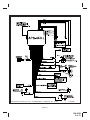
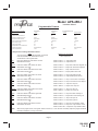
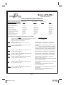
Model APS-45HJ
Manual de Instalación
CARACTERÍSTICAS PROGRAMABLES
Características programables
Selecciones por los interruptores del transmisor
Presione el botón 1
Presione el botón 2
Presione el botón 1&2
Indicación por el tono de la sirena
1 chirrido
2 chirridos
1) El Método armando
armado pasivo
armado activo
3 chirridos
armado pasivo
Preajuste
2) Ignición cerradura automática
& Ignición cerradura abierta automática
no operacional
operacional
no operacional
3) Bloqueos de puerta
cerrado activo
cerrado pasivos
cerrado activo
4) Pulso solo o doble abre
solo pulso abre
pulso doble abre
solo pulso abre
5) Cerradura y cerradura abierta
1 segunda duración
3 segunda duración
1 segundo duracion
6) Chirridos de la sirena de arm/disarm
operacional
no operacional
operacional
7) Chirridos de la bocina de arm/disarm
operacional
no operacional
operacional
8) El rearmado automático
operacional
no operacional
operacional
9) Característica antisecuestro/antiasalto
no operacional
operacional
10) Duracion del chirrido de bocina
10ms
16ms
Para programar las siguientes características seleccionables:
Acción
Encienda el mecanismo de encendido entonces apague el mismo
Presione y suelte el interruptor del valet 6 veces
Dentro de un plazo de 15 segundos
Primero
Presione y suelte el interruptor del valet una vez.
El LED centelleo una vez
o
Segundo Presione y suelte el interruptor del valet dos veces.
El LED centelleo dos veces
Tercero
Cuarto
Quinto
o
Presione y suelte el interruptor del valet tres veces.
El LED centelleo tres veces
o
Presione y suelte el interruptor del valet cuatro veces
El LED centelleo cuatro veces
o
Presione y suelte el interruptor del valet cinco veces
cerradura El LED centelleo cinco veces
Sexto
o
Presione y suelte el interruptor del valet seis veces
El LED centelleo seis veces
Séptimo
o
Presione y suelte el interruptor del valet siete veces
El LED centelleo seis veces
no operacional
30ms
16ms
Respuesta del sistema
Ninguna respuesta
1 chirrido
Presione el botón 1 del transmisor = Armado pasivo
Presione el botón 2 del transmisor = Armado activo
Presione el botón 1 del transmisor = Ignición cerradura
automática & Ignición cerradura abierta no automática
Presione el botón 2 del transmisor = Ignición cerradura
no automática & Ignición cerradura abierta automática
Presione el botón 1 del transmisor = cerradura activo
Presione el botón 2 del transmisor = cerradura pasivo
Presione el botón 1 del transmisor = solo pulso abre
Presione el botón 2 del transmisor = pulso doble abre
Presione el botón 1 del transmisor = Cerradura y
abierta 1 segunda duración
Presione el botón 2 del transmisor = Cerradura y cerradura
abierta 3 segunda duración
Presione el botón 1 del transmisor = De sirena chirridos
de arm/disarm
Presione el botón 2 del transmisor = De sirena no
chirridos de arm/disarm
Presione el botón 1 del transmisor = El bocina chirridos
de arm/disarm
Presione el botón 2 del transmisor = El bocina no
chirridos de arm/disarm
Página 1
Released: 4-23-04
128-8820
1 of 12
Octavo
o
Presione y suelte el interruptor del valet ocho veces
El LED centelleo ocho veces
Noveno
o
Presione y suelte el interruptor del valet nueve veces
El LED centelleo nueve veces
Diez
o
Presione y suelte el interruptor del valet diez veces
El LED centelleo nueve veces
Presione el botón 1 del transmisor = El rearming
automático funciona
Presione el botón 2 del transmisor = El rearming
automático no funciona
Presione el botón 1 del transmisor = Antisecuestro mode
no funciona
Presione el botón 2 del transmisor = Antisecuestro mode
funciona
Presione el botón 1 del transmisor = Duración del chirrido
10mS
Presione el botón 2 del transmisor = Duración del chirrido
16mS
Presione ambos botón del transmisor juntos = Duración
del chirrido 30mS
NOTA: Si se gira la ignición, o si expiran 15 segundos sin ninguna actividad, el modo de programa será terminado, indicado por 3
chirridos de la sirena.
INSTALACIÓN DE LOS COMPONENTES PRINCIPALES
Módulo de control:
Seleccione un lugar de montaje dentro del compartimiento de pasajeros (detrás del tablero de instrumentos), y
sujételo usando los dos tornillos provistos. El módulo de control también puede sujetarse en posición con amarres
de cable.
No monte el módulo de control en el compartimiento del motor, ya que no es impermeable. También debe evitar el
montaje de la unidad directamente sobre componentes electrónicos instalados en fábrica. Estos componentes podrán
ocasionar interferencia RF, lo que puede conducir en deficiencias del alcance del transmisor u operación intermitente.
Sirena:
Seleccione un lugar de montaje en el compartimiento del motor bien protegido contra acceso desde debajo del
vehículo. Evite las áreas cerca de componentes de mucho calor o las piezas móviles dentro del compartimiento del
motor. Para evitar la retención de agua, el extremo abocinado de la sirena ya montada debe apuntar hacia abajo.
Monte la sirena en el lugar seleccionado usando los tornillos y la ménsula provistos.
NOTA: La selección del tono está alcanzada a través del enchufe de goma situado en la parte posterior de la sirena.
Cambie 1 tono 1 de los controles, el tono 2 de los controles del interruptor 2, el etc... Tome el cuidado para no perder
el enchufe de goma pues esto permitirá que el agua dañe la electrónica y la garantía vacía.
Conmutador de clavija del capó o baúl:
Se incluye un conmutador de clavija para la protección del capó o baúl (o puerta trasera) del vehículo. El conmutador
siempre debe montarse en una superficie metálica puesta a tierra del vehículo. Es importante seleccionar un lugar
donde no pueda fluir ni acumularse agua, y evitar las canaletas de goteo en las paredes de parachoques del capó y el
baúl. Seleccione lugares protegidos por empaquetaduras de goma cuando el capó o baúl está cerrado.
El conmutador de clavija puede montarse usando la ménsula provista, o montarse directamente, taladrando un agujero
de montaje de ¼” de diámetro. Tenga presente que, una vez montado correctamente, el émbolo del conmutador de
clavija debe deprimirse por lo menos ¼” cuando se cierra el capó o la tapa del baúl.
Indicador LED montado en el tablero de instrumentos:
Se incluye un pequeño indicador LED rojo que servirá de indicador visual de la situación de alarma. El indicador LED
debe instalarse en el tablero de instrumentos, en un lugar donde sea fácilmente visible desde el exterior del vehículo,
pero que no constituya una distracción para el chofer.
Una vez seleccionado el lugar, inspeccione detrás del panel para averiguar el acceso a la vía de cables y para
confirmar que el taladro no dañará ningún componente existente al atravesar el panel.
Taladre un agujero de ¼” de diámetro y pase los cables rojo y azul del indicador LED a través del agujero, desde el
frente del panel. Presione firmemente el cuerpo del indicador LED dentro del agujero hasta que haya quedado
plenamente asentado.
Conmutador de anulación/habilitación de la manera antisecuestro, manteniendo, e invalidación:
Seleccione un lugar oculto para este conmutador, al alcance del chofer del vehículo. Este conmutador puede montarse
detrás de un panel blando del tablero de instrumentos, por arriba del chofer debajo del forro de techo o debajo del
asiento del chofer. Este conmutador debe quedar al alcance del operador del vehículo. Los lugares mencionados no
están visibles y sólo serán conocidos por el operador del vehículo, pero permiten la activación del conmutador
cuando sea necesario para mantener o la invalidación del modo antisecuestros.
Página 2
128-8820
2 of 12
Detector de choques de doble etapa
Seleccione una superficie de montaje sólido para el detector de choques en la pared contrallamas dentro del
compartimiento de pasajeros y monte el detector con los dos tornillos provistos. El detector de choques también
puede sujetarse a cualquier elemento fijo detrás del tablero de instrumentos usando amarres de cable.
Cualquiera que sea el método de montaje seleccionado, cerciórese de que haya acceso al ajuste de sensibilidad
para uso más adelante en la instalación. Cable el detector de acuerdo con la guía de instalación incluida con el
detector o mostrado más adelante en este manual.
ALAMBRADO DEL SISTEMA
Cable fusible rojo: FUENTE DE PILA CONSTANTE DE +12 VCC
Este cable suministra energía al módulo de control. Conecte con la fuente de la batería de +12 constantes con
mínimo la fuente de 15 amperios.
Cable anaranjado: SALIDA A TIERRA DE 300 mA AL ESTAR ARMADO - DESHABILITACIÓN DE ENCENDIDO N.C. (Se
requiere relé opcional)
Este cable se proporciona para controlar el relé interruptor de encendido. Conecte el cable anaranjado al terminal de
relé 86. Conecte el terminal de relé 85 a un cable de encendido en el vehículo que tiene corriente cuando la llave se
encuentra en las posiciones encendida y de arranque y está apagado cuando la llave se encuentra en la posición
apagada. (Aquí es donde debe conectarse el cable amarillo de la alarma).
Corte el cable de solenoide de encendido de baja corriente en el vehículo y conecte un lado del cable cortado al
terminal de relé 87A. Conecte el otro lado del cable cortado al terminal de relé 30.
NOTA: Esta configuración da un interruptor de encendido normalmente cerrado, y cuando se quita energía del
sistema de seguridad, la característica de desactivación del encendido no funcionará, permitiendo que
se encienda el vehículo. Audiovox no recomienda usar el cable anaranjado para interrumpir nada más
que el circuito de encendido del vehículo.
Cable blanco: SALIDA PULSADA DE LUZ DE ESTACIONAMIENTO DE +12 VCC (15 AMP MÁX)
Este cable se proporciona para hacer parpadear las luces de estacionamiento del vehículo. Conecte el cable blanco
al lado positivo de una de las luces de estacionamiento del vehículo.
Cable rojo/blanco: SUMINISTRO DE CIRCUITO DE +12 VCC
Véase las instrucciones para el cable rojo arriba. La conexión del cable rojo de arriba completa la conexión para
el cable rojo/blanco.
Cable blanco con raya negra: SALIDA POSITIVA A LA SIRENA
Tienda este cable a través de un ojal de goma en la pared contrallamas hasta el lugar de la sirena. Conecte el cable
blanco/negro al cable positivo, rojo de la sirena.. Sujete el cable de puesta a tierra negro de la sirena a la puesta a tierra
del chasis.
Cable negro: PUESTA A TIERRA DEL CHASIS
Conecte este cable a una pieza metálica sólida del chasis del vehículo. No confunda este cable con el cable negro
delgado de la antena que sale independientemente del módulo de control.
Cable azul oscuro: SALIDA PULSADA DEMORADA DE 200 mA/CANAL 2
El cable azul oscuro pulsa a tierra a través de un canal RF independiente desde el transmisor de llavero. Esta salida es
transistorizada de corriente baja y sólo debe usarse para impulsar una bobina de relé externa.
ADVERTENCIA: La conexión del cable azul oscuro a la salida conmutada de corriente alta de los circuitos de
desenganche de baúl y algunas entradas de activación de encendido remotas dañará el módulo de control.
En estos casos, conecte el cable azul oscuro al terminal 86 del relé AS-9256 (o relé automotor de 30 A equivalente), y
cable los demás contactos de relé para realizar la función seleccionada del canal 2.
Cable Negro con blanco: 200 MA Salida de Vocina / Claxon / Pito
Cable negro con blanco se proporciona para emitir una señal sonora de la bocina del vehículo.
Ésta es una salida de baja corriente y sólo debe ser conectaado al cable de activación de baja corriente negativa
de la vocina del vehículo.
Si el vehículo usa +12 voltios para operar la vocina, un relay optativo debe usarse.
Para esta aplicación, conecte el cable blanco negro a término 86 del 30 amperio reley optativo.
Conecte términal 85 del reley optativo al + 12 voltio fundió fuente de la batería.
Conecte términal 87 de el relay optativa a la salida del interuptor de la vocina del vehiculo.
Conecte términal 30 de el relay optativo al + 12 voltio fundió fuente de la batería.
Cable verde oscuro: Activador instantáneo (-) zona 2
Este cable es un cable de tierra de encendido instantáneo. Debe conectarse a los conmutadores de capó y baúl
instalados anteriormente.
Cable marrón: ACTIVADOR (-) DE PUERTAS
Si los conmutadores de las luces de cortesía del vehículo tienen una salida a tierra (-) al abrirse la puerta (GM y la
mayoría de los modelos importados), usted debe conectar este cable a la salida negativa de uno de los conmutadores
de puerta.
ADVERTENCIA: No use el cable marrón si el vehículo tiene conmutadores de puerta de salida de +12 voltios
(véase Cable violeta).
Página 3
128-8820
3 of 12
Cable violeta: ACTIVADOR (+) DE PUERTAS
Si los conmutadores de las luces de cortesía de las puertas del vehículo tienen una salida de +12 voltios al abrirse
la puerta (la mayoría de los modelos Ford y algunos importados), usted debe conectar este cable a la salida positiva
de uno de los conmutadores de puerta. En la mayoría de los casos, el cable malva sólo tendrá que conectarse a un
conmutador de puerta, sin importar el número de puertas que tenga el vehículo.
ADVERTENCIA: No use el cable malva si el vehículo tiene conmutadores de puerta de tipo salida de tierra.
(véase Cable marrón).
Cable amarillo: FUENTE DE ENCENDIDO DE +12 VCC
Conecte este cable a una fuente con corriente cuando la llave está en las posiciones encendida y de arranque. Cerciórese
de que esta fuente esté apagada cuando la llave se encuentra en la posición apagada.
Conector blanco de 2 clavijas: INDICADOR LED MONTADO EN EL TABLERO DE INSTRUMENTOS
Tienda los cables rojo y azul en el conector blanco de 2 clavijas del indicador LED hasta el módulo de control y enchufe
el conector en el conector blanco correspondiente en el lado del módulo.
Conector rojo de 2 clavijas: ANULACIÓN DE MODO ANTISECUESTRO MANTENIENDO, e INVALIDACION
Tienda el conector rojo del conmutador de anulación montado anteriormente al conector de dos clavijas
correspondiente en el módulo.
Conector de 4 clavijas: roja, negra, verde y azul. Detector de choque
Este conector blanco de 4 clavijas se usa para conectar el detector de choque previamente instalado. Encamine los
4 cables, del detector al conector correspondiente del sistema de alarma.
Bloqueos de puerta conmutados a tierra de 3 cables
En esta aplicación, el cable rojo proporciona un impulso a tierra durante el armado, o la salida pulsada de bloqueo a
tierra. Conecte el cable rojo al cable que proporciona una señal de tierra de corriente baja desde el conmutador de
bloqueo de puertas de fábrica hasta el relé de control de bloqueo de fábrica.
El cable verde proporciona un impulso a tierra durante el desarmado, o la salida pulsada de desbloqueo a tierra.
Conecte el cable verde al cable que proporciona una señal de tierra de corriente baja desde el conmutador de desbloqueo
de puertas de fábrica hasta el relé de control de bloqueo de puertas de fábrica.
Circuitos de control de bloqueo de puertas de:
Bloqueos de puerta conmutados positivos de 3 cables
Inversión de polarización y
12 voltios alternos de 5 cables
En estas aplicaciones, debe usarse la Interconexión de Bloqueo de Puertas AS 9159 (o relés automotores de 30 A
equivalentes). Refiérase al Suplemento de Alambrado de Bloqueo de puertas de AUDIOVOX para la conexión apropiada
a estos tipos de circuitos.
TERMINACIÓN DE LA INSTALACIÓN
Cable de antena: Cerciórese de extender el cable negro delgado de la antena su largo completo y de sujetarlo en
posición con amarres de cable donde no puede dañarse. Evite envolver este cable alrededor de bobinas de cables
grandes de corriente alta.
Ajuste del detector de choques:
Ajuste el accordung del sensor del choque a la talla del vehículo. Considere la causa demasiado sensible de la voluntad
las activaciones falsas, y demasiado insensible no protegerá el vehilce. Ajuste por consiguiente.
Terminado de cables: Siempre envuelva los cables de la alarma en un tubo en espiral, o con una envoltura helicoidal de
cinta eléctrica. Sujete estos grupos a lo largo de la vía de cables usando amarres de cable. De esta manera se asegurará
que los cables de la alarma no se dañen por haber caído sobre superficies calientes o móviles en el vehículo.
Operación: Tome unos momentos para marcar las casillas de opciones apropiadas en el manual del propietario y
explicar plenamente la operación del sistema a su cliente.
INFORMACIÓN DE PROGRAMACIÓN ADICIONAL
El receptor del modelo APS-45HJ funciona como sigue. El canal receptor 1 opera la alarma/armado así como la
característica de emergencia del sistema.
El canal receptor 2 opera la alarma desarmado/desbloqueo así como la característica de emergencia del
sistema.
El canal receptor 3 opera el cable de salida del canal tres (azul oscuro)
El canal receptor 4, se puede utilizar para activar una opción o una segunda alarma de Audiovox que presiona
ambos el & de la cerradura; Abra los botones mientras que es la ignición encendido activará el modo anti del
secuestro cuando la característica se selecciona encendido.
NOTA: La característica #9 del módulo debe ser seleccionada en. Sírvase consultar la información de
programación del transmisor contenida en la manual del propietario.
Página 4
128-8820
4 of 12
© 2010 Audiovox Electronics Corp., 150 Marcus Blvd., Hauppauge, N.Y. 11788
128-8820
Página 5
128-8820
5 of 12
Esta página izquierda vacia intencionalmente
Página 5
128-8820
6 of 12
Model APS-45HJ
Installation Manual
Programmable Features
Select By Operating Transmitter
Press Button 1
Press Button 2
Press Both Buttons1&2
Siren Indications
1 Chirp
2 Chirps
3 Chirps
1) Arming Method
Passive Arm
Active Arm
Factory Default
Passive Arm
2) Ignition Control Lock/Unlock
Off
On
Off
3) Passive Or Active Door Locks
Active
Passive
Active
4) Single Or Double Pulse U/L
Single Pulse
Double Pulse
Single
5) Door Lock/Unlock Pulse Duration
1 Second
3 Seconds
1 Second
6) Siren Chirps On/Off
On
Off
On
7) Horn Chirps On/Off
On
Off
On
8) Passive Rearm From Active State
On
Off
On
9) Anti Hi-Jack Feature
Non Operational
Operational
Non Operational
10) Horn Chirp Duration
10ms
16ms
To Program The Following Selectable Features:
Action
Turn The Ignition On Then Off And Within 10 Seconds
Press And Release The Valet Switch 6 Times
You Are Now In The Program Mode
First
Second
Third
Fourth
Fifth
Sixth
Seventh
Eighth
Ninth
Tenth
NOTE:
Press and release the valet switch one time
LED Flashes One Time
or
Press and release valet switch two times
LED Flashes Two Times
or
Press and release valet switch three times
LED Flashes Three Times
or
Press and release valet switch four times
LED Flashes Four Times
or
Press and release valet switch five times
LED Flashes Five Times
or
Press and release valet switch six times
LED Flashes Six Times
or
Press and release valet switch seven times
LED Flashes Seven Times
or
Press and release valet switch eight times
LED Flashes Eight Times
or
Press and release valet switch nine times
LED Flashes Nine Times
or
Press and release valet switch ten times
LED Flashes Ten Times
30ms
16ms
Response Of The System
No Response
Siren Chirps Once
Press tx button 1 = 1 chirp passive arm
Press tx button 2 = 2 chirps active arm
Press tx button 1 = 1 chirp auto lock/unlock w/ignition off
Press tx button 2 = 2 chirps auto lock/unlock w/ignition
Press tx button 1 = 1 chirp active door locks
Press tx button 2 = 2 chirps passive door locks
Press tx button 1 = 1 chirp single pulse unlocks
Press tx button 2 = 2 chirps double pulse unlocks
Press tx button 1 = 1 chirp 1 second door L/UL Output
Press tx button 2 = 2 chirps 3 second door L/UL Output
Press tx button 1 = 1 chirp siren chirps on
Press tx button 2 = 2 chirps siren chirps off
Press tx button 1 = 1 chirp horn chirps on
Press tx button 2 = 2 chirps horn chirps off
Press tx button 1 = 1 chirp active auto rearming on
Press tx button 2 = 2 chirps active auto rearming off
Press tx button 1 = 1 chirp anti hi-jack off
Press tx button 2 = 2 chirps anti hi-jack on
Press tx button 1 = 1 chirp horn chirp duration 10mS
Press tx button 2 = 2 chirps horn chirp duration 16 mS
Press tx button 1&2 = 3 chirpshorn chirp duration 30mS
While in the program mode, if the ignition switch is turned on, or if 15 seconds of inactivity expire the program mode will
terminate, indicated by 3 chirps of the siren.
Page 7
128-8820
7 of 12
INSTALLATION OF THE MAIN COMPONENTS
Control Module :
Select a mounting location inside the passenger compartment (up behind the dash), and secure using the two
screws provided. The control module can also be secured in place using cable ties.
Do not mount the control module in the engine compartment, as it is not waterproof. You should also avoid mounting
the unit directly onto factory installed electronic components. These components may cause RF interference, which can
result in poor transmitter range or intermittent operation.
Siren:
Select a mounting location in the engine compartment that is well protected from access below the vehicle. Avoid
areas near high heat components or moving parts within the engine compartment. To prevent water retention, the
flared end of the siren must be pointed downward when mounted.
Mount the siren to the selected location using the screws and bracket provided.
NOTE: The siren used with this kit has selectable tones controlled by dip switch located inside the rubber cover
mounted on the rear of the siren. On/Off of tone 1 is controlled by switch 1, on/off of tone 2 is controlled by switch 2,
etc,,,. Be careful not to lose the rubber cover as loss of this will allow water to get into the siren causing electronic
damage and voiding warranty.
Hood or Trunk Pin Switch:
A pin switch is included for use in protecting the hood or trunk (or hatchback) of the vehicle. The switch must always
be mounted to a grounded, metal surface of the vehicle. It is important to select a location where water cannot flow or
collect, and to avoid all drip gutters on hood and trunk fender walls. Choose locations that are protected by rubber
gaskets when the hood or trunk lid is closed.
The pin switch can be mounted using the bracket provided, or direct mounted by drilling a ¼ “ diameter mounting hole.
Keep in mind that when properly mounted, the plunger of the pin switch should depress at least ¼ “ when the hood or
trunk lid is closed.
Dash Mounted LED:
A small red LED is included that will serve as a visual indicator of the alarm status. It should be installed in the dash,
located where it can be easily seen from outside the vehicle, yet not be distracting to the driver.
Once a location has been selected, check behind the panel for wire routing access, and to confirm the drill will not
damage any existing components as it passes through the panel.
Drill a ¼ “ diameter hole, and pass the red and blue wires from the LED through the hole, from the front of the panel.
Firmly press the body of the LED into the hole until fully seated.
Valet/Programming/Hi-Jack Override Switch:
Select a covert location for this switch within reach of the driver of the vehicle. This switch can be mounted behind a soft
dash panel, above the driver under the headliner, under the driver's seat. This switch must be within reach of the
operator of the vehicle. The locations mentioned are hidden from view and will be known only to the vehicle operator yet
they allow activation of the switch when necessary.
Two Stage Shock Sensor:
Select a solid mounting surface for the shock sensor on the firewall inside the passenger compartment, and mount
the sensor using the two screws provided. The shock sensor can also be secured to any fixed brace behind the dash
using tie straps.
Whichever mounting method is selected, make certain that the sensitivity adjustment is accessible for use later in the
installation. Wire thesensor as per the instructions packaged with the unit or shown later in this manual.
WIRING THE SYSTEM
Red Fused Wire: + 12 VDC CONSTANT BATTERY SOURCE
This wire supplies power to the control module’s Red/White wire, and supplies power to the on-board parking light
relay.
This wire must connect to a circuit that is capable of supplying more than 15 Amps as dictated by the parking light
circuit.
Orange Wire: 300 mA GROUND OUTPUT WHEN ARMED - N. C. STARTER DISABLE
This wire is provided to control the starter cut relay. Connect the orange wire to terminal 86 of the relay. Connect relay
Page8
128-8820
8 of 12
terminal 85 to an ignition wire in the vehicle that is live when the key is in the on and crank positions, and off when the
key is in the off position. ( This is where the yellow wire from the alarm should be connected ).
Cut the low current starter solenoid wire in the vehicle, and connect one side of the cut wire to relay terminal 87A.
Connect the other side of the cut wire to relay terminal 30.
NOTE: This is a normally closed starter cut arrangement, and when power is removed from the security system,
the starter disable feature will not operate, allowing the vehicle to start. Audiovox does not recommend
using the Orange wire to interrupt anything but the starting circuit of the vehicle.
White Wire: + 12 VDC PULSED PARKING LIGHT OUTPUT (15 AMP MAX)
This wire is provided to flash the vehicle’s parking lights. Connect the white wire to the positive side of one of the
vehicle’s parking lights.
Red/White Wire: + 12 VDC CIRCUIT SUPPLY
See Red Wire above. Connecting the above Red wire completes the connection for the Red/White wire.
White w/ Black Trace Wire: POSITIVE OUTPUT TO SIREN
Route this wire through a rubber grommet in the firewall, and to the siren location.
Connect the white / black wire to the positive wire of the siren. Secure the black ground wire of the siren to chassis
ground.
Black Wire: CHASSIS GROUND
Connect this wire to a solid, metal part of the vehicle’s chassis. Do not confuse this wire with the thin black antenna
wire that exits the control module independently.
Dark Blue Wire: DELAYED 200 mA PULSED OUTPUT / CHANNEL 2
The dark blue wire pulses to ground via an independent RF channel from the keychain transmitter. This is a transistorized, low current output, and should only be used to drive an external relay coil.
WARNING: Connecting the dark blue wire to the high current switched output of trunk release circuits, and some remote
start trigger inputs, will damage the control module.
In these cases connect the dark blue wire to terminal 86 of the AS-9256 relay (or equivalent 30 A automotive relay), and
wire the remaining relay contacts to perform the selected function of channel 2.
Black w/ White Trace Wire: 200 mA Horn Output
The black w/ white trace wire is provided to beep the vehicle’s horn. This is a transistorized low current output, and
should only be connected to the low current ground output from the vehicle’s horn switch.
If the vehicle uses a + 12 VDC horn switch, then connect the black w/ white trace wire to terminal 86 of the AS-9256 relay
(or an equivalent 30 Amp automotive relay), and connect relay terminal 85 to a fused + 12 VDC battery source. Connect
relay terminal 87 to the vehicle’s horn switch output, and connect relay terminal 30 to a fused + 12 VDC battery source.
Dark Green Wire: ( - ) Instant Trigger Zone 2
This is an instant on ground trigger wire. It must be connected to the previously installed hood and trunk pin switches.
Brown Wire: - DOOR TRIGGER
If the vehicle’s courtesy light switches have a ( - ) ground output when the door is opened (GM and most Imports), you
must connect this wire to the negative output from one of the door switches.
WARNING:
Do not use the brown wire if the vehicle has + 12 volt output type door switches. (see Purple Wire).
Purple Wire: + DOOR TRIGGER
If the vehicle’s door courtesy light switches have a + 12 volt output when the door is opened (most Fords and some
Imports), you must connect this wire to the positive output from one of the door switches. In most cases, the purple wire
will only needs to be connected to one door switch, no matter how many doors the vehicle has.
WARNING: Do not use the purple wire if the vehicle has ground output type door switches. (see Brown Wire).
Yellow Wire: + 12 VDC IGNITION SOURCE
Connect this wire to a source that is live when the key is in the on and crank positions. Be sure that this source is off
when the key is in the off position.
2 Pin White Connector: DASH MOUNTED LED
Route the red and blue wires in the 2 pin white connector from the LED to the control module, and plug it into the mating
white connector on the side of the module.
2 Pin Red Connector: VALET/PROGRAMMING/HI-JACK OVERRIDE SWITCH
Route the 2 pin red connector from the override switch previously mounted to the mating two pin connector on the
module.
4 Pin White Connector: red, black, green & blue. Shock Detector Harness
Route the 4 pin connector form the previously installed shock sensor to the mating 4 pin connecotr of the module.
Page 9
128-8820
9 of 12
Red & Green 2 Pin White Connector: DOOR LOCK OUTPUTS
These wires will provide a pulsed ground output to the factory door lock control relay. The maximum current draw
through these outputs must not exceed 300 mA.
3 Wire Ground Switched Door Locks
In this application, the red wire provides a ground pulse during arming, or the pulsed ground lock output. Connect the
red wire to the wire that provides a low current ground signal from the factory door lock switch to the factory door lock
control relay.
The green wire provides a ground pulse during disarming, or the pulsed ground unlock output. Connect the green
wire to the wire that provides a low current ground signal from the factory door unlock switch to the factory door lock
control relay.
3 Wire Positive Switched Door Locks
4 Wire Polarity Reversal and
5 Wire Alternating 12 Volt
Door Lock Control Circuits
In these applications, the AS 9159 Door Lock Interface (or equivalent 30 A automotive relays) must be used. Refer to the
AUDIOVOX Door Lock Wiring Supplement for proper connection to these types of circuits.
COMPLETING THE INSTALLATION
Antenna Wire : Be sure to extend the thin black antenna wire to it’s full length, and cable tie into place where it cannot
be damaged. Avoid wrapping this wire around major, high current wire looms.
Adjusting the Shock Sensor: If used, the sensitivity of the pre-detect circuit is automatically set 30% less sensitive than
the full trigger circuit.
Using a small screwdriver, gently turn the adjustment screw fully counterclockwise. (DO NOT over turn this screw.
Maximum rotation for this adjustment is 270°). Close the hood and trunk lids, and arm the alarm. Wait 6 seconds for the
accessories trigger zone to stabilize, then firmly strike the rear bumper with the side of a closed fist considering the
amount of force required to break a window.
CAUTION: Never perform this test on the vehicle’s glass, as you may break the window.
Turn the adjustment screw clockwise (increasing sensitivity) about ¼ turn and re - test. Repeat this procedure until the
alarm sounds. Ultimately, one firm strike to the rear bumper will cause the alarm to emit pre - detect warning tones.
WARNING ! Setting the sensitivity too high can cause false alarms due to noise vibrations from passing trucks and
heavy equipment. To decrease sensitivity, turn the adjustment screw counter clockwise.
Wire Dressing: Always wrap the alarm wires in convoluted tubing, or with a spiral wrap of electrical tape. Secure these
looms along the routing using cable ties. This will ensure that the alarm wires are not damaged by falling onto hot or
sharp moving surfaces in the vehicle.
Operation: Take a few moments to check off the appropriate option boxes in the owner’s manual, and to fully explain the
operation of the system to your customer.
ADDITIONAL INFORMATION:
The APS-45HJ comes programmed with button 1, controlling Arm/Lock and panic.
Button 2 controlling Disarm/Unlock and panic.
Button 3 operates the channel 3 output’s Dark Blue wire.
Button 4 , can be used to activate an option or a second Audiovox Alarm Pressing both the Lock & Unlock buttons while the ignition
is on will activate the Anti Hijack mode when the feature is selected on.
NOTE: The Hijack feature #9 of the module must be selected on to take advantage of this feature. For information consult the
feature programming section of this manual. For transmitter programming information, consult the owners manual under the title
transmitter programming.
Page10
128-8820
10 of 12
Page 11
128-8820
11 of 12
This Page Intentionally Left Blank
© 2010 Audiovox Electronics Corp., 150 Marcus Blvd., Hauppauge, N.Y. 11788
128-8820
Page 12
128-8820
12 of 12