1
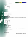
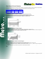
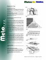
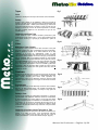
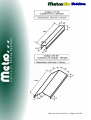
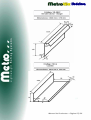
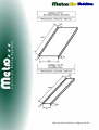
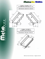
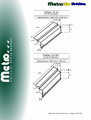
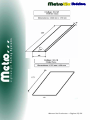
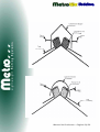
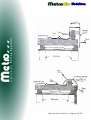
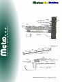
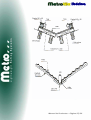
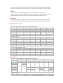
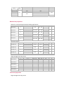
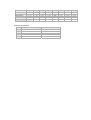
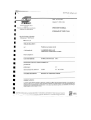
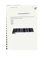
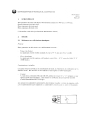
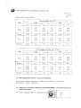
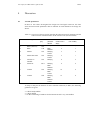
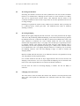
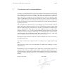
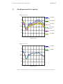
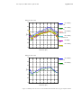
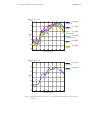
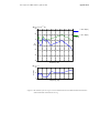
MANUAL
DE
PRODUCTOS
Rua do Calvário, 123 – Apartado 48 – 4905-909 BARROSELAS
PORTUGAL
+351 258 770 360
+ 351 258 770 369
! [email protected]
www.metrotile.com.pt
EL
PRODUCTO…
Manual de Productos – Pagina 2/39
El sistema de cubiertas METROTILE tuve su origen en
Nueva Zelanda en 1946. En esto momento es vendido en
todo el Mundo e tiene fábricas en Nueva Zelanda, EE.UU.
e Bélgica.
Sus principales ventajas:
Tejas grandes (solo 2 tejas/m2)
Muy fácil instalación;
Costes muy bajos de montaje;
Costes muy bajos de almacenaje y transporte;
Liviana (pesa solo 7 Kg./m2);
Muy agradable estéticamente;
Ruido de la lluvia igual a la teja cerámica;
Resistencia al viento (resiste a 200 Km./h);
Sin costes de manutención;
Bueno aislamiento térmico e acústico;
Disponible en 6 colores Standard;
Manual de Productos – Pagina 3/39
Permite pendientes mínimos de 10º;
Permite caminar por arriba;
Resistente al fuego – Índice A;
Resistente a la proximidad del mar;
Resistente a choques térmicos;
Vasta gama de accesorios;
Garantía 30 años;
Producto Certificado ISO 9001:2000
Manual de Productos – Pagina 4/39
Manual de Productos – Pagina 5/39
EL
SERVICIO…
Manual de Productos – Pagina 6/39
Además de tener un excelente producto, METROTILE se
distingue por un servicio pensando en el cliente, do cual
destacamos el siguiente:
Entregas muy rápidas – de 2 a 8 días
laborables. (tenemos un stock permanente de
más de 200.000 m2 de teja)
Hacemos accesorios a la medida del cliente; (*)
Podemos hacer cualquier color al gusto del
cliente; (*)
Desarrollo continuo de nuevos productos,
presentando
normalmente
entre
2
a
3
productos nuevos por año.
Busca contínua de soluciones de cubierta
mejores, más bonitas y más rápidas de colocar.
(*) – Dependiendo de las cantidades del pedido.
Manual de Productos – Pagina 7/39
Instrucciones
de Montaje
Manual de Productos – Pagina 8/39
Equipamiento para la Instalación
Cizalla
Para fácil transporte, las piernas salen. La lamina es hecha en acero de mola
Superficie Ocupada: 3700mm x 1000mm
Largo: 1100mm
Peso: 29Kg
Accesorios para doblar la teja
El dibujo muestra la dobladora con el accesorio para las tejas, en la posición correcta. Está fijado á la dobladora con tornillos de
12.5mm e puercas de orejas.
Largo
:
1600mm
Peso
:
26 Kg
Dobladora
Superficie ocupada:
Anchura
:
Peso:
:
490mm x 460mm
530mm
25 Kg
Vara de Medición (echa en el local)
Echo en madera, con 50x25 mm ó 50x40 mm de sección e 3m a 5m de largo, con marcas de intervalos exactos de 370 mm. En
alternativa a la madera, la vara podrá ser de aluminio y pode ser echa por el instalador.
Otro Equipamiento de Instalación Necesario
Tijeras de Chapa
Martillo
Cinta Métrica
Hilo de marcación ó Línea de tiza
Tiza (para marcar las tejas)
Zapatos de borracha macia
Manual de Productos – Pagina 9/39
Embalaje
Las tejas son colocadas en paletas de madera, con las dimensiones a seguir indicadas.
Producto
Por paleta
Peso máximo
Tamaño
Volumen (m3)
MetroBond
MetroShake
350
350
1085 Kg
1085 Kg
1.4 x1.1 x 0.9
1.4 x1.1 x 0.9
1.38 m3
1.38 m3
MetroBond
MetroShake
Peso por Teja
3.1 Kg
3.1 Kg
Peso / m2
6.66 Kg m2
6.66 Kg m2
Camión Completo: 18 paletas de teja más el suficiente numero de accesorios pueden ser embalados en un contenedor
normalizado de 20’. Esta cantidad permite una cobertura de aproximadamente 3000 m2. A pedido, se puede utilizar un embalaje
especial para satisfacer exigencias específicas.
Almacenamiento
Para almacenamiento exterior, se debe providenciar una cobertura de protección para mantener los productos secos e prevenir
estropeos.
Movimientación
Para evitar estropeos de la superficie, debe ser tomado alguno cuidado en la movimientación de las tejas. En el caso de
pequeños estropeos debe ser usado el kit de reparación.
Manual de Productos – Pagina 10/39
Dados Para los Cálculos Estimativos
Cuando se hace la estimativa del número de tejas necesarias, se debe utilizar la tabla que indica los factores a usar para dividir
la anchura e el largo del tejado, para calcular el número de líneas de teja e el número de tejas por línea.
Anchura de la
Teja [m]
Largo de la Teja
[m]
MetroBond
MetroShake
MetroShingle
0.37
0.37
0.24
1.25
1.25
1.25
1) Estimativa de Tejas para un Tejado de 2 aguas
(a) Determine la anchura del tejado (Fig.1) e divida-o por el factor de la teja que va a usar;
(b) Determine la longitud total del tejado (Fig.1), e divida-a por el factor de teja que va a usar;
(c) Multiplique (a) por (b), asegurando que las tejas fraccionadas son contadas como tejas completas;
(d) Para calcular el total de ambos los lados del tejado, multiplique lo resultado por dos.
Fig.1
2) Estimativa de Tejas para un Tejado de 4 aguas
(a) De inicio, se considera el tejado como un tejado de 2 aguas e calcule como en 1 (a),(b),(c) y (d);
(b) Determine la longitud de la cumbrera (Fig.2) y, usando una de las fórmulas referidas en 4, calcule el número de tejas extra
que necesita. Suma este número a las tejas necesarias para el tejado.
Fig.2
3) Estimativa de Tejas para Tejados con más de 4 Aguas
(a) Determine las tejas necesarias para las secciones (a), (b) y (c) da Fig.3 e calcule como en 1(a), (b) y (c)
(b) Adicione los totales de (a), (b) y (c) e multiplique por dos, para los dos lados.
(c) Determine la dimensión total de las cumbreras y vales, usando la fórmula referida en 4, calcule el número de tejas extra
necesarias;
(d) Adicione este total al total calculado antes para obtener el total de tejas necesarias.
Fig.3
Manual de Productos – Pagina 11/39
4) Estimativa de Tejas Adicionales
La cantidad de tejas adicionales para cumbreras e vales pueden ser estimadas usando la siguiente fórmula:
Tejas adicionales = Total de las cumbreras y vales en metros lineares x 0,6 (factor de desperdicio) x 2,15 (tejas por metro
cuadrado).
5) Estimativa de Accesorios
Cuando se hace el cálculo de los accesorios necesarios, se debe incluir algunos más para compensar pierdas.
(a) LINEA DE CUMBRERA: Determine la longitud de la cumbrera e divida por la cobertura linear por cumbrera, para calcular el
numero de unidades necesarias;
(b) REMATES LATERALES: Determine la anchura del tejado e divida por la cobertura linear de cada remate lateral para
calcular el numero de unidades necesarias;
6) Estimativa de Rasteles para Nueva Cubierta
Se necesita de 3ml de rasteles por metro cuadrado de tejado.
7) Estimativa de Vigas para Reforma de Tejados
Se necesita de 5 ml de rasteles por metro cuadrado de área de tejado.
8) Métodos Simplificados para Estimativa Rápida
Indicamos abajo algunos métodos para estimativa rápida de cantidades necesarias.
a) TEJADOS CON 4 Ó MÀS AGUAS: calcular igual a tejados de 2 aguas, e adicionar media teja por línea para cada cumbrera ó
vale para compensar desperdicios;
(b) REMATE LATERAL (excepto remate en cascada): una pieza por cada tres líneas de tejas:
(c) RASTELES: El numero de tejas más 50% equivalente a los metros lineares de rasteles necesarios;
Manual de Productos – Pagina 12/39
Mediciones e Marcación
con una tiza. Esto forma la línea de corte (Fig.2).
Las mediciones son hechas en el tejado, pero se aconseja
que las tejas sean marcadas, cortadas, dobladas y
apiladas en el suelo.
Para ganar tiempo en la marcación, corte y doblaje de
cada teja, se aconseja que el trabajo sea hecho por dos
instaladores – uno para medir y otro para registrar lo
resultado de las mediciones en el papel. Para evitar
confusiones, corte, doble y apile exactamente por su
orden.
Atención a lo siguiente:
(i)
La medición básica es hecha a partir de la ultima
saliencia del canto inferior de la teja, para el parte
superior, en línea con la arista frontal de la vigota
(Fig.1)
(ii) Mida y marque en las tejas con una tiza, las medidas
quitadas del tejado, asegurando que la unión de la
saliencia de sobre posición de la teja a cortar, es
tomada como la medida del punto de partida (Fig.1).
Esto forma una línea de doblaje (Fig.2).
ALTERNATIVAMENTE – Haga un molde de ángulo formado por la viga de cumbrera y los rasteles del tejado. Ponga
el molde en la teja de modo a que la marca de medición en
la parte frontal de las líneas superiores de la teja se una
con la parte interior del molde. Marque en línea con la
parte inferior de la moldura para definir la línea de doblaje.
Cada teja deberá permitir dos piezas cortadas con un
mínimo de desperdicios (Fig.2)
NOTA: Como las mediciones son hechas en línea con el
canto de la viga, las marcas de las medidas en la teja
deberán ser, también, en conformidad.
Añadir a la medida de la línea de doblaje, la altura de la
proyección arriba de la línea de la teja. Marque en las tejas
Fig.1
Fig.2
Manual de Productos – Pagina 13/39
Productos de Ventilación
Tejas de Ventilación
Las Tejas de Ventilación Metrotile fueran hechas para que no sean visibles en su tejado. Fabricadas en PVC estable a
los rayos Ultra Violeta, estas tejas están disponibles para combinar con todas las colores padrón Metrotile. Indicadas
para su aplicación en una zona de unión, donde las paredes de protección del fuego cortan el espacio del tejado y, aún
cuando sus características de concepción dificultan la ventilación cruzada.
Las tejas de ventilación Metrotile producen 7500 mm2 de corriente de aire por metro linear. Además de hacer una
ventilación efectiva, las Tejas de ventilación Metrotile son extremamente eficaces en la prevención contra la entrada,
para el espacio del tejado, de lluvia, nieve y pájaros.
Tubo de Ventilación
Para una excelente resistencia a la corrosión, los terminales de exhaustión de gases Metrotile (o tubos de ventilación)
son manufacturados en acero galvanizado y tratados de modo a que poda obtener un acabamiento igual a los
padrones de las tejas. Incorporando un filtro protector para evitar la entrada de pájaros, los terminales dan una
resistencia baja a la exhaustión de gases. Además, estos terminales satisfacen todas las reglamentaciones relevantes
de la construcción escocesas (Building Regulations and Scottish Building Standards) y, son propias para las
aplicaciones até 60KW
Manual de Productos – Página 14/39
Montaje de las Tejas
Fig.1
Colocación de las Tejas
Las tejas pueden ser ligadas entre sí tanto por el lado
derecho, como por el izquierdo, pero deben ser
colocadas con la orilla escapando a los vientos
predominantes y de los tubos de descarga de agua o
del canelón.
Cuando sea posible, las tejas deben ser colocadas con
las orillas a partir del lado normal.
Las tejas son colocadas levantando simultáneamente
las dos tejas y deslizando la próxima línea debajo de la
nariz de las tejas ya colocadas.
(Fig. 1)
Fig.2
Procedimiento de la Instalación de la Teja –
Techo de Cobertura
Las Instrucciones Generales para la colocación de la
teja, son como se describe arriba. De la segunda línea
para o topo, deje el canto del topo de la primera teja a
150mm de la viga del topo del tejado. Continúe
colocando tejas até el otro topo, teniendo como
referencia la camada anterior e até qué lo espacio sea
totalmente cubierto.
Fije estas tejas clavando la falange posterior. Deje las
camadas subsecuentes dos de cada vez, ambas
empezando sensiblemente à la misma distancia de la
viga del topo del tejado (Fig. 2).
Deberá tener lo cuidado de aliñar a partir de la viga del
topo del tejado. Para reducir desperdicios, utilice partes
de tejas para completar camadas con aproximadamente
150mm. Esto permite que cada terminal de una teja
completa sea cortada e doblada para completar los
espacios vacíos.
Fig.3
Clavar
La posición correcta para clavar las tejas a los rasteles
se hace como el indicado en la Fig.3. Las tejas son
clavado conforme Fig.4 – los clavos deben quedar a
aproximadamente 60mm del lado del centro de la orilla
de la teja, o que asegura una buena fijación de la teja.
Nota: en áreas propensas a ciclones, la instalación
debe seguir las normas e prescripciones legales de la
zona. En zonas de vientos normales se debe clavar en
cuatro puntos por teja para las dos camadas del topo,
para las dos ultimas camadas del final e, también, en el
largo de la teja a partir da del topo, vales e remates
laterales.
Fig.4
Fig.5
MetroShake – 4 clavos por teja, fuera del curso de
agua.
Técnica de Clavar
La persona que está a clavar debe colocar-se como la
Fig.5
Fig.6
Primera Teja, junto al Canelón
Junto al canelón, las tejas son fijadas por arriba a la
viga transversal abajo. El clavo debe ser colocado en la
parte superior del perfil de la teja (Fig.6). Para asegurar
un completo vedamiento a la agua, el clavo ó tornillo
deberá ser vedado. Los clavos ó tornillos en
MetroShake deberán estar fuera del curso de las
aguas.
Manual de Productos – Página 15/39
Fig.7
Topos
Corte
Utilice una cizalla para cortar por las líneas de corte marcadas.
Doblaje
Ponga la teja a doblar en la dobladora e aliñe con la línea de
doblaje a la vista. Opere el pié del controlo de la dobladora para
fijar firmemente la teja, e doble-a para arriba (Fig.7). Cada corte
de la teja varia ligeramente en tamaño y, tanto el corte como el
doblaje, es hecho en el suelo. Es mucho importante no mezclar
las tejas cortadas. Apile-as el la secuencia en que van ser
usadas (Fig.8).
Fig.8
Instalación para Cortar Tejas
Instale todas las tejas cortadas clavando poniendo-as para
arriba dentro de la viga de topo, y uno ó más tornillos a través
de la arista frontal y la viga (Fig.9), empezando a partir de
abajo.
Fig.9
Fig.10
Vales
Mediciones, Corte y Doblaje
La medición, corte y doblaje de los vales es hecha como para
los topos, excepto que, aquí, los doblajes son hechos para bajo.
Medir la distancia a partir de la ultima saliencia de la teja
instalada a la línea de acabamiento sobre el vale
(aproximadamente 40mm para cada lado de la línea central del
vale (Fig.10). Esta medición es hecha en el topo y el fondo de la
teja ya instalada. Esto es la línea de doblaje. A esta medida
tendrá que añadir la a profundidad del vale a partir de la línea
de la teja acabada menos 10mm a la cual es la parte de la teja
que cale en el vale. Esta es la línea de corte (Fig.11) y resultará
en un embudado descendente. Corte con la cizalla y, pela línea
de doblaje, doble la teja para abajo. Instale de forma normal,
esforzando-se por colocar uno clavo próximo del vale, mas no
clavado en el vale.
Fig.11
Cumbrera
Ponga la línea de tejas del topo cuando los largos de las vigotas
de arriba están completos con tejas. La arista trasera de la teja
debe quedar derecha para fuera. Esta operación es,
normalmente, hecha en la dobladora. Ponga la línea de tejas
del topo cuando el largo de la da vigota no acomoda una línea
completa.
Fig.12
Procedimiento
Medir la distancia (A), de la última teja a la línea de la cumbrera
(Fig.12). Se debe añadir 50mm à la medida encontrada (vire
para arriba la dobla aconsejada) e marque la teja para ser
cortada (Fig.13).
Fig.13
Doblaje e Corte
Ponga la teja completa en el dispositivo de doblaje, o cual pode
ser atornillado à la dobladora. Aliñe las marcas e, manteniendo
la línea de doblaje a la vista, doble e vire la teja para arriba
(Fig.7). Las tejas pueden ser dobladas en la dobladora ó se son
muy largas, con el accesorio de doblaje de las tejas. Por fin, el
corte a lo largo de la línea de corte usando la cizalla ó tijeras
manuales. Es esencial doblar la teja antes del corte para evitar
su distorsión.
Fig.14
Instalación de la ultima línea de Tejas junto al Topo
Instale la ultima línea de tejas junta à la cumbrera clavando en 4
puntos e la arista del fondo, como previamente descrita.
Asegure que la última línea de tejas, junto al topo, sigue el
mismo procedimiento que las otras líneas de tejas. (Fig.14).
Manual de Productos – Página 16/39
Información Técnica Metrotile
A. Pormenor de la cumbrera
Debe proyectar-se un aumento de 50mm añadidos a la altura de la viga transversal, arriba de los rasteles de
asentamiento de las tejas, usando rasteles de 25mm de espesura.
Manual de Productos – Página 17/39
B. Tablas que corren a lo largo del vertiente
Las tablas que corren a lo largo del vertiente deben quedar en dirección al topo de la viga transversal.
Nota: los terminales de las tejas deben ser levantados para arriba.
C. Acabamiento de la Cumbrera para una cumbrera
normal
Debe ser instalada a 50mm añadidos de la largura de
la viga transversal, e ser formada a partir de los
rasteles de madera de 25mm de espesura.
D. Rastel Transversal
El rastel transversal qué regula él suporte no debe
ultrapasar el rastel más do que la altura de la viga
transversal que está a ser usada.
Cuando es necesario uno sistema de colectores para
la agua de las lluvias, las tejas deben ultrapasar los
rasteles de suporte en 50mm.
E. Alteración del declive
Esta medición varia en función del declive del
tejado (a verificar en el lugar).
Manual de Productos – Página 18/39
F. Triangulares Holandeses
Cuando haya uniones verticales, las tejas son dobladas e alisadas para permitir que se voltean para arriba por la línea
de los triangulares holandeses e de acuerdo con la lateral usada
G. Vales
Los pormenores indicados en el diseño nos dan algunas de las soluciones de como los vales deben ser colocados. La
practica local aceptable, los reglamentos de la construcción e las condiciones del lugar nos indicaran el mejor método
a utilizar. El vale es hecho a partir de banda de chapa galvanizada, con dimensiones de acuerdo con las necesidades
locales.
H. Unión con Estructuras Verticales
Manual de Productos – Página 19/39
ACCESORIOS
Manual de Productos – Página 20/39
Manual de Productos – Página 21/39
Manual de Productos – Página 22/39
Manual de Productos – Página 23/39
Manual de Productos – Página 24/39
Manual de Productos – Página 25/39
Manual de Productos – Página 26/39
Manual de Productos – Página 27/39
Manual de Productos – Página 28/39
Manual de Productos – Página 29/39
Manual de Productos – Página 30/39
Manual de Productos – Página 31/39
Manual de Productos – Página 32/39
DETALLES
Manual de Productos – Página 33/39
Manual de Productos – Página 34/39
Manual de Productos – Página 35/39
Manual de Productos – Página 36/39
Manual de Productos – Página 37/39
Manual de Productos – Página 38/39
CERTIFICADOS
TECNICOS
Manual de Productos – Página 39/39
E40
Steels with aluminium-zinc
coating Aluzinc
®
Properties
Aluzinc® is a steel substrate coated on both sides with an aluminium-zinc alloy. The composition
of the coating is: aluminium (55%), zinc (43.4%) and silicon (1.6%). The coating is applied by
means of a continuous hot dip galvanising process. Aluzinc® is available in a wide range of steel
grades: steels for cold forming and deep drawing applications, and structural steels.
Advantages
The excellent corrosion resistance of Aluzinc® is a result of the properties of the two metallic
substances: the barrier effect of the aluminium present on the surface of the coating, and the
sacrificial protection of zinc.
The characteristic spangled silver colour of Aluzinc® gives it a very attractive appearance. Thanks
to a thin transparent layer of aluminium oxides on the top surface of the coating, this appearance
is preserved when aging.
Aluzinc® offers additional advantages:
Good corrosion resistance at high temperatures
Good abrasion resistance because of its surface hardness
Excellent thermal and light reflectivity
Applications
The Aluzinc® coated steels are used widely in applications both indoors and outdoors:
Construction: roofing, cladding, structural sections, composite panels, tiles etc
Domestic appliances: washing machines, tumble dryers, refrigerators, toasters,
microwave ovens etc
Miscellaneous: boiler casings, air ducts, cabinets, lighting, computer casings etc
Aluzinc® can be supplied oiled and/or with a chemical surface conversion, or with an Easyfilm®
thin organic coating. Please see data sheet E80 for the specific properties of Easyfilm®.
Recommendations for use
Storage
Aluzinc® is supplied with a chemical surface passivation or oiled to temporarily limit any risk
of black rust formation. During transport and storage, all necessary precautions must be taken to
keep the material dry and to prevent the formation of condensation. Improved protection can be
obtained by the application of an Easyfilm® coating.
Forming and joining
The forming and joining techniques mainly used for uncoated steel sheets are also suitable for
Aluzinc®. The coating thickness must therefore be compatible with both the desired degree of
corrosion protection and the requirements of the forming and welding processes envisaged.
Forming performance is improved if Aluzinc® is coated with an Easyfilm® thin organic coating.
Painting
Aluzinc® can be painted after degreasing and surface treatment when delivered
oiled. Aluzinc® coated with an Easyfilm® thin organic coating can be painted directly without any
surface treatment. However, the paint must be compatible with the Easyfilm® resin.
Weldability
In resistance welding, the welding current must be suitably adapted and adjusted regularly.
Electrode life can be extended by an appropriate choice of alloy and by regular regrinding.
Brand correspondence
Steels for cold forming and deep drawing applications
ASTM A792
EN 10215:1995 PrEN 10326 PrEN 10327 EN 10292:2000 Old brand names
DX51D+AZ
A792 CS
DX51D+AZ
DX51D+AZ
AC2
DX52D+AZ
A792 FS
DX52D+AZ
DX52D+AZ
AC3
DX53D+AZ
DX53D+AZ
DX53D+AZ
(AC4)
DX54D+AZ
A792 DS
DX54D+AZ
DX54D+AZ
AC5
DX56D+AZ
AC6
Structural steels
ASTM A792
EN 10215:1995
S220GD+AZ
S250GD+AZ SS Grade 255 (37) S250GD+AZ
S280GD+AZ SS Grade 275 (40) S280GD+AZ
S320GD+AZ
S320GD+AZ
S350GD+AZ SS Grade 345 (50) S350GD+AZ
S550GD+AZ SS Grade 550 (80) S550GD+AZ
PrEN 10326 PrEN 10327 EN 10292:2000 Old brand names
S220GD+AZ
S250GD+AZ
AC250
S280GD+AZ
AC280
S320GD+AZ
AC320
S350GD+AZ
AC350
S550GD+AZ
AC550
High strength low alloy steels
ASTM A792
EN 10215:1995 PrEN 10326 PrEN 10327
H260LAD+AZ
H300LAD+AZ
H340LAD+AZ
H380LAD+AZ
H420LAD+AZ
EN 10292:2000 Old brand names
H260LAD+AZ
AC250NB
H300LAD+AZ
AC280NB
H340LAD+AZ
AC320NB
H380LAD+AZ
AC380
H420LAD+AZ
AC420
Dimensions
Steels for cold forming and deep drawing applications
DX51D+AZ
DX52D+AZ
DX53D+AZ
DX54D+AZ, DX56D+AZ
Thickness (mm)
Min width Max width Min width Max width Min width Max width Min width Max width
0.20 th < 0.25
1000
0.25 th < 0.30
1100
0.30 th < 0.36
1350
0.36 th < 0.46
700
0.46 th < 0.56
1250
1250
850
1400
1500
850
0.56 th < 0.70
1350
1350
850
0.70 th < 1.46
1500
700
1500
1500
1.46 th < 2.00
Structural steels
Thickness
Min
S250GD+AZ,
S320GD+AZ, S350GD+AZ,
S550GD+AZ
(mm)
0.25
0.30
0.36
0.46
0.56
th < 0.30
th < 0.36
th < 0.46
th < 0.56
th < 2.00
S280GD+AZ
Max width
1100
1350
width
H380LAD+AZ
Max width
1250
1350
1450
1500
700
1500
Max width
1150
1250
-
Mechanical properties
Steels for cold forming and deep drawing applications
Direction
Thickness (mm)
Re (MPa)
Rm (MPa)
0.2 - 0.7
DX51D+AZ
T
! 140
270 - 500
0.7 - 3
0.2 - 0.7
DX52D+AZ
T
140 - 300
270 - 420
0.7 - 3
0.2 - 0.7
DX53D+AZ
T
140 - 260
270 - 380
0.7 - 3
0.2 - 0.7
DX54D+AZ
T
140 - 220
270 - 350
0.7 - 3
L
0.7 - 3
DX56D+AZ
0.2 - 0.7
T
120 - 180
260 - 330
0.7 - 3
Structural steels
Direction
S250GD+AZ
L
S280GD+AZ
L
S320GD+AZ
L
S350GD+AZ
L
S550GD+AZ
L
Thickness (mm)
0.2 - 0.7
0.7 - 3
0.2 - 0.7
0.7 - 3
0.2 - 0.7
0.7 - 3
0.2 - 0.7
0.7 - 3
0.2 - 3
High strength low alloy steels
Direction
Thickness (mm)
L
0.3 - 3
H260LAD+AZ
T
0.3 - 3
L
0.3 - 3
H300LAD+AZ
T
0.3 - 3
L
0.3 - 3
H340LAD+AZ
T
0.3 - 3
L
0.3 - 3
H380LAD+AZ
T
0.3 - 3
L
0.3 - 3
H420LAD+AZ
T
0.3 - 3
Chemical properties
High strength low alloy steels
Re (MPa)
Rm (MPa)
! 250
! 330
! 280
! 360
! 320
! 390
! 350
! 420
! 550
Re (MPa)
240 - 310
260 - 330
280 - 360
300 - 380
320 - 400
340 - 420
360 - 460
380 - 480
400 - 500
420 - 520
A 80 (%)
! 20
! 22
! 24
! 26
! 28
! 30
! 34
! 36
! 39
! 37
! 39
r 90
n 90
-
-
-
-
-
-
-
-
! 1.5
! 0.2
! 1.7
r 90
n 90
-
-
-
-
-
-
-
-
! 560
A 80 (%)
! 17
! 19
! 16
! 18
! 15
! 17
! 14
! 16
-
-
-
Rm (MPa)
340 - 420
350 - 430
370 - 470
380 - 480
400 - 500
410 - 510
430 - 550
440 - 560
460 - 580
470 - 590
A 80 (%)
! 25
! 24
! 22
! 21
! 20
! 19
! 18
! 17
! 16
! 15
r 90
-
n 90
-
H260LAD+AZ
H300LAD+AZ
H340LAD+AZ
H380LAD+AZ
H420LAD+AZ
C (%)
< 0.100
< 0.100
< 0.100
< 0.100
< 0.100
Mn (%)
< 0.60
< 1.00
< 1.00
< 1.40
< 1.40
P (%)
< 0.025
< 0.025
< 0.025
< 0.025
< 0.025
S (%)
< 0.025
< 0.025
< 0.025
< 0.025
< 0.025
Si (%)
< 0.05
< 0.05
< 0.05
< 0.05
< 0.05
Al (%)
> 0.015
> 0.015
> 0.015
> 0.015
> 0.015
Values in bold: tighter than the norm
Coating properties
Aluzinc® Coating weight - double-sided (g/m²) Coating thickness (µm per side)
AZ100
100
13
AZ150
150
20
AZ165
165
23
AZ185
185
25
AZ200
200
26
Nb (%)
< 0.090
< 0.090
< 0.090
< 0.090
< 0.090
Ti (%)
< 0.150
< 0.150
< 0.150
< 0.150
< 0.150
Nederlandse Organisatie voor
toegepast-natuurwetenschappelijk
onderzoek / Netherlands Organisation
for Applied Scientific Research
Sound and Vibration Division
Stieltjesweg 1
P.O. Box 155
2600 AD DELFT
The Netherlands
TNO report
DGT-RPT-040015
Rainfall and impact noise measurements on metal
roof tiles
Date
April 28, 2004
Author(s)
H.W. Jansen
Number of pages
18
Number of appendices 2
Sponsor
Metrotile NV
Project number
008.05521/01.01
All rights reserved.
No part of this publication may be reproduced and/or published by print, photoprint, microfilm
or any other means without the previous written consent of TNO.
In case this report was drafted on instructions, the rights and obligations of contracting parties
are subject to either the Standard Conditions for Research Instructions given to TNO, or the
relevant agreement concluded between the contracting parties. Submitting the report for
inspection to parties who have a direct interest is permitted.
© 2004 TNO
www.tno.nl
T +31 15 269 2000
F +31 15 269 2111
TNO report | DGT-RPT-040015 | April 28, 2004
2 / 13
Contents
1
Introduction....................................................................................................................3
2
2.1
2.2
2.3
Measurement procedure................................................................................................4
Test roof ...........................................................................................................................4
Rainfall noise ...................................................................................................................7
Hail noise .........................................................................................................................7
3
Results .............................................................................................................................9
4
4.1
4.2
4.3
4.4
Discussion......................................................................................................................10
Acoustic parameters .......................................................................................................10
Increasing tile thickness .................................................................................................11
Increasing damping ........................................................................................................11
Changing outer tile texture.............................................................................................11
5
Conclusions and recommendations ............................................................................12
6
References .....................................................................................................................13
Appendices
A Sound pressure level spectra
B The acoustic quality of the test rig
TNO report | DGT-RPT-040015 | April 28, 2004
1
3 / 13
Introduction
Metrotile Europe designs and manufactures metal roof tiles for the building industry.
The trend on the tile market is towards the application of smooth tiles. The current
grained tiles have the disadvantage of easy moss growth on the outside of the tile.
However, since the introduction of the smooth tile, complaints concerning rainfall and
hail noise have been received by the manufacturer. Therefore Metrotile is seeking a tile
design with a smooth exterior and yet the same noise emission properties as the
conventional grained tile.
Metrotile Europe NV commissioned TNO TPD to conduct rainfall and impact noise
measurements on various tile designs in order to investigate which type of noise control
measure will be most promising. A special measurement set-up was designed and built
for this purpose. It is described in chapter 2. Results are shown in chapter 3 and
discussed in chapter 4. Finally conclusions are drawn in chapter 5.
TNO report | DGT-RPT-040015 | April 28, 2004
2
4 / 13
Measurement procedure
Rain and hail falling onto a tile have different excitation mechanisms. Raindrops are
relatively light non- rigid bodies, whereas hail is a solid body with a higher impedance.
Therefore two separate measurement procedures were applied.
2.1
Test roof
A test roof was installed in a reverberant room. The dimensions of the test roof are
shown in figure 2.1. The roof was mounted at an angle of 30 degrees. In total 6
prefabricates of 8 tiles were installed on the test roof. The structure was closed by
wooden panels. The acoustic quality of this test rig is shown in appendix B. This is of
importance in order to be able to clearly distinguish the noise radiation of the tiles in
both directions. A fixed microphone was installed inside the test building and a rotating
microphone was installed in the reverberant field of the reverberation room, see figure
2.2. The application of a rotating microphone allows averaging over space in the
reverberant sound field.
2280
1000
2000
1320
Figure 2.1 – Dimensions of the test structure
Various tile designs were installed on the test rig, see table 2.1. All tested tiles were
made of a zinc alloy. The tiles were rigidly installed on the ridges with two screws per
prefabricate. This is a representative way of installing Metrotile products in practice.
Both rainfall noise and hail noise were measured for the various tile structures.
TNO report | DGT-RPT-040015 | April 28, 2004
5 / 13
Table 2.1 Various tested tile designs
Roof Finishing
tile
1
2
3
4
5
6
7
8
Blank
Blank
Painted
Painted both sides
Felt layer on backside
Double tile
Grained
Grained
Thickness [mm]
0.45
0.90
0.45
0.45
0.45
2x0.3
0.45
0.90
TNO report | DGT-RPT-040015 | April 28, 2004
6 / 13
Figure 2.2 – Overview of the test set-up. The inset shows the microphone inside the test building. Above the
structure the artificial raindrop generator can be seen.
TNO report | DGT-RPT-040015 | April 28, 2004
2.2
7 / 13
Rainfall noise
For the rainfall noise test the procedure as described in ISO 140-18 (in preparation) [1]
is used. Artificial raindrops ware generated by a tank with perforated base, producing
heavy rain according to IEC Standard 60721-2-2. Figure 2.3 shows an overview of the
rain tank. The in total 64 perforations on the tank base were distributed over 1 m2. In
this way the roof is uniformly excited by raindrops. The diameter of the
perforations are 1 mm and the base plate thickness was 1 mm. During all noise
measurements a water column of about 10 cm was present in the tank.
The equivalent A-weighted sound pressure level is measured both inside the test roof
(fixed microphone position) and outside the roof in the reverberation room (rotating
microphone). The noise is averaged during 64 s, which equals one rotation of the
microphone.
2.3
Hail noise
Hail noise is not standardized yet. TNO TPD simulated hail impact excitation on the
roof tiles by dropping a metal marble (weight 7g) from a fixed position at 0.5 m above
the tile surface. The maximum sound pressure level (LAmax) inside the test rig with
integration time FAST (125 ms) was measured. Each impact test was repeated 10 times
to check reproducibility.
TNO report | DGT-RPT-040015 | April 28, 2004
Figure 2.3 – Overview of the artificial rain drop generator with a top view of the rain tank
8 / 13
TNO report | DGT-RPT-040015 | April 28, 2004
3
9 / 13
Results
The following table shows the results of the sound pressure level measurements for
rainfall and hail noise. The sound pressure levels in 1/3 octave bands can be found in
appendix A.
Table 3.1 Measured total sound pressure levels for rainfall noise (inside and outside)
and hail noise for various tile designs
Rainfall noise
Roof tile
1
Blank 0.45 mm
3
Painted 0.45 mm
2
4
5
6
7
8
Blank 0.9 mm
Painted both sides 0.45 mm
Felt layer
Double tile (2x0.3 mm)
Grain 0.45
Grain 0.9
LAeq in dB(A) re 20µ Pa
Inside
69
64
66
66
61
61
58
56
Outside
67
62
64
64
59
59
57
55
Hail noise
LAmax in dB(A) re 20µ Pa
Inside
96
98
95
96
93
91
87
88
TNO report | DGT-RPT-040015 | April 28, 2004
4
Discussion
4.1
Acoustic parameters
10 / 13
In table 4.1 the various investigated tile designs are listed again. However, this time
some relevant acoustic parameters that are affected for each alternative tile design are
shown.
Table 4.1 Overview of the tile design including the affected acoustic parameter and the
achieved noise reduction relative to the reference tile (0.45 mm blank)
Roof tile
Finishing
Thickness
[mm]
1
Blank (reference)
0.45
3
Painted
0.45
4
Painted both sides
5
6
2
Blank
Noise reduction for
affected
dB(A)
parameter
Mass
-
rainfall noise in
Noise reduction for hail
noise in dB(A)
-
-
5
-1
Damping
3
2
0.45
Damping
3
1
Felt layer on
0.45
Damping
8
4
Double tile
2x0.3
Damping
8
6
10
9
12
8
backside
0.90
Acoustic
Stiffness
Texture
Texture
Mass
Stiffness
7
Grained
0.45
Damping
8
Grained
0.90
Damping
Mass
Texture
Mass
Stiffness
Texture
To help to interpret the amount of noise reduction achieved (in dB’s) the following
guidelines are given:
• 2 dB is hardly audible
• 5 dB is audible
• 10 dB is a doubling of loudness for the human ear and is very well audible.
TNO report | DGT-RPT-040015 | April 28, 2004
4.2
11 / 13
Increasing tile thickness
Increasing tile thickness increases the noise production of the tile for hail excitation.
However, for rainfall noise, doubling the tile results in a noise reduction of 5 dB(A).
This can be expected from acoustic theory. This illustrates that the nature of the
excitation mechanism of the tile has a large effect on the noise production and success
of design changes.
Doubling of a grained tile results in only 2 dB(A) noise reduction. This is possibly due
to a relatively heavy coated grain layer. The additional mass effect of thickness
doubling is inferior.
4.3
Increasing damping
Blank tiles are lightly damped plate-like structures, even when point-fixed to the ridges
with screws. By introducing additional damping, in the form of a thin felt layer glued on
the backside of the tile, a reduction of 8 dB(A) is measured for rainfall noise. This is the
same reduction as measured for a 2x0.3 double walled tile. The noise reduction
obtained with the glued felt layer is very high, since the felt layer is light and possesses
no bending stiffness. This indicates that the blank tiles have light damping. This is
illustrated by the fact that a painted tile already gives 3 dB(A) noise reduction relative
to an unpainted tile. For a very lightly damped structure it is relatively easy to increase
the damping. However, once the total damping is high, it is hard to increase the
damping further.
Both for rainfall and hail noise there is no difference between a tile painted on the top
side and painted on both top and backside.
For a double walled tile the thin air layer trapped between the two tiles increases the
damping of the structure. It is to be expected that the damping can be increased some
more if tiles with unequal thickness are used for the double walled tile.
For hail noise the effect of increasing damping is smaller, but still 4-6 dB(A) is
achieved.
4.4
Changing outer tile texture
The outer texture of the tile affects the contact area, both for a rain drop and for a hail
stone. This could explain the additional noise reduction besides the effect of higher
damping.
TNO report | DGT-RPT-040015 | April 28, 2004
5
12 / 13
Conclusions and recommendations
Currently, the single painted tiles are put on the market as an alternative for the grained
tiles. Complaints were made concerning rainfall noise. No complaints were made for
conventional grained tiles. This is consistent with the measurement results, which show
that for heavy rain, the difference in noise emission between these two designs is about
7 dB(A). Application of the felt layer, on a plane tile, results in a decrease of about 5
dB(A). 2 dB(A) additional noise reduction, for both rainfall and hail noise, would result
in the same amount of noise emission as the grained tiles. So then the noise problem is
expected to be solved.
The incorporation of a thin felt layer as a free damping layer on the backside of the tile
looks promising for Metrotile because of its ease of production. Further research could
indicate whether increasing the thickness of the felt layer, application of different glue
types or application of other types of free layer damping results in a higher noise
reduction. However, it is to be expected that significant effort will have to be required
to further increase the damping considerably. As an additional noise control measure
searched could be for a soft durable coating on the outer surface of the tile, which both
increases damping and decrease impact excitation at the same time.
Increasing of the tile thickness is effective to decrease rainfall noise. However, this does
not apply for hail noise.
The effect of studied noise control measures on rainfall noise is higher than for hail
noise.
Outer tile texture seems to be of less importance for rainfall noise. Damping is a more
important factor.
Considering the way of installation of the metal tiles, structure-borne sound is not
important. Since no large wooden plate structure is installed underneath the tiles, in
between the ridges, only the direct airborne sound radiation of the tiles is of importance.
Therefore vibration isolation of the tiles is not considered as a possible noise control
measure.
Delft, 16 april 2004
TNO TPD
Ir. H.W. Jansen
TNO report | DGT-RPT-040015 | April 28, 2004
6
13 / 13
References
[1]
ISO/CD 140-18 ‘Acoustics – Measurements of sound insulation in buildings
and of building elements – Part 18: Laboratory measurement of sound
generated by rainfall on building elements, 2002.
TNO report | DGT-RPT-040015 | April 28, 2004
Sound pressure level spectra
dB(lin) re 2x 10
70
-5
Pa
= 69.4 dB(A)
blank 0.45
60
= 63.6 dB(A)
blank 0.9
50
= 66.2 dB(A)
painted 0.45
L
peq
40
= 66.2 dB(A)
2x painted 0.45
30
felt
20
10
31.5
double
63
dB(lin) re 2x 10
70
-5
125
250 500
1k
Frequency [Hz]
2k
4k
= 60.9 dB(A)
= 60.8 dB(A)
8k
Pa
= 57.6 dB(A)
grain 0.45
60
= 56 dB(A)
grain 0.9
50
40
peq
L
A
Appendix A.1/3
30
20
10
31.5
63
125
250 500
1k
Frequency [Hz]
2k
4k
8k
Figure A.1 Sound pressure levels in 1/3 octave bands measured inside the test rig for rainfall excitation.
TNO report | DGT-RPT-040015 | April 28, 2004
dB(lin) re 2x 10
70
-5
Appendix A.2/3
Pa
= 67.4 dB(A)
blank 0.45
60
= 62.1 dB(A)
blank 0.9
50
= 64.5 dB(A)
painted 0.45
L
peq
40
= 64.1 dB(A)
2x painted 0.45
30
felt
20
10
31.5
double
63
dB(lin) re 2x 10
70
-5
125
250 500
1k
Frequency [Hz]
2k
4k
= 59 dB(A)
= 58.7 dB(A)
8k
Pa
= 56.6 dB(A)
grain 0.45
60
= 54.8 dB(A)
grain 0.9
50
L
peq
40
30
20
10
31.5
63
125
250 500
1k
Frequency [Hz]
2k
4k
8k
Figure A.2 Sound pressure levels in 1/3 octave bands measured outside the test rig for rainfall excitation.
TNO report | DGT-RPT-040015 | April 28, 2004
dB(lin) re 2x 10
90
-5
Appendix A.3/3
Pa
= 96.4 dB(A)
blank 0.45
80
= 97.7 dB(A)
blank 0.9
70
= 94.7 dB(A)
painted 0.45
pmax
60
L
= 95.5 dB(A)
2x painted 0.45
50
felt
40
30
31.5
double
63
dB(lin) re 2x 10
90
-5
125
250 500
1k
Frequency [Hz]
2k
4k
= 92.8 dB(A)
= 90.7 dB(A)
8k
Pa
= 87.3 dB(A)
grain 0.45
80
= 88.2 dB(A)
grain 0.9
70
L
pmax
60
50
40
30
31.5
63
125
250 500
1k
Frequency [Hz]
2k
4k
8k
Figure A.3 Maximum sound pressure levels in 1/3 octave bands measured inside the test rig for impact
excitation.
TNO report | DGT-RPT-040015 | April 28, 2004
B
Appendix B.1/2
The acoustic quality of the test rig
To check the airborne noise isolation of the wooden test rig, a calibrated B&K sound
source was placed inside the rig. With the rotating microphone the time and space
averaged sound pressure level was measured, see figure B.1. Also an measurement with
the sound source outside the rig in the reverberation room was conducted. From figure
B.1 it can be seen that for frequency higher than 200 Hz the isolation of the housing is
at least 10 dB. This implies that from this frequency noise radiation of the tile into the
housing and into the reverberation room can be clearly distinguished.
TNO report | DGT-RPT-040015 | April 28, 2004
dB(lin) re 2x 10
90
-5
Appendix B.2/2
Pa
inside
80
outside
70
= 80.2 dB(lin)
= 89.1 dB(lin)
L
peq
60
50
40
30
31.5
63
125
250 500
1k
Frequency [Hz]
2k
4k
8k
63
125
250 500
1k
Frequency [Hz]
2k
4k
8k
Isolation
dB re 1 [-]
20
10
0
31.5
Figure B.1 The isolation of the test rig in 1/3 octave bands measured with a B&K calibrated sound source
located both inside and outside the test rig.