1
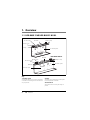
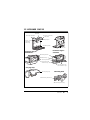
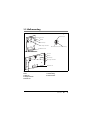
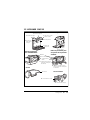
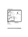
LIFE-BASE 1 NG
LIFE-BASE 1 NG XL
LIFE-BASE 1 NG XS
Portable system / Sistema de transporte
Device description and instructions for use
Descripción del aparato e instrucciones de manejo
English
3
Español
34
Contents
English
1.
1.1
1.2
1.3
1.4
1.5
2.
2.1
2.2
3.
3.1
4.
4.1
4.2
4.3
4.4
4.5
4.6
5.
5.1
5.2
5.3
5.4
6.
6.1
6.2
6.3
Overview . . . . . . . . . . . . . . . . . . . . 4
LIFE-BASE 1 NG/
LIFE-BASE 1 NG XL . . . . . . . . . . . . . 4
LIFE-BASE 1 NG XS . . . . . . . . . . . . 7
Wall mounting . . . . . . . . . . . . . . . 9
Special markings on the device . . 10
Safety information in these
instructions . . . . . . . . . . . . . . . . . 11
Description of device . . . . . . . . . 12
Intended use. . . . . . . . . . . . . . . . 12
Description of function . . . . . . . 12
Safety instructions . . . . . . . . . . . 14
Safety information . . . . . . . . . . . 14
Assembly . . . . . . . . . . . . . . . . . . . 16
Wall mounting . . . . . . . . . . . . . . 16
Device (not mounted in the case of
portable systems with an adapter
plate) . . . . . . . . . . . . . . . . . . . . . . 16
Protective bag (LIFE-BASE 1 NG/
LIFE-BASE 1 NG XL) . . . . . . . . . . . 16
Protective bag
(LIFE-BASE 1 NG XS) . . . . . . . . . . 17
Accessories bag (LIFE-BASE 1 NG/
LIFE-BASE 1 NG XL) . . . . . . . . . . . 19
LIFE-BASE 1 NG XS carrying strap 20
Operation . . . . . . . . . . . . . . . . . . 21
Hang portable system in wall
mounting . . . . . . . . . . . . . . . . . . 21
Hang portable system from
stretcher or hospital bed (LIFEBASE 1 NG/LIFE-BASE 1 NG XL) . . 22
Hang portable system from
stretcher or hospital bed
(LIFE-BASE 1 NG XS) . . . . . . . . . . 23
After use . . . . . . . . . . . . . . . . . . 23
Hygiene treatment . . . . . . . . . . . 24
Portable system . . . . . . . . . . . . . 24
Protective bag and
accessories bag . . . . . . . . . . . . . . 24
Attached parts . . . . . . . . . . . . . . 25
7.
7.1
7.2
7.3
8.
8.1
9.
9.1
9.2
9.3
10.
Function check . . . . . . . . . . . . . . .
Visual inspection. . . . . . . . . . . . .
Check catch . . . . . . . . . . . . . . . .
Check protective bag (if present)
Servicing . . . . . . . . . . . . . . . . . . . .
Disposal . . . . . . . . . . . . . . . . . . .
Scope of supply . . . . . . . . . . . . . .
General information . . . . . . . . . .
Standard scope of supply . . . . . .
Accessories and spare parts . . . .
Technical data . . . . . . . . . . . . . . .
11.
Warranty . . . . . . . . . . . . . . . . . . . . 31
12.
Declaration of conformity . . . . . 32
Contents
EN
26
26
26
26
27
27
28
28
28
29
30
3
1. Overview
1.1 LIFE-BASE 1 NG/LIFE-BASE 1 NG XL
LIFE-BASE 1 NG
4 Push-button
5 Handle
6 Lug for strap
3 Knurled screw
2 Hanger
1 Portable system
LIFE-BASE 1 NG XL
5 Handle
4 Push-button
3 Knurled screw
6 Lug for strap
1 Portable system
2 Hanger
7 Adapter plate
Key
1 Portable system
2 Hanger
The portable system is for storing a combination
of ventilation and therapy devices and the necessary components.
The hanger is for hanging the portable system
from a hospital bed or stretcher.
3 Knurled screw
The knurled screw is for fixing the hanger in
position.
4
EN
Overview
4 Push-button
6 Lug for strap
The push-buttons are used to fix the protective
bag to the portable system.
The strap for the portable system can be attached
to this lug.
5 Handle
7 Adapter plate
Use the handle to lift and carry the portable system.
The devices can be attached to the portable
system with the aid of the adapter plate.
Overview
EN
5
Protective bag
Rear view LIFE-BASE 1 NG
1
4
5
6
7
8
2
9
3
Rear view LIFE-BASE 1 NG XL
4
1
10
3
Key
1 Cable duct for charger interface
5 Side access compartment
2 Vibration dampers (only with
MEDUMAT Transport)
6 Viewing window
3 Hinge for bottom rail
4 Push-button to fix protective bag in
position
7 Velcro tab to access the control panel
8 Reflective strip
9 Opening for passing through a patient
tube system
10 Adapter plate
6
EN
Overview
1.2 LIFE-BASE 1 NG XS
Rear view
Front view
4 Handle
5 Charger interface
6 Lug for
tensioning
belt (long)
3 Lug for tensioning
belt (short)
2 Adapter plate
1 Portable system
7 Hinge for bottom rail
Protective bag for
ventilator
Protective bag for
defibrillator
8 Viewing window
9 Reflective strip
10 Side compartment
11 Velcro tape (with
ventilator only)
12 Loop for Velcro tape
(with ventilator only)
Carrying strap
13 Carrying strap
Tensioning belts
14 Tensioning belt (short)
15 Tensioning belt (long)
Overview
EN
7
1 Portable system
10 Side compartment
The portable system is for storing a device and its
components.
You can store the components and accessories of
the device in the side compartments. With the
ventilator, the left-hand side compartment provides access to the compressed gas connection
and space for the pressure tube, and the righthand side compartment provides access to the
device inlet filter. With the defibrillator, the lefthand side compartment provides access to the rechargeable battery, and the right-hand side compartment provides space for components such as
cables, for example.
2 Adapter plate
You can use the adapter plate to attach the device to the portable system.
3 Lug for tensioning belt (short)
You can attach a tensioning belt (short) to this
lug.
4 Handle
The portable system can be lifted and carried by
the handle. You can attach the carrying strap to
the handle.
5 Charger interface
You can charge the device on the portable system
using the charger interface.
11 Velcro tape (with ventilator only)
The Velcro tapes are used to attach the patient
tube system to the protective bag.
12 Loop for Velcro tape (with ventilator
only)
6 Lug for tensioning belt (long)
The Velcro tapes can be attached to these loops
which hold the patient tube system.
You can attach a tensioning belt (long) to this lug.
13 Carrying strap
7 Hinge for bottom rail
You can use the carrying strap to carry the
portable system on your shoulder.
This hinge is used to hang the portable system in
the wall mounting.
8 Viewing window
This is where to read off the device display when
the protective bag is closed.
9 Reflective strip
The reflective strip means the protective bag is
also visible in the dark.
8
EN
Overview
14 Tensioning belt (short)
The tensioning belt holds the pressure tube of the
ventilator if you are not using a protective bag.
15 Tensioning belt (long)
The tensioning belt holds the patient tube system
of the ventilator if you are not using a protective
bag.
1.3 Wall mounting
BASE-STATION 1 NG
Catch for wall mounting
6 Control pin
1 Catch
2 Bore
3 Guide pin
4 Charger interface
8 Catch cross-bar 7 Catch housing
5 Bottom rail
BASE-STATION Mini II
1 Catch
2 Bore
3 Guide pin
4 Charger interface
5 Bottom rail
1 Catch
6 Control pin
2 Bore
7 Catch housing
3 Guide pin
8 Catch cross-bar
4 Charger interface
5 Bottom rail
Overview
EN
9
1.4 Special markings on the device
1
2
3
4
Markings on the portable system
No.
Symbol
Significance
Information plate for portable system
1
Year of manufacture
SN
Serial number of portable system
CE symbol (confirms that the product conforms to applicable
European directives)
Portable system
2
Do not dispose of the portable system in domestic waste.
Markings on the wall mounting
No.
Symbol
Significance
Information plate for wall mounting
3
Year of manufacture
SN
Serial number of wall mounting
Do not dispose of the wall mounting with domestic waste.
Wall mounting
4
10
EN
Overview
Shows how the catch unlatches and the portable system is removed
from the wall mounting.
Markings on the carrying strap
Symbol
Significance
Do not iron
Wash at 30 °C
Do not dry in a tumble-dryer
Follow instructions for use
Maximum load
Markings on the packaging
Symbol
4
rh % 0-95
Significance
Permitted temperature for storage: -40 °C to +70 °C
Permitted humidity for storage: max. 95 % relative humidity
1.5 Safety information in these instructions
Safety information in these instructions for use is marked as follows:
Warning!
Warns of risk of injury and potential material damage.
Caution!
Warns of material damage and potentially false therapy results.
Note
Contains useful tips.
Overview
EN
11
2. Description of device
2.1 Intended use
The portable system is for storing a combination of devices from the MEDUMAT, MODUL
and MEDUCORE series, together with the required components (charger interface, tubes,
accessories bag, protective bag and electrical cables). This provides a user with mobile units
for treating respiratory disorders, for monitoring cardiovascular parameters and for resuscitation support.
The portable system can be latched in the associated BASE-STATION 1 NG and
BASE-STATION Mini II wall mountings to fix it securely to the wall.
The BASE-STATION 1 NG can be attached to various retaining devices in emergency
vehicles and in hospitals using a variety of attachment sets.
2.2 Description of function
All the devices provided are securely mounted on the portable system, making them easier
for you to transport and operate.
Using the hangers, you can hang the portable system from a stretcher, a hospital bed or a
standard hospital rail.
The portable system can be secured in a hospital environment or in an emergency vehicle
in conjunction with the BASE-STATION 1 NG or BASE-STATION Mini II wall mounting (see
“9.3 Accessories and spare parts” on page 29).
The portable system can also be secured to the ceiling in conjunction with the
BASE-STATION 1 NG roof mounting.
The BASE-STATION 1 NG and BASE-STATION Mini II wall mountings are assembled for
fixing to the wall. You can also expand them by adding the following attachment sets:
12
•
attachment set for standard hospital rail (BASE-STATION 1 NG and
BASE-STATION Mini II):
attach the wall mounting to a standard hospital rail in vehicles or in
hospital.
•
attachment set for fitting to a rail (BASE-STATION 1 NG):
attach the wall mounting to a rail (Ø 19 mm - 38 mm) in hospital. The
rail can be horizontally or vertically aligned.
EN
Description of device
•
supplementary attachment set for standard hospital rail
(BASE-STATION Mini II):
for attaching the wall mounting to a standard hospital rail in vehicles
You can remove the portable system from the wall mounting in just one maneuver.
Description of device
EN
13
3. Safety instructions
3.1 Safety information
Read these instructions for use carefully. It is a component part of the following portable
systems:
– LIFE-BASE 1 NG
– LIFE-BASE 1 NG XL
– LIFE-BASE 1 NG XS
The instructions for use must be available at all times. Use the portable system exclusively
for the intended purpose described (see “2.1 Intended use” on page 12).
For your own safety and the safety of your patients and in accordance with the
requirements of Directive 93/42/EEC, please note the following.
Use of the portable system
Warning!
Use the portable system only if you are medically trained and have received instruction in ventilation/aspiration. Severe physical damage may be caused by incorrect
use.
Caution!
• Before working with the portable system, you must have understood how to use
it.
• To avoid infection or bacterial contamination, follow the section entitled “6.
Hygiene treatment” on page 24.
• Do not use the portable system in the vicinity of a magnetic resonance
tomography (MRT) device.
• Use the portable system only for the intended use described (see “2.1 Intended
use” on page 12).
• During the journey/flight, the portable system must be hung in the wall mounting
intended for it, as otherwise it might fall over or be thrown around the vehicle.
The wall mounting must be securely attached. Follow the fitting instructions for
the wall mounting and the attachment set in question.
• Note that the portable system may not be loaded with an additional weight, e.g.
14
EN
Safety instructions
be leant on by a person, even once it is fixed in position. The portable system may
fall down and injure people or the device may be damaged.
Use of the wall mounting
Warning!
• Only the portable systems LIFE-BASE 1 NG, LIFE-BASE 1 NG XL,
LIFE-BASE 1 NG XS and LIFE-BASE Mini II should be suspended in the
BASE-STATION 1 NG and BASE-STATION Mini II wall mountings. The weight and
dimensions of these portable systems are exactly matched to the wall mountings.
• Hanging third-party products or adapters from other manufacturers is not
permitted, as this does not comply with the use in accordance with purpose of
this wall mounting.
Accessories/replacement parts
Caution!
If third-party items are used, functional failures may occur and fitness for use may be
restricted. Biocompatibility requirements may also not be met. Please note that in
such cases, any claim under warranty and liability will be voided if neither the accessories nor genuine replacement parts recommended in the instructions for use are
used.
Maintenance
Caution!
Have servicing and maintenance work carried out only by the manufacturer,
WEINMANN Emergency, or by trained staff.
Safety instructions
EN
15
4. Assembly
4.1 Wall mounting
The wall mounting for the portable system is ready for fitting to a wall. Using a suitable
attachment set (see Section 9.3 on page 29), you can also fit the wall mounting to a standard hospital rail or an ordinary rail (Ø 19 mm - 38 mm). When fitting, follow the relevant
fitting instructions enclosed with the wall mounting and the attachment sets in question.
4.2 Device (not mounted in the case of portable
systems with an adapter plate)
Note:
In most cases, the device is already mounted on the
portable system. You only need to mount the
device if you order a device separately.
1. Unscrew the adapter plate from the portable system.
2. Screw the adapter plate onto the rear of the device.
3. Screw the adapter plate and the device to the portable
system.
4.3 Protective bag (LIFE-BASE 1 NG/
LIFE-BASE 1 NG XL)
Attach protective bag
1. Place the protective bag on a firm, level surface.
2. Place the portable system inside, on the base of the
protective bag.
3. Attach the protective bag to the portable system using
the push-buttons.
16
EN
Assembly
4. If there is a ventilator on the portable system: Route the
patient tube system through the front opening in the
protective bag.
5. Close the velcro tabs on the front and rear.
Remove protective bag
1. Place the portable system on a firm, level surface.
2. Open the Velcro tabs on the front.
3. Open the push-buttons on the portable system and remove the portable system from the protective bag from
the rear.
4.4 Protective bag (LIFE-BASE 1 NG XS)
1. Place the portable system on a firm, level surface.
2. Remove all the device components.
3. On the ventilator: push the underside of the protective
bag into the space between the portable system and
the ventilator from the front and pull the top of the protective bag over the portable system as far as the
handle.
Alternatively
on the defibrillator: push the protective bag over the
portable system from the front.
Assembly
EN
17
4. Close the Velcro tab on the rear of the portable system.
5. Place the protective bag around the handle and close
the Velcro tabs under and next to the handle.
6. Connect all components to the device.
7. On the defibrillator: stow the electrodes under the
defibrillator.
8. Close the viewing window of the protective bag.
9. On the ventilator: clamp the patient tube system in the
space between the portable system and the ventilator
and fix it in position with the Velcro tabs on the protective bag.
10.Stow the accessories and small parts in the side
compartments of the protective bag
Remove protective bag
1. Place the portable system on a firm, level surface.
2. On the ventilator: open the Velcro tapes on the patient
tube system and pull it out of the space between the
portable system and the ventilator.
3. On the ventilator: open the viewing window of the
protective bag.
4. On the ventilator: detach the patient tube system.
5. Open the Velcro tab on the rear of the portable system.
18
EN
Assembly
6. Take the portable system out of the protective bag
backwards.
4.5 Accessories bag (LIFE-BASE 1 NG/
LIFE-BASE 1 NG XL)
There are four types of accessories bag:
– accessories bag for ventilators (fitted on the side)
– accessories bag for defibrillation/ventilation (fitted
on the side)
– accessories bag for defibrillation (fitted on the
portable system)
Fit accessories bag for ventilators
1. Open the Velcro tabs on the rear of the accessories bag.
2. Pass the Velcro tabs through the loops on the protective
bag.
3. Close the Velcro tabs on the rear of the accessories bag.
Assembly
EN
19
Fit accessories bag for defibrillation/ventilation
1. Hook the zip on the accessories bag into the zip on the
protective bag.
2. Close the zip.
Note
The accessories bag for defibrillation is attached to
the left of the protective bag, the accessories bag
for ventilation to the right of the protective bag.
Fit accessories bag for defibrillation
1. Press the accessories bag against the rear wall of the
portable system.
4.6 LIFE-BASE 1 NG XS carrying strap
1. Place the Velcro tab of the carrying strap around the
handle and close it.
20
EN
Assembly
5. Operation
5.1 Hang portable system in wall mounting
Hang portable system
Note
If you are using a protective bag, ensure that the
protective bag is properly located first.
1. To hang the portable system in the wall mounting,
place the portable system in the bottom rail.
Bottom rail
Warning!
– Risk of injury from loose portable system!
An inadequately secured portable system may fall
off or be thrown around the vehicle.
Control pin
– Ensure that you both hear and feel the catch
engage.
Catch
cross-bar
Catch
housing
– Check that the red control pin is flush with the top
edge of the catch housing and does not protrude.
2. Swivel the portable system towards the wall until you
hear and feel the catch cross-bar engage.
Operation
EN
21
Remove portable system
1. For unlatching, it is essential to grasp through the handle so that the portable system does not fall out of the
wall mounting and injure someone.
2. To unlatch, push the catch cross-bar upwards.
3. Swivel the portable system forwards a little way and lift
the portable system up off the bottom rail.
5.2 Hang portable system from stretcher or
hospital bed (LIFE-BASE 1 NG/
LIFE-BASE 1 NG XL)
You can also hang the portable system from a stretcher or
a hospital bed, as long as the rail diameter does not exceed
35 mm.
Caution!
Note that the portable system may not be loaded
with an additional weight, e.g. be leant on by a
person, even once it is fixed in position. The portable system may fall down and injure people or the
device may be damaged.
1. Undo the knurled screws.
2. Extend the hanger the required distance.
3. Tighten the knurled screws back up.
4. Hang the portable system from a stretcher, a hospital
bed or a standard rail.
Note
The portable system can only be hung back on a
wall mounting once you have pushed the hanger
back into its original position.
22
EN
Operation
5.3 Hang portable system from stretcher or
hospital bed (LIFE-BASE 1 NG XS)
You can only hang the portable system from a stretcher or
a hospital bed if you use a protective bag.
Caution!
Note that the portable system may not be loaded
with an additional weight, e.g. be leant on by a
person, even once it is fixed in position. The portable system may fall down and injure people or the
device may be damaged.
1. Open the magnetic closures on the straps on the rear of
the protective bag sideways.
2. Guide the straps round a rail of the stretcher or hospital
bed.
3. Close the magnetic closures.
5.4 After use
1.
Open the protective bag (if present).
2.
If present: Remove the pressure tube of the oxygen supply or stow it in the side
compartment of the protective bag.
3.
If present: Remove the patient tube system.
4.
Close the protective bag again (if present).
Operation
EN
23
6. Hygiene treatment
The portable system must be cleaned and disinfected after every use.
Always perform a function check afterwards (see “7. Function check” on page 26).
6.1 Portable system
The portable system is cleaned without its devices by the scouring and wiping method. You
can take all the devices off the portable system for this purpose.
•
See the instructions for use for the disinfectant used.
•
For disinfecting by wiping, we recommend terralin® protect.
•
We recommend wearing suitable gloves (e.g. household or disposable
gloves) for disinfecting.
Note
For further information on hygiene treatment and a list of all cleaning agents and
disinfectants which can be used, please see our Internet brochure at
www.weinmann-emergency.de.
6.2 Protective bag and accessories bag
Subject the bags to hygiene treatment in accordance with the table below:
Bag
Cleaning
PVC protective bag In hot water with a mild
PVC accessories bag detergent
CORDURA®
protective bag
CORDURA®
accessories bag
In hot water with a mild
detergent
Alternatively:
30 °C cycle in a washing
machine, no spin
Disinfecting
Sterilizing
Disinfectant wipe
Not permitted
30 °C cycle in a washing
machine (no spin), using a
suitable disinfecting additive
(disinfecting detergent or
impregnation agent)
Not permitted
Note: To prevent unattractive washing powder deposits, we recommend using a liquid
detergent.
24
EN
Hygiene treatment
6.3 Attached parts
Follow the instructions for cleaning, disinfecting and, if appropriate, sterilizing in the
associated instructions for use.
Hygiene treatment
EN
25
7. Function check
You must subject the portable system to a function check before it is used each time and
every time it has been dismantled, but in any case at least every 6 months. If you discover
faults during the function check, you may not use the portable system again until the faults
have been rectified. To guarantee that the portable system works perfectly, observe the following points.
7.1 Visual inspection
Look at the portable system closely. The portable system may not be damaged in any way
– which could result in parts coming loose
– which may restrict its function or
– which may cause injuries.
If you find any damage relating to one of these points, the portable system must be repaired or replaced.
7.2 Check catch
1.
Hang the portable system in the wall mounting and allow it to engage.
– The portable system must be located firmly in the wall mounting.
– The red control pin of the catch cross-bar must be flush with the top edge of the
catch housing.
2.
Check unlatching next. To do this, reach through the handle and pull the catch crossbar upwards.
– The catch cross-bar must be easy to move.
– The portable system may not catch on removal.
7.3 Check protective bag (if present)
Check push-buttons
Open and close the push-buttons.
– The push-buttons may not pop open again.
26
EN
Function check
Check Velcro tabs
Open the Velcro tabs.
– Both types of tape should be free of contamination.
Check magnetic closures
Open and close the magnetic closures.
– The magnetic closures may not pop open again.
8. Servicing
The portable system and the wall mounting require no servicing, but observe the intervals
for regular function checks on the attached parts. Look these up in the associated instructions for use if appropriate.
We recommend having maintenance measures such as servicing and repair work carried
out by the manufacturer, WEINMANN Emergency, or by specialist staff.
8.1 Disposal
LIFE-BASE 1 NG without charger interface
BASE-STATION 1 NG without charger interface
BASE-STATION Mini II without charger interface
Do not dispose of the device in domestic waste. To dispose of the device properly,
contact a licensed, certified disposal company. You can find an address from your environment officer or from your municipal authorities. The device packaging (cardboard and inserts) can be disposed of in paper recycling facilities.
LIFE-BASE 1 NG/LIFE-BASE 1 NG XL/LIFE-BASE 1 NG XS with charger
interface
BASE-STATION 1 NG with charger interface
BASE-STATION Mini II with charger interface
Do not dispose of the device in domestic waste. To dispose of the device properly,
contact a licensed, certified electronic scrap disposal merchant. You can find an address from your environment officer or from your municipal authorities. The device
packaging (cardboard and inserts) can be disposed of in paper recycling facilities.
Servicing
EN
27
9. Scope of supply
9.1 General information
The following applies to the portable system
•
The portable system is supplied fully assembled depending on the equipment variant.
•
Each portable system is supplied with these instructions for use.
The BASE-STATION 1 NG and BASE-STATION Mini II wall mountings are not included in the
scope of supply and should be ordered separately if required (see “9.3 Accessories and spare
parts” on page 29).
9.2 Standard scope of supply
Description
Order no.
LIFE-BASE 1 NG without charger interface and
MEDUMAT Transport without CO2 measurement
WM 9630
MEDUMAT Transport with CO2 measurement
WM 9635
LIFE-BASE 1 NG with charger interface and
MEDUMAT Transport without CO2 measurement
WM 9620
MEDUMAT Transport with CO2 measurement
WM 9625
LIFE-BASE 1 NG XL with charger interface and
MEDUCORE Standard Advanced
WM 9720
MEDUCORE Standard Advanced plus MEDUMAT Easy CPR
WM 9725
MEDUCORE Standard Advanced plus MEDUMAT Standard a
WM 9730
MEDUCORE Standard Pro
WM 9755
MEDUCORE Standard Pro plus MEDUMAT Easy CPR
WM 9760
MEDUCORE Standard Pro plus MEDUMAT Standard a
WM 9765
MEDUCORE Standard Basic
WM 9735
28
EN
Scope of supply
Description
Order no.
MEDUCORE Standard Basic plus MEDUMAT Easy CPR
WM 9740
MEDUCORE Standard Basic plus MEDUMAT Standard a
WM 9745
MEDUMAT
Standard2
WM 9400
2
WM 9405
MEDUMAT Standard plus MEDUCORE Standard
LIFE-BASE 1 NG XS with charger interface and
2
MEDUMAT Standard
WM 9870
MEDUCORE Standard Basic
WM 9882
MEDUCORE Standard Advanced
WM 9883
MEDUCORE Standard Pro
WM 9880
9.3 Accessories and spare parts
You can order accessories and spare parts separately if required. A current list of accessories
and spare parts can be ordered on the Internet at www.weinmann-emergency.de or via your
dealer.
Scope of supply
EN
29
10. Technical data
LIFE-BASE 1 NG
Product class
to 93/42/EEC
Class I
Standards applied
EN 1789
Dimensions (without
protective bag)
W x H x D in mm
415 x 240 x 140 (LIFE-BASE 1 NG)
427 x 240 x 140 (LIFE-BASE 1 NG XL)
220 x 230 x 136 (LIFE-BASE 1 NG XS)
Weight
Empty:
LIFE-BASE 1 NG: approx. 2.0 kg
LIFE-BASE 1 NG XL: approx. 2.2 kg
LIFE-BASE 1 NG XS: approx. 1.0 kg
With equipment:
LIFE-BASE 1 NG and LIFE-BASE 1 NG XL: max. 7.0 kg
LIFE-BASE 1 NG XS: max. 5.0 kg
Maximum load for
carrying strap
5 kg
Temperature range
– operation
– storage
–18 °C to +60 °C
–40 °C to +70 °C
Note
The temperature range may be limited by any devices fitted!
Electrical rating for
charger interface
12 V DC, Imax = 8 A
The right to make design modifications is reserved
30
EN
Technical data
11. Warranty
WEINMANN Emergency gives the customer a limited manufacturer warranty on new genuine WEINMANN
Emergency products and any replacement part fitted by
WEINMANN Emergency in accordance with the warranty
conditions applicable to the product in question and in accordance with the warranty periods from date of purchase
as listed below. The warranty conditions can be downloaded from www.weinmann-emergency.de on the Internet.
We can also send you the warranty conditions on request.
In the event of a claim under warranty, contact your
specialist dealer.
Product
Warranty period
WEINMANN Emergency devices including
accessories (exception: masks) for oxygen 2 years
and emergency medicine
Masks including accessories,
rechargeable battery, batteries (unless
there is information to the contrary in the 6 months
technical documentation), sensors, tube
systems
Disposable products
None
Warranty
EN
31
12. Declaration of conformity
WEINMANN Emergency Medical Technology GmbH + Co. KG declares herewith that the
product complies fully with the respective regulations of the Medical Device Directive 93/42/
EEC. The unabridged text of the Declaration of Conformity can be found on our website at
www.weinmann-emergency.de
32
EN
Declaration of conformity
Indice
Español
1.
1.1
1.2
1.3
1.4
1.5
2.
2.1
2.2
3.
3.1
4.
4.1
4.2
4.3
4.4
4.5
4.6
5.
5.1
5.2
5.3
5.4
Vista general . . . . . . . . . . . . . . . . 34
LIFE-BASE 1 NG/
LIFE-BASE 1 NG XL . . . . . . . . . . . . 34
LIFE-BASE 1 NG XS . . . . . . . . . . . 37
Soporte mural. . . . . . . . . . . . . . . 39
Señalización especial en el
aparato . . . . . . . . . . . . . . . . . . . . 40
Indicaciones de seguridad en
estas instrucciones . . . . . . . . . . . . 41
Descripción del aparato . . . . . . . 42
Uso conforme a lo dispuesto. . . . 42
Descripción del funcionamiento . 42
Indicaciones de seguridad . . . . . 44
Disposiciones de seguridad . . . . . 44
Montaje . . . . . . . . . . . . . . . . . . . . 46
Soporte mural. . . . . . . . . . . . . . . 46
Aparato (sin montar, para
sistemas de transporte con placa
adaptadora) . . . . . . . . . . . . . . . . . 46
Bolsa de protección
(LIFE-BASE 1 NG/
LIFE-BASE 1 NG XL) . . . . . . . . . . . 47
Bolsa de protección
(LIFE-BASE 1 NG XS) . . . . . . . . . . 47
Bolsa de accesorios
(LIFE-BASE 1 NG/
LIFE-BASE 1 NG XL) . . . . . . . . . . . 49
Correa LIFE-BASE 1 NG XS . . . . . 50
Manejo . . . . . . . . . . . . . . . . . . . . . 51
Enganchar el sistema de
transporte en el soporte mural . . . 51
Enganchar el sistema de
transporte a la camilla o la cama
de hospital (LIFE-BASE 1 NG/
LIFE-BASE 1 NG XL) . . . . . . . . . . . 52
Enganchar el sistema de transporte
a la camilla o la cama de hospital
(LIFE-BASE 1 NG XS) . . . . . . . . . . 53
Después del uso . . . . . . . . . . . . . 53
6.
6.1
6.2
8.
8.1
9.
9.1
9.2
9.3
10.
Acondicionamiento higiénico . . . 54
Sistema de transporte . . . . . . . . . 54
Bolsa de protección y bolsa de
accesorios . . . . . . . . . . . . . . . . . . 55
Piezas montables . . . . . . . . . . . . 55
Control del funcionamiento . . . . 56
Control visual . . . . . . . . . . . . . . . 56
Comprobar el enclavamiento . . . 56
Comprobar la bolsa de
protección (si dispone de ella) . . . 57
Mantenimiento . . . . . . . . . . . . . . 58
Eliminación . . . . . . . . . . . . . . . . . 58
Volumen de suministro . . . . . . . . 59
Indicaciones generales . . . . . . . . 59
Volumen de suministro de serie . 59
Accesorios y piezas de repuesto . 60
Datos técnicos . . . . . . . . . . . . . . . 61
11.
Garantía . . . . . . . . . . . . . . . . . . . . 62
12.
Declaración de conformidad . . . 63
6.3
7.
7.1
7.2
7.3
Indice
ES
33
1. Vista general
1.1 LIFE-BASE 1 NG/LIFE-BASE 1 NG XL
LIFE-BASE 1 NG
4 Botón a presión
5 Asa de transporte
6 Ojal para correa
3 Tornillo moleteado
2 Ángulo de
sujeción
1 Sistema de
transporte
5 Asa de transporte
4 Botón a presión
3 Tornillo moleteado
LIFE-BASE 1 NG XL
6 Ojal para correa
1 Sistema de transporte
2 Ángulo de sujeción
7 Placa adaptadora
Leyenda
1 Sistema de transporte
2 Ángulo de sujeción
El sistema de transporte sirve para el alojamiento
de una combinación de aparatos de respiración
artificial y de terapia, así como los componentes
necesarios.
El ángulo de sujeción sirve para enganchar el sistema de transporte en una cama de hospital o una
camilla.
3 Tornillo moleteado
El tornillo moleteado sirve para fijar el ángulo de
sujeción.
34
ES
Vista general
4 Botón a presión
6 Ojal para correa
Con los botones a presión puede fijar la bolsa de
protección al sistema de transporte.
En este ojal puede fijar la correa para el sistema de
transporte.
5 Asa de transporte
7 Placa adaptadora
Con el asa de transporte puede levantar y llevar el
sistema de transporte.
Los aparatos pueden fijarse al sistema de
transporte con la ayuda de la placa adaptadora.
Vista general
ES
35
Bolsa de protección
Vista posterior LIFE-BASE 1 NG
5
1
4
6
7
8
2
3
9
Vista posterior LIFE-BASE 1 NG XL
4
1
10
3
Leyenda
1 Paso de cable para la interfaz de carga
5 Compartimento de acceso lateral
2 Amortiguadores (exclusivamente en
MEDUMAT Transport)
6 Mirilla
3 Eje para la guía de asiento inferior
4 Botón a presión para fijar la bolsa de
protección
7 Cierre de velcro para abrir el panel de
mando frontal
8 Tiras reflectantes
9 Orificio para el paso de un sistema de
mangueras para pacientes
10 Placa adaptadora
36
ES
Vista general
1.2 LIFE-BASE 1 NG XS
Vista posterior
Vista frontal
4 Asa de transporte
5 Interfaz de carga
6 Ojal para la
correa tensora (larga)
3 Ojal para la correa
tensora (corta)
2 Placa adaptadora
1 Sistema de
transporte
7 Eje para el riel de
sujeción inferior
Bolsa de protección
para el desfibrilador
8 Mirilla
Bolsa de protección para
el aparato de respiración
artificial
9 Tiras reflectantes
10 Compartimento
lateral
11 Cinta de velcro (sólo en
el aparato de respiración artificial)
12 Lazo para la cinta de velcro
(sólo en el aparato de respiración artificial)
Correa
13 Correa
Correa tensora
14 Correa tensora (corta)
15 Correa tensora (larga)
Vista general
ES
37
1 Sistema de transporte
10 Compartimento lateral
El sistema de transporte sirve para alojar un
aparato y sus componentes.
Puede almacenar los componentes y accesorios
del aparato en los compartimentos laterales. Para
el aparato de respiración artificial, el compartimento de la izquierda permite acceder a la conexión de gas a presión y ofrece espacio para el
tubo de presión, y el compartimento de la derecha permite acceder a la batería y al filtro de entrada del aparato. Para el desfibrilador, el
compartimento de la izquierda permite acceder a
la batería y el compartimento de la derecha ofrece
espacio para los componentes, como p.ej. cables.
2 Placa adaptadora
Puede fijar el aparato al sistema de transporte con
la ayuda de la placa adaptadora.
3 Ojal para la correa tensora (corta)
Puede fijar a este ojal la correa tensora (corta).
4 Asa de transporte
Con el asa de transporte puede levantar y llevar el
sistema de transporte. Puede fijar la correa al asa
de transporte.
5 Interfaz de carga
Con la interfaz de carga, puede cargar el aparato
en el sistema de transporte.
6 Ojal para la correa tensora (larga)
Puede fijar a este ojal la correa tensora (larga).
7 Eje para el riel de sujeción inferior
Este eje sirve para colgar el sistema de transporte
en el soporte mural.
11 Cinta de velcro (sólo en el aparato de
respiración artificial)
Las cintas de velcro fijan el sistema de tubos
flexibles para el paciente a la bolsa de protección.
12 Lazo para la cinta de velcro (sólo en el
aparato de respiración artificial)
Las cintas de velcro que sujetan el sistema de
tubos flexibles para el paciente pueden fijarse a
estos lazos.
13 Correa
8 Mirilla
Con la correa puede llevar el sistema de
transporte al hombro.
Le permite leer la pantalla del dispositivo con la
bolsa de protección cerrada.
14 Correa tensora (corta)
9 Tiras reflectantes
La bolsa de protección tiene tiras reflectantes
visibles en la oscuridad.
La correa tensora sujeta el tubo de presión del
aparato de respiración artificial, en caso de que
no utilice una bolsa de protección.
15 Correa tensora (larga)
La correa tensora sujeta el sistema de tubos flexibles para el paciente del aparato de respiración
artificial, en caso de que no utilice una bolsa de
protección.
38
ES
Vista general
1.3 Soporte mural
BASE-STATION 1 NG
Bloqueo soporte mural
6 Pasador de
control
1 Bloqueo
2 Agujero
3 Pasador de guía
4 Interfaz de carga
5 Guía de asiento
inferior
8 Eje de
enclavamiento
7 Carcasa de
enclavamiento
BASE-STATION Mini II
1 Bloqueo
2 Agujero
3 Pasador de guía
4 Interfaz de carga
5 Guía de asiento inferior
1 Bloqueo
6 Pasador de control
2 Agujero
7 Carcasa de enclavamiento
3 Pasador de guía
8 Eje de enclavamiento
4 Interfaz de carga
5 Guía de asiento inferior
Vista general
ES
39
1.4 Señalización especial en el aparato
1
2
3
4
Señalización en el sistema de transporte
N.º
Símbolo
Significado
Letrero del aparato, sistema de transporte
1
Año de fabricación
SN
Número de serie del sistema de transporte
Marca CE (confirma que el producto cumple las directivas europeas
vigentes)
Sistema de transporte
2
No elimine el sistema de transporte tirándolo a la basura doméstica.
Señalización en el soporte mural
N.º
Símbolo
Significado
Letrero del aparato, soporte mural
3
Año de fabricación
SN
Número de serie del soporte mural
No elimine el soporte mural tirándolo a la basura doméstica.
Soporte mural
4
40
ES
Vista general
Indica cómo puede liberar el enclavamiento y desprender el sistema
de transporte del soporte mural.
Indicaciones en la correa
Símbolo
Significado
No planchar
Lavar a 30 ºC
No secar en secadora
Tener en cuenta el manual de instrucciones
Carga máxima
Señalización en el embalaje
Símbolo
4
de hum. rel. % 0-95
Significado
Temperatura admisible de almacenamiento: - 40 °C a +70 °C
Humedad atmosférica admisible de almacenamiento: 95 % máximo de
humedad relativa
1.5 Indicaciones de seguridad en estas
instrucciones
En este manual de instrucciones se señalizan las indicaciones de seguridad de la siguiente
forma:
¡Advertencia!
Advierte de la existencia de peligro de lesiones y posibles daños materiales.
¡Precaución!
Advierte de daños materiales y posiblemente de resultados de terapia incorrectos.
Nota:
Contiene consejos útiles.
Vista general
ES
41
2. Descripción del aparato
2.1 Uso conforme a lo dispuesto
El sistema de transporte sirve para alojar una combinación de aparatos de las series
MEDUMAT, MODUL y MEDUCORE, así como los componentes necesarios (interfaz de carga, tubos, bolsa de accesorios y de protección, cables eléctricos). De este modo, el usuario
dispone de unidades móviles para el tratamiento de trastornos respiratorios, el seguimiento
de los parámetros cardiovasculares y de asistencia en la reanimación.
Para una fijación segura, el sistema de transporte se puede enclavar en los soportes murales
correspondientes BASE-STATION 1 NG y BASE-STATION Mini II.
Mediante diversos juegos de montaje, la BASE-STATION 1 NG se puede montar en diferentes dispositivos de soporte en los medios de salvamento y en el ámbito hospitalario.
2.2 Descripción del funcionamiento
Todos los aparatos previstos están montados de forma fija en el sistema de transporte.
De este modo, el transporte y el manejo resultan más fáciles.
Puede enganchar el sistema de transporte mediante los ángulos de sujeción a una camilla,
una cama de hospital o un riel normalizado en la clínica.
En combinación con el soporte mural BASE-STATION 1 NG o BASE-STATION Mini II, el sistema de transporte se puede fijar con seguridad en el ámbito hospitalario o en un medio
de salvamento (véase “9.3 Accesorios y piezas de repuesto” en la página 60).
El sistema de transporte también puede fijarse al techo con el soporte de techo
BASE-STATION 1 NG.
Los soportes murales BASE-STATION 1 NG y BASE-STATION Mini II están confeccionados
para la sujeción mural. El soporte mural se puede ampliar además con los siguientes juegos
de montaje:
42
•
Juego de montaje de riel normalizado de hospital (BASE-STATION 1 NG
y BASE-STATION Mini II):
Fijación del soporte mural a un riel normalizado de hospital en vehículos
o en el hospital.
ES
Descripción del aparato
•
Juego de montaje para montaje en barra (BASE-STATION 1 NG):
Fijación del soporte mural a una barra (Ø 19 mm - 38 mm) en el hospital.
La barra puede estar orientada horizontal o vertical.
•
Juego de montaje complementario para riel normalizado de hospital
(BASE-STATION Mini II):
Fijación del soporte mural a un riel normalizado de hospital en vehículos
Puede retirar el sistema de transporte del soporte mural con un asidero.
Descripción del aparato
ES
43
3. Indicaciones de seguridad
3.1 Disposiciones de seguridad
Lea con atención estas instrucciones de uso. Forman parte de los siguientes sistemas de
transporte:
– LIFE-BASE 1 NG
– LIFE-BASE 1 NG XL
– LIFE-BASE 1 NG XS
Las instrucciones de uso deben estar disponibles en todo momento. Utilice el sistema de
transporte exclusivamente para el fin descrito (véase “2.1 Uso conforme a lo dispuesto” en
la página 42).
Por su propia seguridad personal, así como por la de sus pacientes, y para cumplir con los
requerimientos estipulados en la Directiva 93/42/CEE, observe lo siguiente:
Uso del sistema de transporte
¡Advertencia!
Utilice el sistema de transporte sólo si cuenta con formación médica y ha recibido instrucción en la técnica de respiración artificial y de aspiración. Su utilización incorrecta
puede provocar lesiones personales graves.
¡Precaución!
• Antes de trabajar con el sistema de transporte, debe haber comprendido su
manejo.
• Para evitar una infección o una contaminación bacteriana, tenga en cuenta el
apartado “6. Acondicionamiento higiénico” en la página 54.
• No utilice el sistema de transporte en la proximidad de un equipo de tomografía
por resonancia magnética (MRT).
• Utilice el sistema de transporte únicamente para la finalidad de uso descrita (véase
“2.1 Uso conforme a lo dispuesto” en la página 42).
• Durante el viaje/vuelo, el sistema de transporte se tiene que enganchar en el
soporte mural previsto al efecto; de lo contrario podría volcar o ser proyectado por
el vehículo. El soporte mural debe estar fijado con seguridad. Siga las instrucciones
de montaje del soporte mural y del correspondiente juego de montaje.
44
ES
Indicaciones de seguridad
• Observe que el sistema de transporte, incluso cuando está fijado, no se puede
cargar con un peso adicional, p. ej. apoyando el cuerpo sobre él. El sistema de
transporte podría caer y lesionar a personas, o se podría dañar el aparato.
Uso del soporte mural
¡Advertencia!
• Los sistemas de transporte LIFE-BASE 1 NG, LIFE-BASE 1 NG XL,
LIFE-BASE 1 NG XS y LIFE-BASE Mini II solo pueden engancharse en los soportes
murales BASE-STATION 1 NG y BASE-STATION Mini II. El peso y las dimensiones
de estos sistemas de transporte están adaptados exactamente al soporte mural.
Por lo tanto, no se permite utilizar otros sistemas de transporte.
• No se permite enganchar productos o adaptadores de otros fabricantes, dado que
esto no corresponde al uso conforme a lo dispuesto de este soporte mural.
Accesorios/piezas de repuesto
¡Precaución!
Si se utilizan artículos de otros fabricantes, pueden darse fallos en el funcionamiento
y limitarse la aptitud para el uso. Además pueden no cumplirse los requerimientos de
biocompatibilidad. Tenga en cuenta que en estos casos perderá cualquier derecho de
garantía o de indemnización si no utiliza los accesorios recomendados en el manual
de instrucciones ni las piezas de repuesto originales.
Reparación
¡Precaución!
Únicamente debe dejar que realicen las inspecciones y los trabajos de reparación el
fabricante WEINMANN Emergency o el personal experto.
Indicaciones de seguridad
ES
45
4. Montaje
4.1 Soporte mural
El soporte mural para el sistema de transporte está confeccionado para su montaje a la pared. Con un juego de montaje adecuado (ver capítulo 9.3 en la página 60) puede montar
también el apoyo mural en un riel normalizado de hospital o en una barra (Ø 19 mm - 38
mm). Para el montaje siga las instrucciones de montaje correspondientes, que se adjuntan
tanto al apoyo mural como al correspondiente juego de montaje.
4.2 Aparato (sin montar, para sistemas de
transporte con placa adaptadora)
Nota:
En la mayoría de los casos el aparato ya está montado en el sistema de transporte. Sólo tendrá que
montar el aparato si pide un aparato por separado.
1. Destornille la placa adaptadora del sistema de
transporte.
2. Atornille la placa adaptadora a la parte trasera del
aparato.
3. Atornille la placa adaptadora con el aparato en el
sistema de transporte.
46
ES
Montaje
4.3 Bolsa de protección (LIFE-BASE 1 NG/
LIFE-BASE 1 NG XL)
Fijar la bolsa de protección
1. Coloque la bolsa de protección sobre una superficie
plana y firme.
2. Ponga dentro el sistema de transporte, sobre el fondo
de la bolsa de protección.
3. Fije la bolsa de protección al sistema de transporte
mediante los botones a presión.
4. Si se aloja un aparato de respiración en el sistema de
transporte: Pase el sistema de mangueras para pacientes a través del orificio situado delante en la bolsa de
protección.
5. Cierre los cierres de velcro en la parte delantera y
trasera.
Quitar la bolsa de protección
1. Coloque el sistema de transporte sobre una superficie
plana y firme.
2. Abra los cierres de velcro en la parte delantera.
3. Abra los botones a presión situados sobre el sistema de
transporte y saque el sistema de transporte hacia atrás
de la bolsa de protección.
4.4 Bolsa de protección (LIFE-BASE 1 NG XS)
1. Coloque el sistema de transporte sobre una superficie
plana y firme.
2. Retire todos los componentes del aparato.
3. Para el aparato de respiración artificial: deslice la parte
inferior de la bolsa de protección por delante en el hueco entre el sistema de transporte y el aparato de respiración artificial y pase la parte superior de la bolsa de
protección por encima del sistema de transporte hasta
Montaje
ES
47
el asa de transporte.
o bien
Para el desfibrilador: deslice la bolsa de protección por
delante y pasándola por encima del sistema de transporte.
4. Cierre la cinta de velcro situada en la parte trasera del
sistema de transporte.
5. Coloque la bolsa de protección alrededor del asa de
transporte y cierre las cintas de velcro de debajo y al
lado del asa.
6. Conecte todos los componentes al aparato.
7. Para el desfibrilador: guarde los electrodos en la parte
inferior del desfibrilador.
8. Cierre la mirilla de la bolsa de protección.
9. Para el aparato de respiración artificial: fije el sistema de
tubos flexibles para el paciente en el hueco entre el sistema de transporte y el aparato de respiración artificial
y sujételo a la bolsa de protección con las cintas de
velcro.
10.Guarde los accesorios y las piezas pequeñas en los
compartimentos laterales de la bolsa de protección.
Retirar la bolsa de protección
1. Coloque el sistema de transporte sobre una superficie
plana y firme.
2. Para el aparato de respiración artificial: abra las cintas
de velcro del sistema de tubos flexibles para el paciente
y sáquelo del hueco entre el sistema de transporte y el
aparato de respiración artificial.
3. Para el aparato de respiración artificial: abra la mirilla de
la bolsa de protección.
48
ES
Montaje
4. Para el aparato de respiración artificial: retire el sistema
de tubos flexibles para el paciente.
5. Abra la cinta de velcro situada en la parte trasera del
sistema de transporte.
6. Abra los cierres de velcro de debajo y al lado del asa de
transporte y retire la bolsa de protección del asa.
7. Tire del sistema de transporte hacia atrás para retirarlo
de la bolsa de protección.
4.5 Bolsa de accesorios (LIFE-BASE 1 NG/
LIFE-BASE 1 NG XL)
Hay cuatro tipos de bolsas de accesorios:
– bolsa de accesorios para aparatos de respiración
artificial (montada lateralmente)
– bolsa de accesorios para desfibrilación/respiración
(montada lateralmente)
– bolsa de accesorios para desfibrilación (montada
en el sistema de transporte)
Montaje
ES
49
Montar bolsa de accesorios para aparatos de respiración artificial
1. Abra los cierres de velcro en la parte trasera de la bolsa
de accesorios.
2. Pase la cinta de velcro a través del lazo en la bolsa de
protección.
3. Cierre los cierres de velcro en la parte trasera de la bolsa
de accesorios.
Montar bolsa de accesorios para desfibrilación/respiración
1. Enganche la cremallera de la bolsa de accesorios en la
cremallera de la bolsa de protección.
2. Cierre la cremallera.
Nota:
la bolsa de accesorios para la desfibrilación se sujeta a la izquierda de la bolsa de protección, la bolsa
de accesorios para la respiración, a la derecha de la
bolsa de protección.
Montar bolsa de accesorios para la desfibrilación
1. Presione la bolsa de accesorios contra la pared posterior
del sistema de transportes.
4.6 Correa LIFE-BASE 1 NG XS
1. Coloque la cinta de velcro de la correa alrededor del asa
de transporte y ciérrela.
50
ES
Montaje
5. Manejo
5.1 Enganchar el sistema de transporte en el
soporte mural
Enganchar el sistema de transporte
Nota:
Si utiliza una bolsa de protección, antes de la utilización preste atención a que la bolsa de protección
esté correctamente sujeta.
1. Para enganchar el sistema de transporte en el soporte
mural, coloque el sistema de transporte en la guía de
asiento inferior.
¡Advertencia!
Guía de asiento
inferior
Pasador de control
– ¡Peligro de lesiones por sistema de transporte
suelto!
Un sistema de transporte que no esté
suficientemente fijado, puede caer o ser
proyectado por el vehículo.
– Asegúrese de que el enclavamiento quede
encajado de forma audible y perceptible.
Eje de
enclavamiento
Carcasa de
enclavamiento
– Compruebe que el pasador de control rojo está
enrasado con la parte superior de la carcasa de
enclavamiento y no sobresale.
2. Gire el sistema de transporte en dirección a la pared,
hasta que el eje de enclavamiento quede encajado de
forma audible y visible.
Manejo
ES
51
Sacar el sistema de transporte
1. Al desenclavar el sistema, es absolutamente necesario
pasar la mano a través del asidero, con el fin de evitar
que el sistema de transporte pueda caerse del soporte
mural y causar lesiones a alguien.
2. Para desbloquear, presione el eje de enclavamiento
hacia arriba.
3. Gire el sistema de transporte ligeramente hacia delante
y sáquelo hacia arriba de la guía de asiento inferior.
5.2 Enganchar el sistema de transporte a la
camilla o la cama de hospital
(LIFE-BASE 1 NG/LIFE-BASE 1 NG XL)
También puede enganchar el sistema de transporte a una
camilla o una cama de hospital. El diámetro del tubo no
debe ser mayor de 35 mm.
¡Precaución!
Observe que el sistema de transporte, incluso
cuando está fijado, no se puede cargar con un peso
adicional, p. ej. apoyando el cuerpo sobre él. El sistema de transporte podría caer y lesionar a personas, o se podría dañar el aparato.
1. Afloje los tornillos moleteados.
2. Extraiga el ángulo de sujeción a la distancia necesaria.
3. Apriete de nuevo los tornillos moleteados.
4. Enganche el sistema de transporte a una camilla, una
cama de hospital o un riel normalizado.
Nota:
Sólo podrá volver a enganchar el sistema de transporte en un soporte mural, cuando que haya devuelto a su posición original el ángulo de sujeción.
52
ES
Manejo
5.3 Enganchar el sistema de transporte a la
camilla o la cama de hospital
(LIFE-BASE 1 NG XS)
Si utiliza una bolsa de protección, sólo puede enganchar el
sistema de transporte a una camilla o cama de hospital.
¡Precaución!
Observe que el sistema de transporte, incluso
cuando está fijado, no se puede cargar con un peso
adicional, p. ej. apoyando el cuerpo sobre él. El sistema de transporte podría caer y lesionar a personas, o se podría dañar el aparato.
1. Los cierres magnéticos de las correas, situados en la
parte posterior de la bolsa de protección, se abren hacia
los lados.
2. Colocar la correa alrededor de una barra de la camilla o
cama de hospital.
3. Bloquear los cierres magnéticos.
5.4 Después del uso
1.
Abra la bolsa de protección (si dispone de ella).
2.
Si dispone de él: Retire el tubo de presión del suministro de oxígeno o guárdelo en el
compartimento lateral de la bolsa de protección.
3.
Si dispone de él: Retire el sistema de mangueras para pacientes.
4.
Cierre la bolsa de protección (si dispone de ella).
Manejo
ES
53
6. Acondicionamiento higiénico
Después de cada uso es preciso limpiar y desinfectar el sistema de transporte.
A continuación, debe llevar a cabo un control del funcionamiento (véase “7. Control del
funcionamiento” en la página 56).
6.1 Sistema de transporte
El sistema de transporte, sin aparatos, se limpia según el procedimiento de fregado y
frotamiento. Para este fin, puede quitar todos los aparatos del sistema de transporte.
•
Tenga en cuenta el manual de instrucciones del agente desinfectante
utilizado.
•
Para el frotado de desinfección recomendamos terralin® protect.
•
Recomendamos llevar guantes adecuados (p. ej., guantes para fregar o
guantes desechables) para la desinfección.
Nota:
Encontrará más información sobre el tratamiento higiénico y una lista de todos los
productos limpiadores y agentes desinfectantes utilizables en un folleto en nuestra
página web en www.weinmann-emergency.de.
54
ES
Acondicionamiento higiénico
6.2 Bolsa de protección y bolsa de accesorios
Prepare las bolas según la siguiente tabla:
Bolsa
Limpieza
Desinfección
Esterilización
Bolsa de protección
PVC
Bolsa de accesorios
PVC
En agua caliente con un
detergente suave
Desinfección por frotamiento
No permitido
Bolsa de protección
CORDURA®
Bolsa de accesorios
CORDURA®
En agua caliente con un
detergente suave
o bien
ciclo de aclarado a 30 °C
sin centrifugar en la
lavadora
Ciclo de aclarado a 30 °C sin
centrifugar en la lavadora,
añada un desinfectante
adecuado (detergente
desinfectante o impregnante)
No permitido
Nota: Para evitar depósitos antiestéticos de detergente en polvo recomendamos utilizar
detergente líquido.
6.3 Piezas montables
Observe las indicaciones para la limpieza, la desinfección y, en caso necesario, la
esterilización, en las instrucciones de uso correspondientes.
Acondicionamiento higiénico
ES
55
7. Control del funcionamiento
El sistema de transporte se tiene que someter a un control de funcionamiento antes de
cada uso y después de cada desmontaje, pero como mínimo cada 6 meses. Si se descubrieran anomalías en el control de funcionamiento, no debe utilizar el sistema de transporte
hasta que hayan sido eliminadas las anomalías. Para garantizar el correcto funcionamiento
del sistema de transporte, observe los puntos siguientes:
7.1 Control visual
Examine detalladamente el sistema de transporte. El sistema de transporte no debe
presentar ningún daño,
– como consecuencia del cual se pudieran desprender elementos,
– que puedan limitar el funcionamiento o
– que pudieran causar lesiones.
En caso de que detecte defectos en los cuales fuera aplicable alguno de los puntos citados,
es necesario que repare o cambie el sistema de transporte.
7.2 Comprobar el enclavamiento
1.
Enganche el sistema de transporte en el soporte mural y encájelo.
– El sistema de transporte debe estar sujeto firmemente en el soporte mural.
– El pasador de control rojo del eje de enclavamiento tiene que estar enrasado con la
parte superior de la carcasa de enclavamiento.
2.
Compruebe a continuación el desenclavamiento. Para ello, pase la mano por el asidero
y tire del eje de enclavamiento hacia arriba.
– El eje de enclavamiento debe poder accionarse con facilidad.
– El sistema de transporte no debe quedar bloqueada al retirarlo.
56
ES
Control del funcionamiento
7.3 Comprobar la bolsa de protección (si dispone
de ella)
Comprobar los botones a presión
Abra y cierre los botones a presión.
– Los botones a presión no se deben abrir de nuevo.
Comprobar los cierres de velcro
Abra los cierres de velcro.
– La cinta afelpada y la cinta de ganchitos deben estar libres de suciedad.
Control de los cierres magnéticos
Desbloquee y bloquee los cierres magnéticos.
– Los cierres magnéticos no se deben abrir de nuevo.
Control del funcionamiento
ES
57
8. Mantenimiento
El sistema de transporte y el soporte mural no necesitan mantenimiento alguno. Sin embargo, observe los plazos del control periódico del funcionamiento para las piezas acopladas. En caso necesario, consulte las instrucciones de uso correspondientes.
Le aconsejamos que encargue las tareas de mantenimiento, tales como inspecciones y trabajos de reparación, al fabricante WEINMANN Emergency o a personal experto.
8.1 Eliminación
LIFE-BASE 1 NG sin interfaz de carga
BASE-STATION 1 NG sin interfaz de carga
BASE-STATION Mini II sin interfaz de carga
No elimine el aparato tirándolo a la basura doméstica. Para la eliminación correcta del aparato, diríjase a una empresa de eliminación de residuos autorizada y certificada. Pregunte
la dirección a su delegado de medio ambiente o en su ayuntamiento. El embalaje del aparato (el cartón y las piezas interiores) puede eliminarlo en el reciclaje de papel.
LIFE-BASE 1 NG/LIFE-BASE 1 NG XL/LIFE-BASE 1 NG XS con interfaz de
carga
BASE-STATION 1 NG con interfaz de carga
BASE-STATION Mini II con interfaz de carga
No elimine el aparato tirándolo a la basura doméstica. Para la eliminación correcta
del aparato, diríjase a una empresa de reciclaje de electrónica autorizada y certificada. Pregunte la dirección a su delegado de medio ambiente o en su ayuntamiento.
El embalaje del aparato (el cartón y las piezas interiores) puede eliminarlo en el reciclaje de papel.
58
ES
Mantenimiento
9. Volumen de suministro
9.1 Indicaciones generales
Para el sistema de transporte es aplicable:
•
El sistema de transporte se suministra completamente montado según la
variante de equipamiento.
•
Cada sistema de transporte se suministra con estas instrucciones de
manejo.
Los soportes murales BASE-STATION 1 NG y BASE-STATION Mini II no se incluyen en el volumen de suministro y, en caso de necesitarse, deben solicitarse por separado (véase “9.3
Accesorios y piezas de repuesto” en la página 60).
9.2 Volumen de suministro de serie
Número de
pedido
Descripción
LIFE-BASE 1 NG sin interfaz de carga y
MEDUMAT Transporte sin medición de CO2
WM 9630
MEDUMAT Transporte con medición de CO2
WM 9635
LIFE-BASE 1 NG con interfaz de carga y
MEDUMAT Transporte sin medición de CO2
WM 9620
MEDUMAT Transporte con medición de CO2
WM 9625
LIFE-BASE 1 NG XL con interfaz de carga y
MEDUCORE Standard Advanced
WM 9720
MEDUCORE Standard Advanced y MEDUMAT Easy CPR
WM 9725
MEDUCORE Standard Advanced y MEDUMAT Standard a
WM 9730
MEDUCORE Standard Pro
WM 9755
MEDUCORE Standard Pro y MEDUMAT Easy CPR
WM 9760
MEDUCORE Standard Pro y MEDUMAT Standard a
WM 9765
Volumen de suministro
ES
59
Descripción
Número de
pedido
MEDUCORE Standard Basic
WM 9735
MEDUCORE Standard Basic y MEDUMAT Easy CPR
WM 9740
MEDUCORE Standard Basic y MEDUMAT Standard a
WM 9745
2
WM 9400
2
WM 9405
MEDUMAT Standard
MEDUMAT Standard y MEDUCORE Standard
LIFE-BASE 1 NG XS con interfaz de carga y
2
MEDUMAT Standard
WM 9870
MEDUCORE Standard Basic
WM 9882
MEDUCORE Standard Advanced
WM 9883
MEDUCORE Standard Pro
WM 9880
9.3 Accesorios y piezas de repuesto
En caso necesario puede pedir accesorios y piezas de repuesto por separado. Puede obtener
una lista actualizada de los accesorios y las piezas de repuesto en Internet en
www.weinmann-emergency.de o a través de su distribuidor especializado.
60
ES
Volumen de suministro
10. Datos técnicos
LIFE-BASE 1 NG
Clase de aparato
según 93/42/CEE
Clase I
Normas aplicadas
EN 1789
Dimensiones (sin bolsa
de protección)
L x A x A en mm
415 x 240 x 140 (LIFE-BASE 1 NG)
427 x 240 x 140 (LIFE-BASE 1 NG XL)
220 x 230 x 136 (LIFE-BASE 1 NG XS)
Peso
Vacío:
LIFE-BASE 1 NG: aprox. 2,0 kg
LIFE-BASE 1 NG XL: aprox. 2,2 kg
LIFE-BASE 1 NG XS: aprox. 1,0 kg
Con equipamiento:
LIFE-BASE 1 NG y LIFE-BASE 1 NG XL: máx. 7,0 kg
LIFE-BASE 1 NG XS: máx. 5,0 kg
Correa de carga máxima 5 kg
Margen de temperatura
– Funcionamiento
–18 °C a +60 °C
– Almacenamiento
– 40 °C a +70 °C
Nota:
¡El margen de temperatura puede quedar limitado por aparatos montados!
Conexión eléctrica para
12 V CC, Imáx = 8 A
la interfaz de carga
Reservado el derecho a modificaciones constructivas
Datos técnicos
ES
61
11. Garantía
WEINMANN Emergency otorga al comprador de un producto original WEINMANN Emergency o una pieza de repuesto
montada por WEINMANN Emergency una garantía del fabricante limitada según las condiciones de garantía válidas para
los distintos productos y las duraciones de la garantía a partir
de la fecha de compra que se indican a continuación. Las
condiciones de garantía se pueden cargar en Internet en
www.weinmann-emergency.de. Si lo desea, también podemos enviarle las condiciones de garantía.
En un caso de garantía, diríjase a su distribuidor
especializado.
Producto
Duraciones de la
garantía
Aparatos de emergencia de WEINMANN
Emergency, incluidos los accesorios (excepto
2 años
las máscaras) para oxigenoterapia y
medicina de urgencia
Máscaras incluidos accesorios, acumulador,
baterías (salvo que se indique otra cosa en la
6 meses
documentación técnica), sensores, sistemas
de tubos flexibles
Productos para un solo uso
62
ES
Garantía
Ninguno
12. Declaración de conformidad
Por la presente, WEINMANN Emergency Medical Technology GmbH + Co. KG declara que
el producto cumple las disposiciones pertinentes de la directiva 93/42/CEE para productos
sanitarios. El texto completo de la declaración de conformidad se encuentra en:
www.weinmann-emergency.de
Declaración de conformidad
ES
63
Center for Production, Logistics, Service
WEINMANN Emergency
Medical Technology GmbH + Co. KG
Siebenstuecken 14
24558 Henstedt-Ulzburg
GERMANY
WM 67061d 03/2015 EN, ES
WEINMANN Emergency
Medical Technology GmbH + Co. KG
Frohboesestrasse 12 22525 Hamburg
GERMANY
E: [email protected]
www.weinmann-emergency.de
T: +49 40 88 18 96-120
F: +49 40 88 18 96-481