1
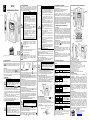
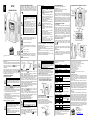
ITA
HT12
MANUALE D’USO
1. PRECAUZIONI E MISURE DI SICUREZZA
Lo strumento è stato progettato in conformità alla direttiva
IEC/EN61010-1, relativa agli strumenti di misura elettronici. Per la
Sua sicurezza e per evitare di danneggiare lo strumento, La
preghiamo di seguire le procedure descritte nel presente manuale e
di leggere con particolare attenzione tutte le note precedute dal
simbolo
ATTENZIONE
Non effettuare misure in ambienti umidi
Non effettuare misure in presenza di gas o
materiali esplosivi, combustibili o in ambienti
polverosi
Evitare contatti con il circuito in esame se non
si stanno effettuando misure
Evitare contatti con parti metalliche esposte,
con terminali di misura inutilizzati, circuiti, ecc
Non effettuare alcuna misura qualora si
riscontrino anomalie nello strumento come,
deformazioni, rotture, fuoriuscite di sostanze,
assenza di visualizzazione sul display, ecc
Prestare particolare attenzione quando si
effettuano misure di tensioni superiori a 20V in
quanto è presente il rischio di shock elettrici
Nel presente manuale e sullo strumento sono utilizzati i seguenti
simboli:
Attenzione: attenersi alle istruzioni riportate nel
manuale; un uso improprio potrebbe causare danni
allo strumento o ai suoi componenti.
Strumento con doppio isolamento
Lo strumento può pinzare cavi non isolati in tensione
corrispondenti alla categoria di misura indicata su di
esso
Tensione o Corrente AC
Tensione o Corrente DC
Copyright HT ITALIA 2013
Versione IT 1.02 - 15/02/2013
ATTENZIONE: il simbolo riportato sullo strumento
indica che l'apparecchiatura, i suoi accessori e le
batterie devono essere raccolti separatamente e
trattati in modo corretto
5. DESCRIZIONE DEI TASTI FUNZIONE
Non eseguire misure su circuiti con tensione
maggiore di 600V AC/DC tra le fasi o maggiore di
300V AC/DC tra fase e terra al fine di evitare shock
elettrici e possibili danni allo strumento
Non eseguire misure con puntali di misura collegati
all’impianto
Non applicare forti vibrazioni al sensore a pinza
durante la misura e mantenere le dita al di sotto
della barriera di protezione del sensore
Questo strumento è stato progettato per un
utilizzo in un ambiente con livello di
inquinamento 2
Può essere utilizzato per misure di TENSIONE
e CORRENTE su installazioni in CAT III 300V
e CAT II 600V
Solo i puntali forniti a corredo dello strumento
garantiscono gli standard di sicurezza. Essi
devono essere in buone condizioni e sostituiti,
se necessario, con modelli identici
Non effettuare misure su circuiti che superano i
limiti di tensione specificati
Non effettuare misure in condizione ambientali
al di fuori delle limitazioni indicate nel § 8
Controllare se le batterie sono inserite
correttamente
Prima di collegare i puntali al circuito in esame,
controllare che il selettore sia posizionato
correttamente
Controllare che il display LCD e il selettore
indichino la stessa funzione
Prima di azionare il selettore, scollegare i
puntali di misura dal circuito in esame
Quando lo strumento è connesso al circuito in
esame non toccare mai un qualunque
terminale inutilizzato
Se, durante una misura, il valore o il segno
della grandezza in esame rimangono costanti
controllare se è attivata la funzione HOLD
ATTENZIONE
Prima di effettuare qualunque misura di resistenza
accertarsi che il circuito in esame non sia alimentato e
che eventuali condensatori presenti siano scarichi
1. Selezionare la posizione
/ . I simboli “M ” e “O.L” sono
presenti a display. Premere il tasto RH per la selezione del
campo di misura manuale (vedere § 5.1)
2. Posizionare i puntali nei punti desiderati del circuito in esame. Il
valore della resistenza è visualizzato a display
3. Il test di continuità è sempre attivo e il cicalino suona per valori di
resistenza <30 . In modo Manuale Il simbolo “ ” appare solo
nella portata 340
4. DESCRIZIONE DELLO STRUMENTO E DEL DISPLAY
Lo strumento HT12 esegue le seguenti misure:
Tensione DC e AC
Corrente DC e AC tramite sonda a pinza integrata
Resistenza e Test Continuità
Frequenza corrente e tensione
Ciascuna di queste funzioni può essere selezionata tramite un
selettore a 7 posizioni. Sono inoltre presenti i tasti funzione DH e
RH (vedere § 5.1 e § 5.2) e una barra grafica analogica. La
grandezza selezionata appare sul display LCD con indicazioni
dell’unità di misura e delle funzioni abilitate. Lo strumento è
inoltre dotato di un dispositivo di Auto Power OFF che provvede a
spegnere automaticamente lo strumento trascorsi 10 minuti
dall'ultima pressione dei tasti funzione o rotazione del selettore
3. PREPARAZIONE ALL’UTILIZZO
1.2 Definizione di categoria di sovratensione
In accordo alla norma IEC/EN61010-1 i circuiti sono suddivisi nelle
seguenti categorie di misura:
La CAT IV serve per le misure effettuate su una sorgente di
un’installazione a bassa tensione
La CAT III serve per le misure effettuate in installazioni all’interno
di edifici
La CAT II serve per le misure effettuate su circuiti collegati
direttamente all’installazione a bassa tensione
La CAT I serve per le misure effettuate su circuiti non collegati
direttamente alla RETE DI DISTRIBUZIONE
3.1 Controlli iniziali
Lo strumento, prima di essere spedito, è stato controllato dal
punto di vista elettrico e meccanico. Sono state prese tutte le
precauzioni possibili affinché lo strumento potesse essere
consegnato senza danni. Tuttavia si consiglia, comunque, di
controllare sommariamente lo strumento per accertare eventuali
danni subiti durante il trasporto. Se si dovessero riscontrare
anomalie contattare immediatamente lo spedizioniere. Si
consiglia inoltre di controllare che l’imballaggio contenga tutte le
parti indicate al § 8 In caso di discrepanze contattare il
rivenditore. Qualora fosse necessario restituire lo strumento, si
prega di seguire le istruzioni riportate al § 9
3.2 Alimentazione dello strumento
Lo strumento è alimentato tramite 2x1.5V batterie AAA LR03
fornite in dotazione. Quando la batteria è scarica appare il
simbolo "
". Per sostituire la batteria seguire le istruzioni
riportate al §7
3.3 Taratura
Lo strumento rispecchia le caratteristiche tecniche riportate nel
presente manuale. Le prestazioni dello strumento sono garantite
per un anno
3.4 Conservazione
Per garantire misure precise, dopo un lungo periodo di
immagazzinamento in condizioni ambientali estreme, attendere
che lo strumento ritorni alle condizioni normali (vedere le
specifiche ambientali elencate al § 8
6.4 Misura di Frequenza
8. SPECIFICHE TECNICHE
Non eseguire misure su circuiti con tensione
maggiore di 600V AC/DC tra le fasi o maggiore di
300V AC/DC tra fase e terra al fine di evitare shock
elettrici e possibili danni allo strumento
5.2 Tasto RH
Premere il tasto RH per attivare il cambio portata manuale sullo
strumento spegnendo la scritta "AUTO" e mostrando il simbolo “ ” a 6.2.1 Misura di Corrente DC
display. Premere il tasto RH per oltre 1 secondo o ruotare il selettore
1. Selezionare la posizione
. I simboli “DC” e “AUTO” sono
per uscire dal modo manuale e ripristinare il modo Autorange
presenti a display. Premere il tasto RH per la selezione del
automaticamente attivo ad ogni accensione
campo di misura manuale (vedere § 5.1)
2. Eseguire l’azzeramento ruotando l’apposito regolatore
6. ESECUZIONE DELLE MISURE
presente sulla parte centrale del sensore a pinza. Il valore “0.0”
6.1 Misura di Tensione DC/AC
deve essere presente a display per eseguire misure corrette
ATTENZIONE
3. Inserire un conduttore nella fessura del sensore a pinza
La massima tensione AC/DC in ingresso è 600V. Non
collocandolo al centro delle due frecce indicatrici nella parte
misurare tensioni che eccedano i limiti indicati in
frontale della pinza (vedere Figura) e rispettando il verso della
questo manuale. Il superamento di tali limiti potrebbe
freccia presente nella parte laterale della pinza
causare shock elettrici all’utilizzatore e danni allo
4. Leggere il risultato della misura a display. La visualizzazione del
strumento
simbolo "-" sul display dello strumento indica che la corrente ha
verso opposto rispetto al collegamento eseguito
1. Selezionare la posizione
o . I simboli “DC” o “AC” e “AUTO”
sono presenti a display. Premere il tasto RH per la selezione del 6.2.2 Misura di Corrente AC
1. Selezionare la posizione
. I simboli “AC” e “AUTO” sono
campo di misura manuale (vedere § 5.2)
presenti a display. Premere il tasto RH per la selezione del
2. Posizionare il puntale rosso ed il puntale nero rispettivamente nei
campo di misura manuale (vedere § 5.1)
punti a potenziale (+) e (-) del circuito in esame (per tensione
2. Inserire un conduttore nella fessura del sensore a pinza
DC). Il valore della tensione è mostrato a display
collocandolo al centro delle due frecce indicatrici nella parte
3. Il messaggio "O.L" indica che il valore di tensione eccede il
frontale della pinza (vedere Figura) e rispettando il verso della
valore massimo misurabile
freccia presente nella parte laterale della pinza
4. Nella misura di tensione DC la visualizzazione del simbolo "-" sul
display dello strumento indica che la tensione ha verso opposto 3. Leggere il risultato della misura a display
4. Per l’uso della funzione Data HOLD vedere il § 5.1
rispetto al collegamento eseguito
6.3 Misura di Resistenza e Test Continuità
5. Per l’uso della funzione Data HOLD vedere il § 5.1
ATTENZIONE
2. DESCRIZIONE GENERALE
ATTENZIONE
ATTENZIONE
5.1 Tasto DH
La pressione del tasto DH attiva il mantenimento del valore della
grandezza visualizzata a display. Conseguentemente alla pressione
di tale tasto la scritta "H" e il simbolo “ ” appaiono a display.
Premere nuovamente il tasto DH per uscire dalla funzione
6.2 Misura di Corrente con sensore a pinza
1.1 Istruzioni preliminari
6.4.1 Misura di Frequenza della tensione
1. Selezionare la posizione Hz. Premere il tasto RH per la
selezione del campo di misura manuale (vedere § 5.1)
2. Posizionare i puntali nei punti desiderati del circuito in esame.
Il valore della frequenza (in kHz o MHz) è mostrato a display
6.4.2 Misura di Frequenza della corrente
1. Selezionare la posizione Hz. Premere il tasto RH per la
selezione del campo di misura manuale (vedere § 5.1)
2. Posizionare il conduttore al centro delle frecce del sensore a
pinza. Il valore (in kHz o MHz) è mostrato a display
NON COLLEGARE SIMULTANEAMENTE I PUNTALI DI
MISURA E IL SENSORE A PINZA ALL’IMPIANTO
Incertezza riferita a 23°C± 5°C, <75%RH
Corrente AC
Campo misura
Risoluzione
Incertezza
0.1A
0.0 60.0A
(2.0%lettura+5cifre) (50/60Hz)
Protezione da sovraccarichi: 72A AC/DC per 10s
Corrente DC
Campo misura
Risoluzione
Incertezza
0.1A
0.0 60.0A
(2.0%lettura+5cifre)
Protezione da sovraccarichi: 72A AC/DC per 10s
Tensione AC
Campo misura
Risoluzione
Incertezza
0.000 3.400V
0.001V
0.01V
0.00 34.00V
(1.5%lettura+5cifre) (50-400Hz)
0.1V
0.0 340.0V
1V
0 600V
Impedenza di ingresso: 10M ; Prot. sovraccarichi: 720V AC/DC per 10s
Tensione DC
Campo misura
Risoluzione
Incertezza
0.001mV
0.000 340.0mV
0.001V
0.000 3.400V
0.01V
0.00 34.00V
(1.5%lettura+4cifre)
0.1V
0.0 340.0V
1V
0 600V
Impedenza di ingresso: 10M ; Prot. sovraccarichi: 720V AC/DC per 10s
Resistenza e Test Continuità
7. SOSTITUZIONE BATTERIE
Quando sul display appare il simbolo "
" occorre sostituire le
batterie operando nel modo seguente:
1. Spegnere lo strumento con il tasto OFF
2. Rimuovere il guscio protettivo dallo strumento
3. Svitare la vite di fissaggio del vano batteria e rimuoverlo
4. Rimuovere le batterie e sostituirle con altre dello stesso tipo
5. Riposizionare il coperchio del vano batteria
Campo misura
0.0 340.0
0.000 3.400k
0.00 34.00k
0.0 340.0k
0.000 3.400M
0.00 34.00M
Risoluzione
0.1
0.001k
0.01k
0.1k
0.001M
0.01M
Incertezza
(1.0%lettura+3cifre)
Cicalino attivo per R<30 10
Solo nel campo 340
(5.0%lettura+5cifre)
(15.0%lettura+5cifre)
Frequenza
Tipo misura
Campo
Incertezza
Corrente
0 10kHz
(0.1%lettura+1cifra)
Tensione
0 300kHz
Corrente minima misurabile: 15A ; Tensione minima misurabile: 30V
Sicurezza: IEC/EN61010-1, IEC/EN61010-2-031, IEC/EN61010-2-032
Categoria di misura: CAT III 300V , CAT II 600V, Grado di inquinamento: 2
Isolamento: doppio isolamento
Conformità a direttiva 2004/108/CE (EMC) e 2006/95/CE (LVD)
Display: LCD, ¾ cifre, 3400 punti con bargraph
Frequenza di campionamento: circa 400ms (circa 20ms bargraph)
Indicazione fuori scala: simboli “O.L” o “-O.L” a display
Alimentazione: 2x1.5V batterie tipo AAA LR03 UM-4
Auto Power OFF: dopo 10 minuti di non utilizzo (non disattivabile)
Temperatura di riferimento: 23°C± 5°C; <75%RH
Temperatura di lavoro: 0 40°C ; <85%RH
Temperatura di conservazione: -20 60°C ; <85%RH
Max altitudine di utilizzo: 2000m
Max diametro conduttore pinzabile: 6mm
Dimensioni (LxLaxH): 128x87x24mm
Peso (con batterie): 210g
Accessori in dotazione: batterie, manuale d’uso, cartolina di garanzia
9. ASSISTENZA
9.1 Condizioni di garanzia
Questo strumento è garantito contro ogni difetto di materiale e
fabbricazione, in conformità con le condizioni generali di vendita.
Durante il periodo di garanzia, le parti difettose possono essere
sostituite, ma il costruttore si riserva il diritto di riparare ovvero
sostituire il prodotto.
Qualora lo strumento debba essere restituito al servizio post vendita o ad un rivenditore, il trasporto è a carico del Cliente. La
spedizione dovrà, in ogni caso, essere preventivamente concordata.
Allegata alla spedizione deve essere sempre inserita una nota
esplicativa circa le motivazioni dell’invio dello strumento. Per la
spedizione utilizzare solo l’imballo originale; ogni danno causato
dall’utilizzo di imballaggi non originali verrà addebitato al Cliente. Il
costruttore declina ogni responsabilità per danni causati a persone o
oggetti
9.2 Assistenza
Se lo strumento non funziona correttamente, prima di contattare il
Servizio di Assistenza, controllare lo stato della batteria e dei cavi e
sostituirli se necessario. Se lo strumento continua a manifestare
malfunzionamenti controllare se la procedura di utilizzo dello stesso
è conforme a quanto indicato nel presente manuale. Qualora lo
strumento debba essere restituito al servizio post - vendita o ad un
rivenditore, il trasporto è a carico del Cliente. La spedizione dovrà, in
ogni caso, essere preventivamente concordata. Allegata alla
spedizione deve essere sempre inserita una nota esplicativa circa le
motivazioni dell’invio dello strumento. Per la spedizione utilizzare
solo l’imballaggio originale; ogni danno causato dall’utilizzo di
imballaggi non originali verrà addebitato al Cliente.
HT ITALIA SRL
Via della Boaria, 40
48018 – Faenza (RA) – ITALY
Tel: +39-0546-621002
Fax: +39-0546-621144
Web: www.ht-instruments.com
Email: [email protected]
ENG
HT12
USER MANUAL
1. PRECAUTIONS AND SAFETY MEASUREMENTS
This instrument complies with safety Standard IEC/EN61010-1
related to electronic measuring instruments. For your own safety and
to avoid damaging the instrument follow the procedures described in
this instruction manual and read carefully all notes preceded by this
symbol
CAUTION
Avoid measuring in humid or wet places
Avoid measuring in rooms where explosive
gas, combustible gas, steam or excessive dust
is present
Keep you insulated from the object under test
Do not touch exposed metal parts such as test
lead ends, sockets, fixing objects, circuits etc.
Avoid doing that if you notice anomalous
conditions such as breakages, deformations,
fractures, leakages of battery fluid, blind display
etc.
Be careful when measuring voltages exceeding
20V to avoid risks of electrical shock
The following symbols are used in user manual and on the meter:
CAUTION - refer to the instruction manual - an
improper use may damage the instrument or its
components
Double insulated meter
The instrument can clamp not insulated live cables
corresponding to the measurement category
indicated on them
AC voltage or current
DC voltage or current
CAUTION: this symbol indicates that equipment, its
accessories and battery shall be subject to a
separate collection and correct disposal
Copyright HT ITALIA 2013
Release EN 1.02 - 15/02/2013
This instrument has been designed for use in
environments with pollution degree 2
It can be used for VOLTAGE and CURRENT
measurements on installations with overvoltage
category CAT III 300V and CAT II 600V
Only the leads supplied with the instrument
guarantee compliance with the safety
standards in force. They must be under good
conditions and, if necessary, replaced with
identical ones
Do not test or connect to any circuit exceeding
the specified overload protection
Do
not
effect
measurements
under
environmental conditions exceeding the limits
indicated in § 8
Make sure that batteries are properly installed
Before connecting the test probes to the
installation, make sure that the function
selector is positioned on the required
measurement
Make sure that LCD and function selector
indicate the same function
When changing the range, first disconnect the
test leads from the circuit under test in order to
avoid any accident
When the instrument is connected to
measuring circuits never touch any unused
terminal
If during measurement the displayed values
remain constant check whether the HOLD
function is active
1.2 Measuring overvoltage category definitions
According to the IEC/EN61010-1 guidelines the circuits are divided
into the following measurement categories:
CAT IV is for measurements performed at the source of the lowvoltage installation
CAT III is for measurements performed in the building installation
CAT II is for measurements performed on circuits directly
connected to the low voltage installation
CAT I is for measurements performed on circuits not directly
connected to MAINS
5.2 RH key
By pushing RH key, the manual mode is activated, the “AUTO”
symbol disappears and the symbol “ ” is displayed. To quit this
function keep RH key pressed for at least 1 second or rotate the 6.2.1 DC Current measurement
selector into another position. The Autorange mode is automatically
1. Rotate the selector on position. The “DC” and “AUTO” symbols
active whenever you switch on the meter
are displayed. Press RH key for the selection of manual range
(see § 5.2)
6. HOW TO PERFORM THE MEASUREMENTS
2. Perform zeroing operation turning the adjust knob which is
6.1 DC/AC Voltage measurement
present on the central part of the clamp sensor. The “0.0” value
CAUTION
should be displayed to perform correct measurements
Maximum input for AC/DC voltage measurements is
3. Put the conductor in the fork of clamp sensor at the centre of the
600V. Do not take any voltage measurement
arrows keys which are present in the frontal side (see picture)
exceeding this limit in order not to risk electrical shock
and respect the current direction as indicated by the arrow key
or damaging the meter
which is present on the meter sideways
1. Rotate the selector on
or position. The “DC” or “AC” and 4. The current value is displayed. The symbol "-" on the instrument
display indicates that the current has opposite direction
“AUTO” symbols are shown at display. Press RH key for the
compared to the previous connection
selection of manual range (see § 5.2)
2. Connect the red and black test leads to the positive and negative 6.2.2 AC Current measurement
position. The “AC” and “AUTO”
poles of the circuit under test respectively (for DC voltage). The 1. Rotate the selector onto
symbols are displayed. Press RH key for the selection of manual
voltage value is displayed
range (see § 5.2)
3. If the message "O.L" is displayed the maximum voltage value
2. Put the conductor in the fork of clamp sensor at the centre of the
was exceeded
arrows keys which are present in the frontal side (see picture)
4. On DC voltage measurement the symbol "-" on the instrument
and respect the current direction as indicated by the arrow key
display indicates that voltage has opposite direction compared to
which is present on the meter sideways
the previous connections
3. The current value is displayed
5. For Data HOLD feature see § 5.1
4. For Data HOLD feature see § 5.1
6.2 Current measurement with fork sensor clamp
6.3 Resistance and Continuity test measurements
CAUTION
Before taking resistance measurements on circuit
remove power from the circuit under test and
discharge all capacitors
1. Rotate the selector onto
/
position. The “M ” and “O.L”
symbols are displayed. Press RH key for the selection of manual
range (see § 5.2)
2. Connect the test leads to the circuit under test. The resistance
value is displayed
3. The continuity test is always active and the buzzer sounds when
resistance values are lower than 30 . In Manual mode the “ ”
symbol is displayed only in the 340 range
4. INSTRUMENT AND DISPLAY DESCRIPTION
HT12 performs the following measurements:
DC and AC voltage
DC and AC current by using integrated sensor fork clamp
Resistance and continuity test
Voltage and current frequency
All selectable by means of a 7-position function selector. Function
keys DH and RH in addition to an analogical bargraph are also
available (see § 5.1 and § 5.2). The selected quantity is displayed
with indication of measuring unit and active functions. The
instrument is provided with an Auto Power Off function consisting
in an automatic switching off 10 minutes after last pressure on
keys or rotation of selector. To resume normal operation, switch
on the instrument again
3. PREPARATION FOR USE
3.1 Initial checks
This instrument was checked both mechanically and electrically
prior to shipment. All possible cares and precautions were taken
to let you receive the instrument under perfect conditions.
Notwithstanding we suggest you to check it rapidly (any damage
may have occurred during transport – if so please contact the
local distributor from whom you bought the item). Make sure that
all standard accessories mentioned in § 8 are included. Should
you have to return back the instrument for any reason please
follow the instructions mentioned in § 9
3.2 Supply voltage
The instrument is powered by 2x1.5V batteries AAA LR03
included in the packaging. When batteries are low the symbol
"
" is displayed. To replace/insert batteries follow the
instructions indicated in § 7
3.3 Calibration
The instrument complies with the technical specifications
contained in this manual and such compliance is guaranteed for
12 months
3.4 Storage
After a period of storage under extreme environmental conditions
exceeding the limits mentioned in § 8 let the instrument resume
normal operating conditions before using it
8. TECHNICAL SPECIFICATIONS
CAUTION
5.1 DH key
By pressing DH key the measured value is hold on the display where
the symbols "H" and “ ” appear. Pressing again DH to disable this
function and resume normal operation
CAUTION
2. GENERAL DESCRIPTION
CAUTION
6.4 Frequency measurement
5. FUNCTION KEYS DESCRIPTION
Do not perform measurements on circuits with a
voltage exceeding 600V AC/DC between phases or
exceeding 300V AC/DC between phase and ground
to avoid possible shock hazard
Do not perform measurements with test leads
connected to the circuit under test
Do not apply strong vibrations to the clamp sensor
and keep the fingers behind the protective bar
during measurements
1.1 Preliminary instructions
Do not perform measurements on circuits with a
voltage exceeding 600V AC/DC between phases or
exceeding 300V AC/DC between phase and ground
to avoid possible shock hazard
6.4.1 Voltage frequency measurement
1. Rotate the selector on Hz position. Press RH key for the
selection of manual range (see § 5.2)
2. Connect the test leads to the circuit under test. The frequency
value (in kHz or MHz) is displayed
6.4.2 Current frequency measurement
1. Rotate the selector on Hz position. Press RH key for the
selection of manual range (see § 5.2)
2. Put the conductor in the fork of clamp sensor at the centre of
the arrows keys. The value (in kHz or MHz) is displayed
DO NOT CONNECT SIMULTANEOUSLY THE TEST LEADS
AND THE CLAMP SENSOR TO THE INSTALLATION
The accuracy is referred to 23°C± 5°C, <75%RH
AC Current
Meas. Range
Resolution
0.1A
0.0 60.0A
Overload protection: 72A AC/DC for 10s
Accuracy
(2.0%rd+5dgt) (50/60Hz)
DC Current
Meas. Range
Resolution
0.1A
0.0 60.0A
Overload protection: 72A AC/DC for 10s
Accuracy
(2.0%rdg+5dgt)
9. SERVICE
AC Voltage
Meas. Range
Resolution
Accuracy
0.000 3.400V
0.001V
0.01V
0.00 34.00V
(1.5%rdg+5dgt) (50-400Hz)
0.1V
0.0 340.0V
1V
0 600V
Input impedance: 10M ; Overload protection: 720V AC/DC for 10s
DC Voltage
Meas. Range
Resolution
Accuracy
0.001mV
0.000 340.0mV
0.001V
0.000 3.400V
0.01V
0.00 34.00V
(1.5%rdg+4dgt)
0.1V
0.0 340.0V
1V
0 600V
Input impedance: 10M ; Overload protection: 720V AC/DC for 10s
Resistance and Continuity test
7. BATTERY REPLACEMENT
When the "
" low battery indication is displayed the batteries
must be replaced as follows:
1. Switch OFF the meter
2. Remove the protection holster from the instrument
3. Remove the fixing screw and the battery compartment cover
4. Remove batteries and replace with new ones of the same type
5. Replace battery compartment cover and holster
Meas. Range
0.0 340.0
0.000 3.400k
0.00 34.00k
0.0 340.0k
0.000 3.400M
0.00 34.00M
Resolution
0.1
0.001k
0.01k
0.1k
0.001M
0.01M
Sampling rate: approx 400ms (approx 20ms bargraph)
Over range indication: “O.L” or “-O.L” symbols at display
Power supply: 2x1.5V alkaline batteries type AAA LR03 UM-4
Auto Power OFF: after 10 minutes of idleness (not disable)
Reference temperature/humidity: 23°C± 5°C (73°F ± 41°F) ; <75%RH
Working temperature/humidity: 0 40°C (32°F 104°F) ; <85%RH
Storage temperature/humidity: -20 60°C (-4°F 140°F) ; <85%RH
Max height of use: 2000m (6562ft)
Max diameter conductor : 6mm (0.2in)
Dimensions (LxWxH): 128x87x24mm (5x3x1in)
Weight (with batteries): 210g (7ounces)
Included accessories: batteries, user manual
Accuracy
(1.0%rdg+3dgt)
Buzzer active for R<30 10
Only on 340 range
(5.0%rdg+5dgt)
(15.0%rdg+5dgt)
Frequency
Meas. Type
Meas. Range
Accuracy
Current
0 10kHz
(0.1%rdg+1dgt)
Voltage
0 300kHz
Current sensitivity: 15A ; Voltage sensitivity: 30V
Safety: IEC/EN61010-1, IEC/EN61010-2-031, IEC/EN61010-2-032
Measurement category: CAT III 300V , CAT II 600V, Pollution degree: 2
Insulation: double insulation
Compliance with 2004/108/CE (EMC) and 2006/95/CE (LVD) Directives
Display: LCD, ¾ dgt, 3400 points with bargraph
9.1 Warranty conditions
This instrument is guaranteed for one year against material or
production defects, in accordance with our general sales conditions.
During the warranty period the manufacturer reserves the right to
decide either to repair or replace the product. Should you need for
any reason to return back the instrument for repair or replacement
take prior agreements with the local distributor from whom you
bought it.
Do not forget to enclose a report describing the reasons for returning
(detected fault). Use only original packaging. Any damage occurred
in transit due to not original packaging will be charged anyhow to the
customer
9.2 Service
Should the instrument not work properly, make sure that batteries are
correctly installed and working before contacting your distributor, also
check the test leads and replace them if necessary.
Should you need for any reason to return back the instrument for
repair or replacement take prior agreements with the local distributor
from whom you bought it.
Do not forget to enclose a report describing the reasons for returning
(detected fault). Use only original packaging. Any damage occurred
in transit due to not original packaging will be charged anyhow to the
customer. The manufacturer will not be responsible for any damage
to persons or things.
HT ITALIA SRL
Via della Boaria, 40
48018 – Faenza (RA) – ITALY
Tel: +39-0546-621002
Fax: +39-0546-621144
Web: www.ht-instruments.com
Email: [email protected]
ESP
HT12
MANUAL DE INSTRUCCIONES
1. PRECAUCIONES Y MEDIDAS DE SEGURIDAD
El instrumento ha sido proyectado conforme a la directiva
IEC/EN61010-1, relativa a los instrumentos de medida electrónicos.
Para su seguridad y para evitar dañar el instrumento, le rogamos
que siga los procedimientos descritos en el presente manual y
preste particular atención a todas las notas precedidas por el
símbolo
ATENCIÓN
No efectúe medidas en entornos húmedos
No efectúe medidas en presencia de gas o
materiales explosivos, combustibles o en
ambientes con polvo
Evite el contacto con el circuito en examen si
no se están efectuando medidas
Evite contactos con partes metálicas
expuestas, con terminales de medidas
inutilizados, circuitos, etc
No efectúe ninguna medida si encuentra
alguna anomalía en el instrumento como
deformaciones,
roturas,
pérdidas
de
sustancias, ausencia de visualizador, etc
Preste particular atención cuando se efectúen
medidas de tensión superiores a 20V ya que
existe el riesgo del choque eléctrico
En el presente manual y en el instrumento se utilizan los siguientes
símbolos:
Atención: aténgase a las instrucciones indicadas en
el manual; un uso impropio puede causar daños al
instrumento o a sus componentes.
Instrumento con doble aislamiento
El instrumento puede pinzar los conductores activos
no aislados correspondientes en la categoría de
medida indicada sobre el mismo
Tensión o Corriente CA
Tensión o Corriente CC
Copyright HT ITALIA 2013
Versión ES 1.02 - 15/02/2013
ATENCIÓN: el símbolo adjunto indica que el
instrumento pila y sus accesorios deben ser
reciclados separadamente y tratados de modo
correcto
6.1 Medida de Tensión CC/CA
ATENCIÓN
La máxima tensión CC/CA de entrada es 600V. No
mida tensiones que superen los límites indicados en
este manual. Si se superan estos límites de tensión
puede causar el choque eléctrico al usuario y daños
al instrumento
1. Seleccione la posición
o
. Los símbolos “DC” o “AC” y
“AUTO” aparecen en el visualizador. Pulse la tecla RH para
activar el cambio de escala manual (ver § 5.2)
2. Posicione la punta roja y la punta negra respectivamente en los
puntos con potencial (+) y (-) en el circuito en examen (para
tensión CC). El valor de la tensión aparecen en el el visualizador
3. El mensaje "O.L" indica que el valor de la tensión es superior al
fondo de escala
4. Para la medida de tensión CC el símbolo “-“ en el visualizador
indica que el valor de la tensión está invertida respecto a la
conexión anterior
5. Para el uso de la función HOLD ver el § 5.1
6.2 Medida de Corriente con sensor integrado
ATENCIÓN
Para evitar el riesgo de sufrir un choque eléctrico no
realice nunca medida en circutos con más de 600V
CA/CC entre cables y 300V CA/CC entre conductor
y tierra
No realice mediciones con los cables de prueba
conectados en el circuito en prueba
Cuando utilice el sensor tenga la precaución de que
no reciba golpes ni vibraciones excesivas y no
efectúe mediciones con la mano después de la
barrera de seguridad del paramanos
Este instrumento ha sido proyectado para su
uso en entornos con nivel de polución 2
Puede ser utilizado para medidas de TENSIÓN
y CORRIENTE en instalaciones con CAT III
300V y CAT II 600V
Sólo las puntas de prueba incluidas en el
embalaje del instrumento garantizan las
normas de seguridad. Por lo tanto deben estar
en buenas condiciones e sustituirlas si fuese
necesario con modelos idénticos
No efectúe medidas en circuitos que superen
los límites de corriente y tensión especificados
No
efectúe
medidas
en
condiciones
ambientales fuera de las limitaciones indicadas
en el § 8
Controle que las pilas esté instaladas
correctamente
Antes de conectar las puntas al circuito en
examen, controle que el conmutador esté
posicionado correctamente
Controle que el visualizador LCD y el
conmutador indiquen la misma función
Antes de accionar el conmutador, desconecte
las puntas de prueba del circuito en examen
Cuando el instrumento está conectado al
circuito en examen no toque nunca ningún
terminal inutilizado
Si, durante una medida, el valor o el signo de
la magnitud en examen permanece constante
controle si está activada la función HOLD
1.2 Definición de categoría de sobretensión
En acuerdo con la norma IEC/EN61010-1 los circuitos están
subdivididos en las siguientes categorías de medida:
La CAT IV sirve para las medidas efectuadas sobre una fuente
de una instalación de baja tensión
La CAT III sirve para las medidas efectuadas en instalaciones
interiores de edificios
La CAT II sirve para las medidas efectuadas sobre circuitos
conectados directamente a las instalaciones de baja tensión
La CAT I sirve para las medidas efectuadas sobre circuitos no
conectados directamente a la RED DE DISTRIBUCIÓN
Para evitar el riesgo de sufrir un choque eléctrico no
realice nunca medida en circutos con más de 600V
CA/CC entre cables y 300V CA/CC entre conductor y
tierra
6.2.1 Medida de Corriente CC
1. Seleccione la posición
.
. Los símbolos “DC” y “AUTO”
aparecen en el visualizador. Pulse la tecla RH para activar el
cambio de escala manual (ver § 5.2)
2. Gire al botón de ajuste a Cero presente sobre el sensor para
ajustar la lectura del visualizador a cero. El valor “0.0” deben
estar visualizado para correcte medidas
3. Inserte en cable en el centro de las flechas marcadas en el
sensor integrado (ver Figura) y observando la dirección de la
flecha en el lado de sensor
4. El valor de la corriente será visualizado. El símbolo “-“ en el
visualizador indica que la dirección de la corriente está invertida
respecto a la conexión anterior
6.2.2 Medida de Corriente CA
1. Seleccione la posición . Los símbolos “AC” y “AUTO” aparecen
en el visualizador. Pulse la tecla RH para activar el cambio de
escala manual (ver § 5.2)
2. Inserte en cable en el centro de las flechas marcadas en el
sensor integrado (ver Figura) y observando la dirección de la
flecha en el lado de sensor
3. El valor de la corriente será visualizado
4. Para el uso de la función HOLD ver el § 5.1
6.3 Medida de Resistencia y Prueba de Continuidad
ATENCIÓN
Antes de realizar cualquier medida en un circuito de
resistencia, desconecte la alimentación del circuito y
asegúrese
que
los
condensadores
estén
descargados
1. Seleccione la posición
/ . Los símbolos “M ” y “O.L”
aparecen en el visualizador. Pulse la tecla RH para activar el
cambio de escala manual (ver § 5.2)
2. Inserte las dos puntas de prueba en el punto deseado del
circuito, luego el instrumento muestra el resultado
3. La prueba de continuidad es siempre activa y el zumbador emite
una señal acústica cuando el valor de la resistencia medida es
inferior a 30 . En modo Manual el símbolo “ ” aparece sólo en
el rango 340
2. DESCRIPCIÓN GENERAL
4. DESCRIPCIÓN DEL INSTRUMENTO Y VISUALIZADOR
El instrumento HT12 puede efectuar las siguientes medidas:
Tensión CC y CA
Corriente CC y CA a través de sensor integrado
Resistencia y Prueba Continuidad
Frecuencia de corriente y tensión
Cada unos de estos parámetros pueden ser seleccionados
mediante el selector rotativo de 7 posiciones. Existen las teclas
función DH y RH (ver el § 5.1 y § 5.2) y barra gráfica. El
parámetro seleccionado aparece en el visualizador con
indicaciones de la unidad de medida y de las funciones puestas
en marcha. El instrumento posee un dispositivo de autoapagado
que apaga automáticamente el instrumento transcurridos 10
minutos desde la última vez que se presione una tecla o se haga
rotar el selector.
3. PREPARACIÓN PARA EL USO
3.1 Controles iniciales
El instrumento, antes de ser enviado, ha sido controlado desde el
punto de vista eléctrico y mecánico. Han sido tomadas todas las
precauciones posibles con el fin que el instrumento pueda ser
enviado sin ningún daño. Por lo tanto aconsejamos controlar
exhaustivamente el instrumento para encontrar eventuales daños
producidos durante el transporte. Si se encontrase cualquier
anomalía contacte inmediatamente con el transportista. Por otra
parte le aconsejamos que controle que el embalaje contenga
todas las piezas indicadas en el § 8 y en el caso de que exista
cualquier discrepancia contacte con el distribuidor. Si por
cualquier causa fuese necesario sustituir el instrumento, se ruega
seguir las instrucciones indicadas en el § 9
3.2 Alimentación del instrumento
El instrumento se alimenta mediante 2x1.5V pilas modelo AAA
LR03 incluidas en el embalaje. Cuando la pila está descargada
aparece el símbolo "
". Para sustituir la pila siga las
instrucciones reflejadas en el § 7
3.3 Calibrado
El instrumento respeta las características técnicas reflejadas en
este manual. Las prestaciones del instrumento están
garantizadas durante un año
3.4 Almacenamiento
Para garantizar medidas precisas, después de un largo período
de almacenamiento en condiciones ambientales extremas,
espere a que el instrumento esté en condiciones normales antes
de realizar cualquier medida (vea las especificaciones
ambientales listadas en el § 8
8. ESPECIFICACIONE TECNICAS
ATENCIÓN
5.1 Tecla DH
Pulsando la tecla DH activamos la congelación del valor leido en el
visualizador. Aparecerá en pantalla el mensaje "H” y el símbolo “ ” .
Esta modalidad puede ser desactivada si pulsamos nuevamente la
tecla DH
6. INSTRUCCIONES OPERATIVAS
ATENCIÓN
6.4 Medida de Frecuencia
5. DESCRIPCIÓN DE LAS TECLAS FUNCIÓN
5.2 Tecla RH
Pulse la tecla RH para activar la modalidad manual y desactivar el
símbolo "AUTO" presente en el visualizador y activar el simbolo
“ ”.Pulse la tecla RH durante más de 1 segundo para salir del
modo manual y volver al modo Autorango
1.1 Instrucciones preliminares
6.4.1 Medida de Frecuencia de la tensión
1. Seleccione la posición Hz. Pulse la tecla RH para activar el
cambio de escala manual (ver § 5.2)
2. Inserte las dos puntas de prueba en el punto deseado del
circuito, luego el instrumento muestra el resultado (en kHz o
MHz)
6.4.2 Medida de Frecuencia de la corriente
1. Seleccione la posición Hz. Pulse la tecla RH para activar el
cambio de escala manual (ver § 5.2)
2. Inserte en cable en el centro de las flechas marcadas en el
sensor integrado. El valor (en kHz o MHz) es visualizado
NO CONECTE SIMULTÁNEAMENTE EL SENSOR INTEGRADO
Y LOS CABLES DE PRUEBA EN EL CIRCUITO EN MEDIDA
La incertidumbre es relacionada a 23°C± 5°C, <75%RH
Corriente CA
Campo medida
Resolución
Incertidumbre
0.1A
0.0 60.0A
(2.0%lectura+5dgt) (50/60Hz)
Protección contra sobrecarga: 72A CA/CC para 10s
Corriente CC
Campo medida
Resolución
Incertidumbre
0.1A
0.0 60.0A
(2.0%lectura+5dgt)
Protección contra sobrecarga: 72A CA/CC para 10s
Tensión CA
Campo medida
Resolución
Incertidumbre
0.000 3.400V
0.001V
0.01V
0.00 34.00V
(1.5%lectura+5dgt) (50-400Hz)
0.1V
0.0 340.0V
1V
0 600V
Impedancia de entrada: 10M ; Prot. sobrecarga: 720V CA/CC para 10s
Tensión CC
Campo medida
Resolución
Incertidumbre
0.001mV
0.000 340.0mV
0.001V
0.000 3.400V
0.01V
0.00 34.00V
(1.5%lectura +4dgt)
0.1V
0.0 340.0V
1V
0 600V
Impedancia de entrada: 10M ; Prot. sobrecarga: 720V CA/CC para 10s
Resistencia y Prueba de Continuidad
7. SUSTITUCIÓN DE LAS PILAS
Cuando sobre el visualizador LCD aparece el símbolo "
" es
necesario sustituir las pilas como sigue:
1. Apague el instrumento con la tecla OFF
2. Quite el protector del instrumento
3. Quite el tornillo de fijación de la tapa de pilas
4. Desconecte las pilas y inserte nueva pilas del mismo tipo
5. Vuelva a poner la parte inferior e inserte el protector
Campo medida
0.0 340.0
0.000 3.400k
0.00 34.00k
0.0 340.0k
0.000 3.400M
0.00 34.00M
Resolución
0.1
0.001k
0.01k
0.1k
0.001M
0.01M
Incertidumbre
(1.0%lectura +3dgt)
Zumbador activo para
R<30 10
Sólo en el rango 340
(5.0%lectura+5dgt)
(15.0%lectura+5dgt)
Frecuencia
Tipo medida
Campo
Incertidumbre
Corriente
0 10kHz
(0.1%lectura+1dgt)
Tensión
0 300kHz
Corriente mínima en medida: 15A ; Tensión mínima en medida: 30V
Seguridad: IEC/EN61010-1, IEC/EN61010-2-031, IEC/EN61010-2-032
Categoria de medida: CAT III 300V , CAT II 600V, Nivel de Polución: 2
Aislamiento: doble aislamiento
Conformidad en las Directivas 2004/108/CE (EMC) y 2006/95/CE (LVD)
Visualizador: ¾ LCD, 3400 puntos con barra grafica
Frecuencia de muestreo: sobre 400ms (sobre 20ms barra grafica)
Indicación fuera escala: “OL” o bien “-OL” en el visualizador
Alimentación: 2x1.5V pilas tipo AAA LR03 UM-4
AutoApagado: después 10 minutos de no utilizar (no puede ser desactivado)
Temperatura/Humedad de referencia: 23°C± 5°C; <75%RH
Temperatura/Humedad de uso: 0 40°C ; <85%RH
Temperatura/Humedad de almacenaje: -20 60°C ; <85%RH
Altitud max de uso: 2000m
Diámetro max. conductor: 6mm
Dimensiones (LxLaxH): 128x87x24mm
Peso (incluidas las pilas): 210g
Accesorios en dotación: pilas, manual de instrucciones
9. ASISTENCIA
9.1 Condiciones de garantía
Este equipo está garantizado en cualquier material en su defecto de
fábrica, de acuerdo con las condiciones generales de venta. Durante
el período de garantía (un año), las piezas defectuosas serán
reemplazadas, el fabricante se reserva el derecho de decidir si
repara o canjea el producto. En el caso de tener que devolver el
instrumento al departamento post-venta o al distribuidor regional, el
envío del instrumento va a cargo del cliente. La entrega debe estar
acordada con el consignatario. Para el envío añada una nota en el
mismo paquete, lo más claro posible, las razones de reenvío y
usando el embalaje original. Cualquier daño causado por el
transporte sin usar el embalaje original será cargado al
consignatario. El fabricante no es responsable de los daños
causados a personas o cosas
9.2 Servicio
Si el equipo no funciona correctamente, antes de contactar con el
servicio técnico compruebe el estado de la pila, las puntas de
prueba, etc., y cámbielo si fuese necesario. Si el equipo no funciona
correctamente consulte el modo de funcionamiento descrito en este
manual. Cuando el instrumento deba enviarse al servicio postventa
o a un distribuidor, el transporte será a cargo del cliente. La
expedición deberá, en cada caso y previamente acordado y
aceptado el presupuesto por escrito. El envío, siempre debe
acompañarse de una nota explicativa lo más detallada posible de los
motivos del envío del instrumento. Utilice sólo el embalaje original,
todo daño causado por el uso de embalajes distintos al original será
a cargo del cliente. El constructor declina toda responsabilidad por
daños causados a personas u objetos.
HT ITALIA SRL
Via della Boaria, 40
48018 – Faenza (RA) – ITALY
Tel: +39-0546-621002
Fax: +39-0546-621144
Web: www.ht-instruments.com
Email: [email protected]
DEU
HT12
BEDIENUNGSANLEITUNG
1. SICHERHEITSHINWEISE
Dieses
Multimeter
entspricht
dem
Sicherheitsstandard
IEC/EN61010-1 für elektronische Messgeräte. Zu Ihrer eigenen
Sicherheit und um Schäden des Gerätes zu vermeiden, folgen sie
bitte den Hinweisen in dieser Bedienungsanleitung und lesen sie alle
Hinweise sorgfältig mit diesem Zeichen .
ACHTUNG
Vermeiden Sie Messungen in feuchter oder
nasser Umgebung, stellen Sie sicher, dass die
Umgebungsbedingungen
innerhalb
der
Gerätespezifikation liegen
Vermeiden Sie Messungen in der Nähe von
explosiven oder brennbaren Gasen oder dort
wo Gase gelagert werden, vermeiden Sie auch
Messungen in der Nähe von extremer Hitze
und Staub
Achten Sie darauf, dass Sie isoliert zum zu
testenden Objekt stehen
Berühren Sie keine frei liegenden Metallteile
wie Enden von Prüfleitungen, Steckdosen,
Befestigungen, Schaltkreise etc
Nehmen Sie keine Messungen vor, wenn Sie
anomale Bedingungen wie Bruchschäden,
Deformationen,
Sprünge,
Austritt
von
Batterieflüssigkeit, keine Anzeige am Display
etc. bemerken
Sind Sie besonders vorsichtig, wenn Sie
Spannungen über 20V messen, um sich nicht
des Risikos von Stromschlägen auszusetzen
Folgende Symbole kommen zur Anwendung:
VORSICHT: Beziehen Sie sich auf die nicht isoliert
Bedienungsanleitung.
Falscher
Gebrauch
beschädigt vielleicht das Messgerät oder seine
Bestandteile
Messgerät doppelt isoliert
Das Instrument kann spannungsführende Leiter mit
der angegebenen Kategorie messen.
AC Spannung oder Strom
Copyright HT ITALIA 2013
Ausführung DE 1.02 - 15/02/2013
DC Spannung oder Strom
ACHTUNG: Dieses Symbol zeigt an, dass das
Gerät, Batterie und die einzelnen Zubehörteile
fachgemäß und getrennt voneinander entsorgt
werden müssen
5. FUNKTIONTASTEN
5.2 RH-Taste
Durch Drücken der RH Taste, ist der manuelle Modus is aktiv, das
“AUTO” Symbol verschwindet und das Symbol “ ” erscheint im 6.2.1 DC Strommessung
Display. Um diese Funktion zu verlassen, halten Sie die RH Taste 1. Stellen Sie den Drehschalter in die Position . Das “DC” und
für min. 1 sec gedrückt oder wählen Sie eine andere Position des
“AUTO” Symbol wird angezeigt. Drücke die RH Taste für die
Wahlschalters. Der Autorange Modus ist automatisch aktiv nach
manuelle Bereichsauswahl (siehe § 5.2)
jedem Einschalten des Multimeters.
2. Führen Sie zunächst eine Nulljustage durch mit Hilfe des
Einstellrädchen im Griff der Gabelstromzange. Der Wert “0.0”
6. MESSUNGEN
sollte im Display angezeigt werden bevor eine DC Messung
6.1 DC/AC-Spannungsmessung
durchgeführt wird.
ACHTUNG
3. Positionieren Sie den Leiter in die Mitte des Gabelstromwandlers
Die max. Eingangsspannung ist DC/AC 600V.
und so tief in der Gabel wie möglich (siehe Pfeiltasten auf der
Versuchen Sie keine Spannung zu messen, die höher
Frontseite der Gabel) und beachten Sie die Stromflussrichtung
ist. Es besteht die Gefahr eines Stromschlages und
(Pfeilrichtung ist angegeben auf der schmalen Seite der Gabel
das Multimeter könnte zerstört werden
4. Der Stromwert wird angezeigt. Das Symbol "-" im Display gibt
eine Stromflussrichtung in entgegengesetzter Richtung an.
1. Stellen Sie den Drehschalter in die Position
oder . Das “DC”
6.2.2 AC Strommessung
oder “AC” und “AUTO” Symbol wird angezeigt. Drücke die RH
1. Stellen Sie den Drehschalter in die Position . Das “AC” und
Taste für die manuelle Bereichsauswahl (siehe § 5.2)
“AUTO” Symbol wird angezeigt. Drücke die RH Taste für die
2. Verbinden Sie nun die rote und die schwarze Messleitung mit
manuelle Bereichsauswahl (siehe § 5.2)
dem positiven und dem negativen Pol (für DC Spannung). Die
Spannungsgrösse wird automatisch erkannt und auf dem Display 2. Positionieren Sie den Leiter in die Mitte des Gabelstromwandlers
und so tief in der Gabel wie möglich (siehe Pfeiltasten auf der
angezeigt
Frontseite der Gabel) und beachten Sie die Stromflussrichtung
3. Wenn auf dem Display “O.L” erscheint, ist die gemessene
( Pfeilrichtung ist angegeben auf der schmalen Seite der Gabel)
Spannung höher als der verfügbare Messbereich
4. Bei der DC Spannungsmessung: Wenn auf dem Display “-“ 3. Der Stromwert wird angezeigt
4. Informationen über die HOLD-Funktionen erhalten Sie § 5.1
erscheint, wurden Plus- und Minuspol vertauscht
6.3 Widerstandsmessung & Durchgangsprüfung
5. Informationen über die HOLD-Funktionen erhalten Sie bei § 5.1
ACHTUNG
Die max. Eingangsspannung ist AC/DC 600V
(Phase/Phase) bzw. AC/DC 300V Phase gegen
Erde. Versuchen Sie keine Spannung zu messen,
die höher ist. Es besteht die Gefahr eines
Stromschlages.
Führen Sie keine Messungen durch wenn die
Messleitungen am Messkreis angeschlossen sind
Vermeiden Sie starke Vibrationen bei der
Gabelstromzange und halten Sie die Finger hinter
dem Schutzring während der Messung.
2. ALLGEMEINE BESCHREIBUNG
ACHTUNG
Dieses Gerät wurde für den Gebrauch in
Umgebungen der Schutzklasse 2 entworfen
Es kann zum Messen von Spannungen und
Strömen in Installationen der Kategorie CAT III
300V und der Kategorie CAT II 600V benutzt
werden
Nur die original Messleitungen die beim Gerät
dabei waren, entsprechen den gültigen
Sicherheitsstandards. Sie müssen in gutem
Zustand sein, und, falls nötig, durch identische
ersetzt werden
Testen Sie keinen, und schließen Sie das
Gerät auch an keinen Stromkreis an, der den
angegebenen Überlastungsschutz übersteigt
Nehmen Sie keinen Messungen vor, die die
angezeigten Grenzen in § 8 überschreiten
Überprüfen Sie den korrekten Einsatz der
Batterien
Vor dem Anschluss der Messleitungen in der
Installation überprüfen Sie, ob der richtige
Messbereich eingestellt ist
Überprüfen Sie ob das Display und der
Bereichswahlschalter die Selbe Funktion
anzeigen
Wenn Sie den zu messenden Bereich
ändernder, trennen Sie die Messleitungen
zuerst vom zu prüfenden Objekt, um jeden
Unfall zu vermeiden
Wenn das Gerät an die Messschaltungen
angeschlossen ist, berühren Sie nie eine
freiliegende Prüfleitung
Wenn Sie während der Messung einer Größe
oder eines Wertes, die Hold-Funktion drücken
bleibt die Anzeige erhalten, solange die HoldFunktion an ist
1.2 Uberspannungskategorien-definitionen
Die Norm IEC/EN61010-1 Messkategorien sind wie folgt eingeteilt:
CAT IV ist für Messgeräte, die an der Einspeisung der
Niederspannungsanlagen messen können
CAT III ist für Messgeräte, die in Gebäudeinstallationen messen
können
CAT II ist für Messgeräte, die Messungen an Geräten ausführen
die ein Netzanschlusskabel haben
CAT I ist für Messgeräte, die Messungen an Stromkreisen
ausführen, die nicht direkt mit dem Netz verbunden sind
6.4 Frequenzmessung
ACHTUNG
5.1 DH-Taste
Wenn die Data Hold Taste gedrückt wird, erscheint ein kleines „H“
und “ ” im Display und die Anzeige wird eingefroren. Um den Data
Hold Modus zu verlassen drücken Sie erneut die Data Hold Taste.
6.2 Strommessung mit Gabelstromwandler
1.1 Vorbereitung
ACHTUNG
Bevor Sie irgendwelche Widerstandsprüfungen
durchführen, entfernen Sie die Spannung am
Messkreis, der geprüft werden soll, und entladen Sie
alle Kondensatoren
1. Stellen Sie den Drehschalter in die Position / . Das “M ” und
“O.L” Symbol wird angezeigt. Drücke die RH Taste für die
manuelle Bereichsauswahl (siehe § 5.2)
2. Schliessen Sie die Messleitungen an das zu prüfende Objekt an.
Der Widerstandswert wird angezeigt.
3. Die Durchgangsprüfung ist immer aktiv und der Summer ertönt
bei Messwerten < 30 . Im manuellen Modus wird das “ ”
Symbol nur im Display beim 340 Messbereich erscheinen.
Die max. Eingangsspannung ist AC/DC 600V
(Phase/Phase) bzw. AC/DC 300V Phase gegen Erde.
Versuchen Sie keine Spannung zu messen, die höher
ist. Es besteht die Gefahr eines Stromschlages und
das Multimeter könnte zerstört werden
6.4.1 Frequenzmessung der Spannung
1. Stellen Sie den Drehschalter in die Hz Position. Drücke die RH
Taste für die manuelle Bereichsauswahl (siehe § 5.2).
2. Schliessen Sie die Messleitungen an das zu prüfende Objekt
an. Der Frequenzwert wird angezeigt (in kHz oder MHz).
6.4.2 Frequenzmessung des Stromes
1. Stellen Sie den Drehschalter in die Hz Position. Drücke die RH
Taste für die manuelle Bereichsauswahl (siehe § 5.2)
2. Positionieren
Sie
den
Leiter
in
die
Mitte
des
Gabelstromwandlers und so tief in der Gabel wie möglich. Der
Frequenzwert wird angezeigt (in kHz oder MHz).
Führen Sie niemals beide Messungen gleichzeitig durch !
4. INSTRUMENT UND ANZEIGE BESCHREIBUNG
Das Multimeter HT12 kann folgende Messungen ausführen:
DC und AC Spannung
DC und AC Strom über integrierten Gabelstromwandler
Widerstandmessung und Durchgangsprüfung
Frequenz bei Spannung und Strom
Jede dieser Funktionen kann mittels des 7-stelligen
Drehschalters gewählt werden. Es stehen noch weitere DH und
RH Funktionstasten (§ 5.1 und § 5.2), die eine Umschaltung der
Funktionen über das Display ermöglichen zur Verfügung. Die
gewählte Einstellung wird mit Hinweis auf die Maßeinheit und
aktive Funktionen angezeigt. Um Batteriekapazität zu sparen,
wird das Instrument 10 Minuten nach der letzten Benutzung einer
Funktionstaste oder der Veränderung der Drehschalterposition
ausgeschaltet. Die Wiedereinschaltung erfolgt durch die Wahl der
Drehschalterposition OFF und Wiedereinschalten
3. VORBEREITUNGEN FÜR DEN GEBRAUCH
3.1 Vorabprüfung
Dieses Multimeter wurde vor dem Versand mechanisch und
elektrisch überprüft. Es wurden alle möglichen Maßnahmen
getroffen, damit Sie das Gerät in perfektem Zustand erhalten.
Nichtsdestotrotz empfehlen wir eine schnelle Überprüfung (beim
Transport könnte es eventuell zu Beschädigungen gekommen
sein). – In diesem Fall wenden Sie sich bitte an den Händler, bei
dem Sie das Gerät erworben haben. Gehen Sie sicher, dass alle
in § 8. angeführten Standardzubehörteile vorhanden sind. Sollten
Sie das Gerät aus irgendeinem Grund zurückgeben müssen,
folgen Sie bitte den Anweisungen in § 9
3.2 Stromversorgung
Die Stromversorgung des Gerätes erfolgt durch eine 2x1.5V
Batterien AAA LR03 im Lieferumfang enthalten. Ist die Batterie
leer, erscheint dieses "
" Symbol im Display. Wechseln Sie die
Batterie wie im § 7 beschrieben
3.3 Kalibrierung
Das Gerät entspricht den technischen Spezifikationen, die in
dieser Gebrauchsanweisung angegeben sind, und diese
Entsprechung wird für ein Jahr ab Gebrauch garantiert. Eine
jährliche Neukalibrierung wird empfohlen
3.4 Lagerung
Nach einer Lagerung des Gerätes unter extremen
Umweltbedingungen, die den Zeitraum, der in § 8 angeführt ist,
überschreitet, warten Sie, bis das Gerät wieder normale
Messbedingungen erreicht hat, bevor Sie es benutzen
8. TECHNISCHE FUNKTIONEN
Die Genauigkeit ist bezogen auf 23°C± 5°C, <75%RH
AC Strom
Messbereich
Auflösung
0.1A
0.0 60.0A
Schutz vor Überlast: 72A AC/DC für 10s
Genauigkeit
(2.0%Anz+5dgt) (50/60Hz)
DC Strom
Messbereich
Auflösung
0.0 60.0A
0.1A
Schutz vor Überlast: 72A AC/DC für 10s
Genauigkeit
(2.0%Anz +5dgt)
9. SERVICE
AC Spannung
Messbereich
Auflösung
Genauigkeit
0.001V
0.000 3.400V
0.01V
0.00 34.00V
(1.5%Anz +5dgt) (50-400Hz)
0.0 340.0V
0.1V
0 600V
1V
Innenwiderstand: 10M ; Schutz vor Überlast: 720V AC/DC für 10s
DC Spannung
Messbereich
Auflösung
Genauigkeit
0.000 340.0mV
0.001mV
0.001V
0.000 3.400V
0.01V
0.00 34.00V
(1.5%Anz +4dgt)
0.1V
0.0 340.0V
1V
0 600V
Innenwiderstand: 10M ; Schutz vor Überlast: 720V AC/DC für 10s
Widerstandsmessung und Durchgangsprüfung
7. BATTERIEWECHSEL
Sind die Batterien leer, erscheint dieses Symbol "
" im Display.
Wechseln Sie dann die Batterien:
1. Schalten Sie das Messgerät AUS
2. Entfernen Sie das Schutzholster vom Messgerät
3. Entfernen Sie die Schraube und die Batterieabdeckung
4. Entfernen Sie die Batterien und ersetzen Sie diese durch neue
gleichen Typs
5. Befestigen Sie wieder die Batterieabdeckung und das Holster.
Messbereich
0.0
0.000
0.00
0.0
0.000
0.00
340.0
3.400k
34.00k
340.0k
3.400M
34.00M
Auflösung
0.1
0.001k
0.01k
0.1k
0.001M
0.01M
Messrate: ca. 400ms (ca. 20ms Bargraph)
Überlastanzeige: “O.L” oder “-O.L”
Batterietyp: 2x1.5V Alkaline Batterien AAA LR03 UM-4
Auto Power OFF: nach 10 min (nicht Deaktivierbar)
Referenzbedingung: 23°C± 5°C (73°F ± 41°F) ; <75%RH
Arbeitstemperatur/Zulässige relative: 0 40°C (32°F 104°F) ; <85%RH
Lagertemperatur /Lagerfeuchtigkeit: -20 60°C (-4°F 140°F) ; <85%RH
Für Innenbenutzung, max. Höhe: 2000m (6562ft)
Max Leiterdurchmesser: 6mm (0.2in)
Größe (LxWxH): 128x87x24mm (5x3x1in)
Gewicht (incl. Batterie): 210g (7ounces)
Standard Zubehör: Batterien, Schutzholster, Bedienerhandbuch
Genauigkeit
(1.0%Anz+3dgt)
Buzzer aktiv für R<30 10
Nur auf 340 bereich
(5.0%Anz+5dgt)
(15.0%Anz+5dgt)
Frequenz
Messfunktion
Auflösung
Genauigkeit
Strom
0 10kHz
(0.1%Anz+1dgt)
Spannung
0 300kHz
Stromsensitivität: 15A ; Spannungssensitivität: 30V
Sicherheitsnorm: IEC/EN61010-1,IEC/EN61010-2-031, IEC/EN61010-2-032
Überspannungskategorie: CAT III 300V , CAT II 600V, Verschmutzungsgrad: 2, Isolierung: doppelte Isolation
EMV Übereinstimmung mit 2004/108/CE (EMC) und 2006/95/CE (LVD)
Display: LCD, ¾ dgt, 3400 Digits und Bargraph
9.1 Garantiebedingungen
Für dieses Gerät gewähren wir Garantie auf Material- oder
Produktionsfehler,
entsprechend
unseren
allgemeinen
Geschäftsbedingungen. Während der Garantiefrist behält sich der
Hersteller das Recht vor, das Produkt wahlweise zu reparieren oder
zu ersetzen. Falls Sie das Gerät aus irgendeinem Grund für
Reparatur oder Austausch einschicken müssen, setzen Sie sich bitte
zuerst mit dem lokalen Händler in Verbindung, bei dem Sie das
Gerät gekauft haben. Vergessen Sie nicht, einen Bericht über die
Gründe für das Einschicken beizulegen (erkannte Mängel).
Verwenden Sie nur die Originalverpackung. Alle Schäden beim
Versand, die auf Nichtverwendung der Originalverpackung
zurückzuführen sind, hat auf jeden Fall der Kunde zu tragen. Der
Hersteller übernimmt keine Haftung für Personen- oder
Sachschäden
9.2 Kundendienste
Für den Fall, dass das Gerät nicht korrekt funktioniert, stellen Sie vor
der Kontaktaufnahme mit Ihrem Händler sicher, dass die Batterien
korrekt eingesetzt sind und funktionieren. Überprüfen Sie die
Messkabel und ersetzen Sie diese bei Bedarf. Stellen Sie sicher,
dass Ihre Betriebsabläufe der in dieser Betriebsanleitung
beschriebenen Vorgehensweise entsprechen. Falls Sie das Gerät
aus irgendeinem Grund zur Reparatur oder zum Austausch
einschicken müssen, setzen Sie sich zuerst mit Ihrem lokalen
Händler in Verbindung, beim dem Sie das Gerät gekauft haben.
Vergessen Sie nicht, einen Bericht über die Gründe für das
Einschicken beizulegen (erkannte Mängel). Verwenden Sie nur die
Originalverpackung. Alle Schäden beim Versand, die auf
Nichtverwendung der Originalverpackung zurückzuführen sind, hat
auf jeden Fall der Kunde zu tragen. Der Hersteller übernimmt keine
Haftung für Personen- oder Sachschäden.
HT INSTRUMENTS
Am Waldfriedhof 1b, 41352 Korschenbroich
Tel: +49-2161 564 581, Fax: 02161 564 583
Web: www.ht-instruments.de;
Email: [email protected]