1
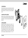
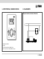
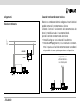
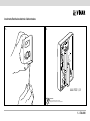
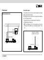
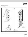
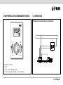
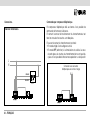
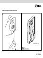
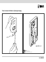
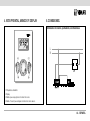
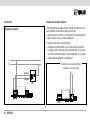
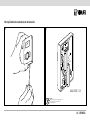
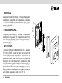
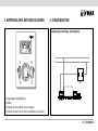
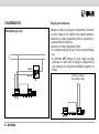
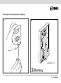
01915 - 01915.14 - 01915.20
Termostato elettronico da parete - Istruzioni
Surface - mounted electronic thermostat - Instruction handbook
Thermostat électronique en saillie - Notice technique
Elektronisches Thermostat zur Wandinstallation - Montageanweisungen
Termostato electrónico de superficie - Manual de Instrucciones
Θερμοστάτης ηλεκτρονικός επίτοιχος - Οδηγίες χρήσης
CLIMARADIO
01915 - 01915.14 - 01915.20
ITALIANO
Termostato elettronico da parete . . . . . . . . . . . . . . . . . . . . . . . . . . . . . . . . . . . . . . . . . . . . . . . . . . . . . . . . . . . . . . . 1
ENGLISH
Surface-mounted electronic thermostat . . . . . . . . . . . . . . . . . . . . . . . . . . . . . . . . . . . . . . . . . . . . . . . . . . . . . . . . . . 11
FRANÇAIS
Thermostat électronique en saillie . . . . . . . . . . . . . . . . . . . . . . . . . . . . . . . . . . . . . . . . . . . . . . . . . . . . . . . . . . . . . . 21
DEUTSCH
Elektronisches Thermostat zur Wandinstallation . . . . . . . . . . . . . . . . . . . . . . . . . . . . . . . . . . . . . . . . . . . . . . . . . . 31
ESPAÑOL
Termostato electrónico de superficie . . . . . . . . . . . . . . . . . . . . . . . . . . . . . . . . . . . . . . . . . . . . . . . . . . . . . . . . . . . . 41
ΕΛΛΗΝΙΚΑ
Ηλεκτρονικός θερμοστάτης επίτοιχος . . . . . . . . . . . . . . . . . . . . . . . . . . . . . . . . . . . . . . . . . . . . . . . . . . . . . . . . . . . 51
ATTENZIONE!
Se la visibilità del display diminuisce,
le batterie di alimentazione
si stanno esaurendo.
SOSTITUITELE QUANTO PRIMA!
INDICE.
1.Descrizione . . . . . . . . . . . . . . . . . . . . . . . . . . . . . . . . . . . . . . . . . . . . . . . . . . . . . . . . . . . . . . . . . . . . . . . . . . . . . . . . . . . . . . . . . . . 2
2. Campo di applicazione . . . . . . . . . . . . . . . . . . . . . . . . . . . . . . . . . . . . . . . . . . . . . . . . . . . . . . . . . . . . . . . . . . . . . . . . . . . . . . . . . . 2
3.Installazione . . . . . . . . . . . . . . . . . . . . . . . . . . . . . . . . . . . . . . . . . . . . . . . . . . . . . . . . . . . . . . . . . . . . . . . . . . . . . . . . . . . . . . . . . . 2
4. Vista frontale, comandi e display . . . . . . . . . . . . . . . . . . . . . . . . . . . . . . . . . . . . . . . . . . . . . . . . . . . . . . . . . . . . . . . . . . . . . . . . . . . 3
5.Collegamenti
Pompe di circolazione, bruciatori, elettrovalvole . . . . . . . . . . . . . . . . . . . . . . . . . . . . . . . . . . . . . . . . . . . . . . . . . . . . . . . . . . . . . . . 3
Valvole motorizzate . . . . . . . . . . . . . . . . . . . . . . . . . . . . . . . . . . . . . . . . . . . . . . . . . . . . . . . . . . . . . . . . . . . . . . . . . . . . . . . . . . . . . 4
Comando tramite combinatore telefonico . . . . . . . . . . . . . . . . . . . . . . . . . . . . . . . . . . . . . . . . . . . . . . . . . . . . . . . . . . . . . . . . . . . . 4
Inserimento/sostituzione batterie di alimentazione . . . . . . . . . . . . . . . . . . . . . . . . . . . . . . . . . . . . . . . . . . . . . . . . . . . . . . . . . . . . . . 5
6. Funzioni dei tasti . . . . . . . . . . . . . . . . . . . . . . . . . . . . . . . . . . . . . . . . . . . . . . . . . . . . . . . . . . . . . . . . . . . . . . . . . . . . . . . . . . . . . . . 6
7.Funzionamento . . . . . . . . . . . . . . . . . . . . . . . . . . . . . . . . . . . . . . . . . . . . . . . . . . . . . . . . . . . . . . . . . . . . . . . . . . . . . . . . . . . . . . . . 6
8. Principali caratteristiche . . . . . . . . . . . . . . . . . . . . . . . . . . . . . . . . . . . . . . . . . . . . . . . . . . . . . . . . . . . . . . . . . . . . . . . . . . . . . . . . . . 8
9. Regole di installazione . . . . . . . . . . . . . . . . . . . . . . . . . . . . . . . . . . . . . . . . . . . . . . . . . . . . . . . . . . . . . . . . . . . . . . . . . . . . . . . . . . . 9
10. Conformità normativa . . . . . . . . . . . . . . . . . . . . . . . . . . . . . . . . . . . . . . . . . . . . . . . . . . . . . . . . . . . . . . . . . . . . . . . . . . . . . . . . . . . 9
1 - ITALIANO
Termostato elettronico da parete per controllo temperatura ambiente
(riscaldamento e condizionamento), alimentazione mediante due batterie stilo AAA LR03 1,5 V (non fornite), uscita a relè in scambio 5(2)
A 250 V~
2. CAMPO DI APPLICAZIONE.
L’apparecchio è adatto a controllare la temperatura ambiente agendo
sul circuito di comando del bruciatore o della pompa di circolazione
(riscaldamento) o sul circuito di comando del condizionatore (condizionamento),
3. INSTALLAZIONE.
L’apparecchio deve essere installato a parete a un’altezza di 1,5 m
dal piano di calpestio, in una posizione idonea alla corretta rilevazione
della temperatura ambiente, evitando l’installazione in nicchie, dietro
porte e tende o zone influenzate da fonti di calore o fattori atmosferici.
La base dell’apparecchio è dotata di 2 asole per il fissaggio diretto
alla parete con viti e tasselli ø 6 mm (non forniti), Va utilizzato in luoghi
asciutti e non polverosi a temperatura compresa tra 0 °C e +40 °C.
2 - ITALIANO
60 mm
1. DESCRIZIONE.
4. VISTA FRONTALE, COMANDI E DISPLAY.
5. COLLEGAMENTI.
Pompe di circolazione, bruciatori, elettrovalvole.
1
2
3
L
N
3
4
U1
1. Temperatura ambiente.
2.Display.
3. Tasti per la programmazione delle funzioni.
4. Tasto “mouse” per il comando delle funzioni base.
3 - ITALIANO
Collegamenti.
Comando tramite combinatore telefonico.
Mediante un combinatore telefonico collegato ai morsetti dedicati è
possibile comandare il cronotermostato a distanza.
Chiudendo il contatto il funzionamento del cronotermostato viene
forzato in modalità manuale e i tasti vengono bloccati.
Aprendo il contatto il cronotermostato viene forzato:
•In modalità antigelo se sta funzionando il riscaldamento.
•In modalità OFF (spegnimento) se sta funzionando il condizionamento. In questa fase i tasti del cronotermostato non sono bloccati
ed è possibile effettuare qualsiasi operazione sul dispositivo.
Valvole motorizzate.
L
N
CHIUDE
APRE
U1
4 - ITALIANO
Collegamento con
attuatore telefonico
con contatto pulito
Inserimento/Sostituzione batterie di alimentazione.
1.
2.
:
IE S
ER V
TT
BA 1 , 5
3
2 x LR0
A
AA
AAA LR03 1,5 V
ATTENZIONE!
In caso di sostituzione, smaltire le batterie
negli appositi cassonetti per la raccolta differenziata.
5 - ITALIANO
6. FUNZIONI DEI TASTI.
Ogni tasto del termostato è multifunzione; per ognuno è indicata la
sequenza di selezione delle funzioni.
.
Tasto
1. Impostazione della temperatura di comfort.
2. Impostazione crescente o decrescente di valori numerici o selezione di altre funzioni.
.
Tasto
1.Selezione e impostazione temperatura ridotta; impostazione
.
mediante il tasto
2.Selezione e impostazione temperatura ridotta temporizzata;
.
impostazione mediante il tasto
.
Tasto
1. Selezione Off. 2. Selezione spento temporizzato; impostazione mediante il tasto
3. Selezione On.
4. Selezione e impostazione temperatura antigelo.
Tasto OK.
1. Memorizzazione e attivazione della selezione impostata.
6 - ITALIANO
.
Tasto
1. Selezione estate/inverno; impostazione mediante il tasto .
2. Selezione della temperatura differenziale; impostazione mediante
.
il tasto
3. Selezione dell’unità di misura della temperatura tra gradi Celsisus
e gradi Fahrenheit, scelta impostazione mediante il tasto .
7.FUNZIONAMENTO.
Effettuare i collegamenti elettrici, installare l’apparecchio, quindi
inserire le batterie. Selezionare la funzione richiesta premendo il
relativo tasto. La visualizzazione di un dato lampeggiante indica la
. Il tasto OK
possibilità della sua modifica attraverso il tasto
permette di confermare la scelta; un tasto diverso cancella la selezione.
•LIVELLI DI TEMPERATURA.
E’ possibile scegliere fra diversi livelli di temperatura: Comfort,
), Antigelo (simbolo
).
Ridotto (simbolo
Se il relè è attivato, viene visualizzato il simbolo
simbolo
in estate.
in inverno o il
Il simbolo
indica la presenza del modulo TX radio o la mancanza del modulo relè. Attendere 2 minuti max per il riconoscimento
automatico oppure eseguire l’operazione di reset.
).
•FUNZIONAMENTO TEMPORIZZATO (simbolo
Alla fine del tempo in ore prestabilito, il termostato ritorna al funzionamento con il livello di temperatura Comfort.
•SPENTO.
E’ possibile scegliere tra Spento (simbolo OFF) e Spento temporizzato, in quest’ultimo caso viene visualizzato anche il tempo
rimanente in ore prima della riaccensione, tempo che può essere
e confermato con il tasto OK.
modificato con il tasto
•DIFFERENZIALE TERMICO.
Consente di impostare il valore del differenziale termico.
Per differenziale termico si intende la differenza tra il valore di
temperatura impostato e l’effettiva temperatura di accensione o di
spegnimento dell’impianto. Adeguando il differenziale termico al tipo
di impianto se ne evitano continue accensioni e spegnimenti; impianti
ad alta inerzia (ad esempio impianti con radiatori in ghisa) necessitano
di un valore basso di differenziale termico, mentre impianti a bassa
inerzia (ad esempio ventil-convettori) necessitano di un valore alto.
Esempio.
Impostando la temperatura ambiente a 20 °C e il differenziale
termico a 0,3 °C, l’impianto si accenderà quando la temperatura
ambiente scenderà a 19,7 °C e si spegnerà quando raggiungerà i
20,3 °C.
• SCALA DI TEMPERATURA.
Consente di impostare l’unità di misura della temperatura, scegliendo tra gradi Celsius e gradi Fahrenheit.
•RESET.
e OK il termosta Premendo contemporaneamente i tasti ,
to si resetta e ritorna ai seguenti valori di default:
- temperatura Comfort: 20 °C
- temperatura ridotta: 15 °C
- temporizzazione di Off: 12h
- temporizzazione temperatura ridotta: 12h
- antigelo: 5 °C.
- differenziale termico: 0,2 °C.
- visualizzazione gradi e inverno.
7 - ITALIANO
8. PRINCIPALI CARATTERISTICHE
•Alimentazione: 3 V d.c. mediante 2 batterie stilo AAA LR03 1,5 V
(non fornite)
•Durata della batteria: superiore ad un anno
•Uscita: a relè con contatto pulito in scambio 5(2) A 250 V~
•Tipo di regolazione: ON/OFF
•Possibilità di collegamento in radiofrequenza ad attuatori 01923
e 01924 previa sostituzione del modulo relè con il modulo trasmettitore 01921.1 (per ulteriori informazioni si veda il catalogo
generale)
•Aggiornamento della temperatura visualizzata: ogni 20 s
•Visualizzazione temperatura ambiente: 0 °C +40 °C
•Risoluzione della lettura: 0,1 °C
•Risoluzione delle impostazioni: 0,1 °C
•Precisione della lettura:
- ≤ ±0,5 °C tra +15 °C e +30 °C
- ≤ ±0,8 °C agli estremi
•Campo di regolazione:
- +4 °C - +15 °C in antigelo
- +5 °C - +35 °C in riscaldamento o condizionamento
•Differenziale termico: regolabile da 0,1 °C a 1 °C
8 - ITALIANO
•Funzioni principali:
- selezione tra 3 livelli di temperatura: comfort, ridotta, antigelo
- possibilità di selezione della temperatura ridotta temporizzata
- impostazione tra riscaldamento e condizionamento
- possibilità di spegnimento o spegnimento temporizzato
- possibilità di attivazione e disattivazione tramite attuatore telefonico
- possibilità di visualizzazione in gradi Celsius o Fahrenheit
- memorizzazione di tutte le impostazioni
•Grado di protezione: IP30
•Apparecchio di classe II:
•Numero di cicli manuali: 3.000
•Numero di cicli automatici: 100.000
•Tipo di apertura dei contatti: microinterruzione
•Tipo di azione: 1B
•Indice di tracking: PTI175
•Situazione di polluzione: 2 (normale)
•Tensione impulsiva nominale: 4000 V
•Temperatura ambiente durante il trasporto: -25 °C +60 °C
•Temperatura di funzionamento: T40 (0 °C +40 °C)
•Classe del software: A
9. REGOLE DI INSTALLAZIONE.
L’installazione deve essere effettuata con l’osservanza delle disposizioni regolanti l’installazione del materiale elettrico in vigore nel paese
dove i prodotti sono installati.
10. CONFORMITÀ NORMATIVA.
Direttiva BT
Direttiva EMC
Norme EN 60730-1, EN 60730-2-9.
9 - ITALIANO
CAUTION!
If the display visibility decreases, the
power batteries are running low.
REPLACE THEM
AS SOON AS POSSIBLE!
CONTENTS.
1.Description . . . . . . . . . . . . . . . . . . . . . . . . . . . . . . . . . . . . . . . . . . . . . . . . . . . . . . . . . . . . . . . . . . . . . . . . . . . . . . . . . . . . . . . . . . . 12
2.Scope . . . . . . . . . . . . . . . . . . . . . . . . . . . . . . . . . . . . . . . . . . . . . . . . . . . . . . . . . . . . . . . . . . . . . . . . . . . . . . . . . . . . . . . . . . . . . . . 12
3.Installation . . . . . . . . . . . . . . . . . . . . . . . . . . . . . . . . . . . . . . . . . . . . . . . . . . . . . . . . . . . . . . . . . . . . . . . . . . . . . . . . . . . . . . . . . . . . 12
4. Front view and view of controls . . . . . . . . . . . . . . . . . . . . . . . . . . . . . . . . . . . . . . . . . . . . . . . . . . . . . . . . . . . . . . . . . . . . . . . . . . . . 13
5.Connections
Circulation pumps, burners, solenoid valves . . . . . . . . . . . . . . . . . . . . . . . . . . . . . . . . . . . . . . . . . . . . . . . . . . . . . . . . . . . . . . . . .
Motor-operated valves . . . . . . . . . . . . . . . . . . . . . . . . . . . . . . . . . . . . . . . . . . . . . . . . . . . . . . . . . . . . . . . . . . . . . . . . . . . . . . . . .
Phone dialler control . . . . . . . . . . . . . . . . . . . . . . . . . . . . . . . . . . . . . . . . . . . . . . . . . . . . . . . . . . . . . . . . . . . . . . . . . . . . . . . . . . . .
Fitting/Replacing power batteries . . . . . . . . . . . . . . . . . . . . . . . . . . . . . . . . . . . . . . . . . . . . . . . . . . . . . . . . . . . . . . . . . . . . . . . . .
13
14
1 4
15
6. Functions of the buttons . . . . . . . . . . . . . . . . . . . . . . . . . . . . . . . . . . . . . . . . . . . . . . . . . . . . . . . . . . . . . . . . . . . . . . . . . . . . . . . . . 16
7.Operation . . . . . . . . . . . . . . . . . . . . . . . . . . . . . . . . . . . . . . . . . . . . . . . . . . . . . . . . . . . . . . . . . . . . . . . . . . . . . . . . . . . . . . . . . . . . 16
8.Characteristics . . . . . . . . . . . . . . . . . . . . . . . . . . . . . . . . . . . . . . . . . . . . . . . . . . . . . . . . . . . . . . . . . . . . . . . . . . . . . . . . . . . . . . . . 18
9. Installation rules . . . . . . . . . . . . . . . . . . . . . . . . . . . . . . . . . . . . . . . . . . . . . . . . . . . . . . . . . . . . . . . . . . . . . . . . . . . . . . . . . . . . . . . 19
10. Conformity to standards . . . . . . . . . . . . . . . . . . . . . . . . . . . . . . . . . . . . . . . . . . . . . . . . . . . . . . . . . . . . . . . . . . . . . . . . . . . . . . . . . 19
11 - ENGLISH
1. DESCRIPTION.
2. SCOPE.
The thermostat is suitable for ambient temperature control by regulating the supply circuit of the burner or heat pump (heating), or the
supply circuit of the air conditioner (air conditioning).
3. INSTALLATION.
The thermostat must be mounted on surface at a height of 1,5
m above floor level, in an appropriate position for measuring the
ambient temperature; do not position the instrument inside niches,
behind doors and curtains, close to heat sources or in areas influenced by outside weather conditions.
The base of the device has 2 slots placed 60 mm apart for fastening
directly to the wall with ø 6 mm screws and studs.
Use in dry, non-dusty environments at a temperature between 0
°C and +40 °C.
12 - ENGLISH
60 mm
Surface-mounted electronic thermostat to control ambient temperature (heating and air-conditioning), exchange relay output 5(2) A
250 V~, powered by two AAA batteries LR03 1.5 V (not included).
4. FRONT VIEW AND VIEW OF CONTROLS.
5. CONNECTIONS.
Circulation pumps, burners, solenoid valves.
1
2
3
L
N
3
4
U1
1. Ambient temperature.
2.Display.
3. Function setting buttons.
4. “Mouse” button to control the basic functions.
13 - ENGLISH
Connections.
Phone dialler control.
It is possible to control the timer-thermostat remotely with a phone
dialler connected to the terminals.
By closing the contact, the thermostat is forced onto manual operation and the keys are locked.
Motor-operated valves.
On opening the contact the timer-thermostat is forced onto:
• Antifreeze mode if heating is on.
• OFF if air-conditioning is on. In this phase the keys of the timerthermostat are not locked and it is possible to operate the device.
L
N
CLOSE
OPEN
U1
14 - ENGLISH
Connection to a telephone
actuator with clean contact
Fitting/Replacing power batteries.
1.
2.
:
IE S
ER V
TT
BA 1 , 5
3
2 x LR0
A
AA
AAA LR03 1,5 V
ATTENTION!
After replacing the battery, dispose of the old battery
in the appropriate sorted refuse bins.
15 - ENGLISH
6. FUNCTIONS OF THE BUTTONS.
Every button on the thermostat has multiple functions; the function
selection sequence is indicated for each.
.
Button
1. Set the comfort temperature.
2. Increase or decrease numerical values or select other functions.
.
Button
1. Select and set the reduced temperature; set by means of the
button.
2. Select and set the timed reduced temperature; set by means of
button.
the
.
Button
1. Select Off. 2. Select timed off; set by means of the
3. Select On.
4. Select and set antifreeze temperature.
button.
Button OK.
1. Save and activate the set selection.
.
Button
1. Select summer/winter; set by means of the
16 - ENGLISH
2. Select the differential temperature; set by means of the button.
3. Select the unit of measure for temperature, between degrees Celsius and degrees Fahrenheit; choose setting by means of the
button.
7.OPERATION.
Complete the electrical connections, install the device, then insert
the batteries. Select the required function by pressing the corresponding button. A flashing figure on the display indicates that it may
button. The OK button confirms
be changed by means of the
the choice; any other button cancels the selection.
• TEMPERATURE LEVELS.
It is possible to choose between different temperature levels:
symbol), Antifreeze (
symbol).
Comfort, Reduced (
If the relay is activated, the symbol
in summer.
symbol
button.
The symbol
the
is displayed in winter or the
indicates that the TX radio module is present or
relay module is missing. Wait no more than 2 minutes for automatic
recognition, or reset the device.
• TIMED OPERATION (
symbol).
At the end of the set time in hours, the thermostat returns to operating at the Comfort temperature level.
•OFF.
You may choose between Off (OFF symbol) and Timed off. In the
latter instance, the remaining time in hours until restarting is disbutton and conplayed; this time may be changed using the
firmed with OK button.
•HYSTERESIS.
Adjusts the value of the temperature hysteresis parameter.
Hysteresis is the amount by which the ambient temperature can
deviate from the set-point before the system is switched on and
off. By adapting the hysteresis parameter to the type of system, it
is possible to prevent repeated switch-on and switch-off around
the set-point value; systems with high inertia (for example with cast
iron radiators) require a low hysteresis value, whereas systems with
low inertia (for example fan-convectors) require a higher value.
Example.
With a temperature set-point of 20 °C and a hysteresis of 0.3 °C,
the system will switch on when the ambient temperature drops
below 19.7 °C, and will switch off when the ambient temperature
reaches 20.3 °C.
• TEMPERATURE SCALE.
Used for setting the units of measurement for temperature, choosing between degrees Celsius and degrees Fahrenheit.
•RESET.
and OK buttons, the ther Simultaneously pressing the ,
mostat resets and returns to the following default values:
- Comfort temperature: 20 °C
- reduced temperature: 15 °C
- Off timer: 12h
- reduced temperature timer: 12 h
- antifreeze: 5 °C.
- thermal differential: 0,2 °C.
- degrees and winter display.
17 - ENGLISH
8. CHARACTERISTICS
•Supply voltage: 3 V d.c. with 2 AAA LR6 1,5 V batteries (not included)
• Batteries life: up to 1 year
•Output: 5(2) A 250 V~ change-over relay output
• Type of regulation: ON/OFF
•It is possible to create a radio link with actuators 01923 and 01924
by replacing the relay module with the transmitter module 01921.1
(more information in the general catalogue)
• Updating of display temperature: every 20 s
• Ambient temperature display range: 0 °C +40 °C
• Resolution of the reading: 0,1 °C
• Resolution of the settings: 0,1 °C
• Precision of the reading:
- ≤ ±0,5 °C between +15 °C and +30 °C
- ≤ ±0,8 °C at the temperature extremes
• Hysteresis: adjustable between 0,1 °C and 1 °C
• Thermostat operating range:
- +4 °C - +15 °C in antifreeze mode
- +5 °C - +35 °C in heating or cooling mode
• Principal functions:
18 - ENGLISH
• Main functions:
- select among 3 temperature levels: comfort, reduced, antifreeze
- possibility of selecting timed reduced temperature
- possibility of regular or timed shutdown
- setting between heating and air-conditioning
- possibility of activation through a telephone actuator
- select between display in degrees Celsius and Fahrenheit
- save all settings
• Protection degree: IP30
• Class II equipment:
• Number of manual cycles: 3.000
• Number of automatic cycles: 100.000
• Type of contact opening: micro-breakdown
• Type of action: 1CU
• Tracking index: PTI175
• Pollution status: 2 (normal)
• Impulsive rated voltage: 4000 V
• Ambient temperature range during transport: -25 °C +60 °C
• Operating temperature: T40 (0 °C +40 °C)
•Software class: A
9. INSTALLATION RULES.
The installation must be done according to rules for electrical installations of buildings in force in the country where the products are
installed.
10. CONFORMITY TO STANDARDS.
LV Directive
EMC Directive
Standards EN 60730-1, EN 60730-2-9
19 - ENGLISH
ATTENTION !
Lorsque la visibilité du frontal décroît,
les batteries d’alimentation sont
proches de l’usure.
REMPLACER LES BATTERIES DES
QUE POSSIBLE !
TABLES DES MATIERES.
1.Description. . . . . . . . . . . . . . . . . . . . . . . . . . . . . . . . . . . . . . . . . . . . . . . . . . . . . . . . . . . . . . . . . . . . . . . . . . . . . . . . . . . . . . . . . . . . 22
2. Domaine d’application. . . . . . . . . . . . . . . . . . . . . . . . . . . . . . . . . . . . . . . . . . . . . . . . . . . . . . . . . . . . . . . . . . . . . . . . . . . . . . . . . . . 22
3.Installation. . . . . . . . . . . . . . . . . . . . . . . . . . . . . . . . . . . . . . . . . . . . . . . . . . . . . . . . . . . . . . . . . . . . . . . . . . . . . . . . . . . . . . . . . . . . . 22
4. Vue frontale, vue commandes et display. . . . . . . . . . . . . . . . . . . . . . . . . . . . . . . . . . . . . . . . . . . . . . . . . . . . . . . . . . . . . . . . . . . . . . 23
5.Connexions
Pompes de circulation, brûleurs, électrovannes . . . . . . . . . . . . . . . . . . . . . . . . . . . . . . . . . . . . . . . . . . . . . . . . . . . . . . . . . . . . . . . .
Vannes motorisées. . . . . . . . . . . . . . . . . . . . . . . . . . . . . . . . . . . . . . . . . . . . . . . . . . . . . . . . . . . . . . . . . . . . . . . . . . . . . . . . . . . . . .
Commande par actuateur téléphonique. . . . . . . . . . . . . . . . . . . . . . . . . . . . . . . . . . . . . . . . . . . . . . . . . . . . . . . . . . . . . . . . . . . . . .
Introduction/Remplacement batteries alimentation. . . . . . . . . . . . . . . . . . . . . . . . . . . . . . . . . . . . . . . . . . . . . . . . . . . . . . . . . . . . . .
23
24
24
25
6. Fonctions des touches. . . . . . . . . . . . . . . . . . . . . . . . . . . . . . . . . . . . . . . . . . . . . . . . . . . . . . . . . . . . . . . . . . . . . . . . . . . . . . . . . . . 26
7.Fonctionnement . . . . . . . . . . . . . . . . . . . . . . . . . . . . . . . . . . . . . . . . . . . . . . . . . . . . . . . . . . . . . . . . . . . . . . . . . . . . . . . . . . . . . . . . 26
8. Caractéristiques techniques . . . . . . . . . . . . . . . . . . . . . . . . . . . . . . . . . . . . . . . . . . . . . . . . . . . . . . . . . . . . . . . . . . . . . . . . . . . . . . . 28
9. Règles d’installation . . . . . . . . . . . . . . . . . . . . . . . . . . . . . . . . . . . . . . . . . . . . . . . . . . . . . . . . . . . . . . . . . . . . . . . . . . . . . . . . . . . . . 29
10. Conformité aux Normes . . . . . . . . . . . . . . . . . . . . . . . . . . . . . . . . . . . . . . . . . . . . . . . . . . . . . . . . . . . . . . . . . . . . . . . . . . . . . . . . . . 29
21 - FRANÇAIS
1. DESCRIPTION.
2. DOMAINE D’APPLICATION.
Cet appareil est en mesure de contrôler la température ambiante en
agissant sur le circuit d'alimentation du brûleur ou du circulateur (chauffage), ou sur le circuit d'alimentation du climatiseur (climatisation).
3. INSTALLATION.
L’appareil doit être installé en saillie à une hauteur de 1,5 m au-dessus du sol, dans une position appropriée au relevé de la température
ambiante ; en évitant par conséquent l’installation dans des niches,
derrière des portes et des rideaux ou des zones à proximité de sources de chaleur ou subissant l’influence de phénomènes et facteurs
atmosphériques. La base de l’appareil est dotée de 2 oeillets, avec
interaxe 60 mm pour la fixation murale à vis et cheville ø 6 mm. Cet
appareil doit être utilisé en lieu sec et exempt de poussière, à une
température comprise entre 0 °C e +40 °C.
22 - FRANÇAIS
60 mm
Thermostat électronique en saillie de contrôle de la température
ambiante (chauffage et climatisation), sortie par relais inverseur 5(2)
A 250 V~, alimentation par mini piles alcalines 2x1,5 V AAA LR03
(non fournies).
4. VUE FRONTALE, VUE COMMANDES ET DISPLAY.
5. CONNEXIONS.
Pompes de circulation, brûleurs, électrovannes.
1
2
3
L
N
3
4
U1
1. Température ambiante.
2.Display.
3. Touches pour le réglage de la fonction.
4. Touche “mouse” pour commander les fonctions de base.
23 - FRANÇAIS
Connexions.
Commande par composeur téléphonique.
Par composeur téléphonique relié aux bornes il est possible de
commander le thermostat à distance.
En fermant le contact le fonctionnement du chronothermostat est
forcé en manuel et les touches sont bloquées.
Vannes motorisées.
En ouvrant le contact le chonothermostat est forcé:
• En mode antigel si le chauffage est activé.
• En mode OFF (extinction) si la climatisation est activée. Au cours
de cette phase, les touches du chronothermostat ne sont pas bloquées et il est possible d’effectuer toute opération sur le dispositif.
L
N
Connexion avec actuateur
téléphonique avec contact vierge
FERME
OUVERT
U1
24 - FRANÇAIS
Introduction/Remplacement batteries alimentation.
1.
2.
:
IE S
ER V
TT
BA 1 , 5
3
2 x LR0
A
AA
AAA LR03 1,5 V
ATTENTION !
En cas de remplacement, les batteries usées
devront être jetées dans des poubelles ou
des conteneurs spéciaux de collecte sélective.
25 - FRANÇAIS
6. FONCTIONS DES TOUCHES.
Chaque thermostat est multifonction ; dans chaque cas la séquence
de sélection des fonctions est précisée.
.
Touche
1. Réglage de la température de confort.
2. Réglage croissant et décroissant de valeurs numériques ou sélection d’autres fonctions.
.
Touche
1. Sélection et réglage faible température; réglage avec la touche
.
2. Sélection et réglage faible température temporisée; réglage avec
.
la touche
.
Touche
1. Sélection Off. 2. Sélection éteint temporisé ; réglage avec la touche
3. Sélection On. 4. Sélection et réglage température hors gel.
Touche OK.
1. Mémorisation et activation de la sélection réglée.
26 - FRANÇAIS
.
.
Touche
.
1. Sélection été/hiver ; réglage avec la touche
2. Sélection de la température différentielle; réglage avec la touche
.
3. Sélection de l’unité de mesure de la température, en degrés Celsius et degrés Fahrenheit, sélection du réglage avec la touche
.
7.FONCTIONNEMENT.
Effectuer les connexions électriques, installer l’appareil, puis introduire les batteries. Sélectionner la fonction demandée en pressant la
touche correspondante. La visualisation clignotante d’une donnée
indique la possibilité de modifier cette donnée en agissant sur la
. La touche OK permet de confirmer le choix effectué ;
touche
une autre touche annule la sélection.
• NIVEAU DE TEMPERATURE.
Il est possible d’effectuer un choix entre plusieurs niveaux de tem), Hors gel (symbole
).
pérature : Confort, Faible (symbole
Si le relais est actif, le symbole
en été.
bole
est visualisé en hiver, le sym-
Le symbole
indique la présence du module TX radio ou l’absence du
module de relais. Patienter 2 minutes au maximum
pour permettre l’identification automatique ou bien effectuer l’opération de reset.
).
• FONCTIONNEMENT TEMPORISE (symbole
A l’expiration du temps prédéfini en heures, le
thermostat retourne au fonctionnement avec le niveau de température
Confort.
•ETEINT.
Il est possible de choisir entre Eteint (symbole OFF) et Eteint temporisé, dans ce dernier cas le temps restant en heures est visualisé avant le rallumage. Ce temps peut être modifié en agissant sur
puis en confirmant avec la touche OK.
la touche
•HYSTERESIS.
Permet de régler la valeur de l’hystérésis.
L’hystérésis est la différence entre la valeur de température réglée
et la température réelle d’allumage et extinction de l’installation. En
adaptant l’hystérésis au type d’installation on en évite les allumages et les extinctions permanentes et répétées ; les installations
caractérisées par une forte inertie (par exemple les installations
avec des radiateurs en fonte) ont besoin d’une faible valeur d’hys-
térésis tandis que pour les installations avec une faible inertie (par
exemple les ventil-convecteurs une valeur haute est nécessaire.
Exemple.
En réglant la température ambiante sur 20 °C et l’hystérésis sur
0,3 °C, l’installation s’allumera quand la température ambiante arrivera à 19,7 °C et s’éteindra quand elle parviendra à 20,3 °C.
• PLAGE DE TEMPERATURE.
Permet de régler l’unité de mesure de la température, en choisissant entre degrés Celsius et degrés Fahrenheit.
•RESET.
En pressant en même temps les touches
mostat se réinitialise et retourne aux valeurs
dessous :
- température Confort : 20 °C
- faible température : 15 °C
- temporisation de Off : 12h
- temporisation faible température : 12h
- hors gel : 5 °C.
- hystérèse : 0,2 °C.
- visualisation degrés et hiver.
,
et OK le therde défaut ci-
27 - FRANÇAIS
8. CARACTERISTIQUES TECHNIQUES
•Alimentation : 3 V c.c. avec 2 piles alcalines AAA LR6 1,5 V (non
fournies)
• Autonimie des batteries : au-dessus d’un an
• Sortie : relais inverseur 5(2) A 250 V~
• Type de réglage : ON/OFF
• Possibilité de connexion en radiofréquence avec actuateurs 01923
et 01924 après remplacement du module à relais par le module
émetteur 01921.1 (pour plus d’informations veuillez consulter le
catalogue général)
• Mise à jour température affichée : chaque 20 s
• Affichage température ambiante : de 0 °C à +40 °C
• Résolution de la lecture : 0,1 °C
• Résolution des programmations : 0,1 °C
• Précision de la lecture :
- ≤ ±0,5 °C entre +15 °C et +30 °C
- ≤ ±0,8 °C aux extrêmes
• Hystérésis : réglable de 0,1 °C à 1 °C
• Plage de réglage :
- +4 °C - +15 °C en horsgel
- +5 °C - +35 °C en chauffage ou climatisation
28 - FRANÇAIS
• Fonctions principales :
- sélection entre 3 niveaux de température : confort, faible, hors gel
- possibilité de sélection de la faible température temporisée
- possibilité d’extinction ou d’extinction temporisée
- réglage entre chauffage et climatisation
- possibilité d’activation par actuateur téléphonique
- sélection entre visualisation en degrés Celsius et Fahrenheit
- mémorisation de tous les réglages
• Degré de protection : IP30
• Appareil de classe II :
• Nombre de cycles manuels : 3.000
• Nombre de cycles automatiques : 100.000
• Type d’ouverture des contacts : microinterruption
• Type d’action : 1CU
• Indice de tracking : PTI175
• Effets en matière de pollution : 2 (normal)
• Tension nominal impulsive : 4000 V
• Température ambiante pendant le transport : -25 °C +60 °C
• Température de fonctionnement : T40 (0 °C +40 °C)
•Classe du logiciel: A
9. REGLES D’INSTALLATION.
L’installation doit être effectuée selon les normes pour les installations électriques des bâtiments en viguer dans le Pays oú les
produits sont installés.
10. CONFORMITE AUX NORMES.
Directive BT
Directive EMC
Normes EN 60730-1, EN 60730-2-7, EN 60730-2-9
29 - FRANÇAIS
ACHTUNG!
Wenn die Helligkeit des Displays
nachläßt, weist dies darauf hin, daß die
Ladung der Batterien zuende geht.
IN DIESEM FALL SO BALD WIE MÖGLICH NEUE BATTERIEN EINSETZEN!
INHALT.
1.Beschreibung. . . . . . . . . . . . . . . . . . . . . . . . . . . . . . . . . . . . . . . . . . . . . . . . . . . . . . . . . . . . . . . . . . . . . . . . . . . . . . . . . . . . . . . . . . 32
2.Anwendungsbereich. . . . . . . . . . . . . . . . . . . . . . . . . . . . . . . . . . . . . . . . . . . . . . . . . . . . . . . . . . . . . . . . . . . . . . . . . . . . . . . . . . . . . 32
3.Installation. . . . . . . . . . . . . . . . . . . . . . . . . . . . . . . . . . . . . . . . . . . . . . . . . . . . . . . . . . . . . . . . . . . . . . . . . . . . . . . . . . . . . . . . . . . . . 32
4. Vorderansicht, Tasten und Display. . . . . . . . . . . . . . . . . . . . . . . . . . . . . . . . . . . . . . . . . . . . . . . . . . . . . . . . . . . . . . . . . . . . . . . . . . . 33
5.Anschlüsse
Umlaufpumpen, Brenner, Magnetventile . . . . . . . . . . . . . . . . . . . . . . . . . . . . . . . . . . . . . . . . . . . . . . . . . . . . . . . . . . . . . . . . . . . . . .
Gesteuerte Ventile. . . . . . . . . . . . . . . . . . . . . . . . . . . . . . . . . . . . . . . . . . . . . . . . . . . . . . . . . . . . . . . . . . . . . . . . . . . . . . . . . . . . . . .
Steuerung durch Telefontrieb . . . . . . . . . . . . . . . . . . . . . . . . . . . . . . . . . . . . . . . . . . . . . . . . . . . . . . . . . . . . . . . . . . . . . . . . . . . . . .
Einsatz / Austausch der Batterien zur Spannungsversorgung . . . . . . . . . . . . . . . . . . . . . . . . . . . . . . . . . . . . . . . . . . . . . . . . . . . . . .
33
34
34
35
6. Funktionsbelegung der Tasten. . . . . . . . . . . . . . . . . . . . . . . . . . . . . . . . . . . . . . . . . . . . . . . . . . . . . . . . . . . . . . . . . . . . . . . . . . . . . . 36
7.Funktionsweise . . . . . . . . . . . . . . . . . . . . . . . . . . . . . . . . . . . . . . . . . . . . . . . . . . . . . . . . . . . . . . . . . . . . . . . . . . . . . . . . . . . . . . . . 36
8. Wesentliche Daten . . . . . . . . . . . . . . . . . . . . . . . . . . . . . . . . . . . . . . . . . . . . . . . . . . . . . . . . . . . . . . . . . . . . . . . . . . . . . . . . . . . . . . 38
9. Anweisungen für die Installation . . . . . . . . . . . . . . . . . . . . . . . . . . . . . . . . . . . . . . . . . . . . . . . . . . . . . . . . . . . . . . . . . . . . . . . . . . . . 39
10. Entsprechung zu den Normen. . . . . . . . . . . . . . . . . . . . . . . . . . . . . . . . . . . . . . . . . . . . . . . . . . . . . . . . . . . . . . . . . . . . . . . . . . . . . . 39
31 - DEUTSCH
1. BESCHREIBUNG.
2. ANWENDUNGSBEREICH.
Das Gerät kontrolliert die Raumtemperatur durch Einwirkung auf
den Versorgungskreis des Brenners oder der Umlaufpumpe (Heizung) oder auf den Versorgungskreis der Klimaanlage, wodurch es
täglich, die ganze Woche hindurch, die Idealtemperatur sichert.
3. INSTALLATION.
Das Gerät muss in Aufputz installieren, auf einer Höhe von 1,5 m
vom Boden an einer Stelle installiert sein, die die richtige Erfassung
der Raumtemperatur gestattet; zu vermeiden ist die Installation in
Nischen, hinter Türen und Vorhängen oder in Bereichen, die durch
Wärmequellen oder Wetterfaktoren beeinflusst werden. Das Unterteil des Geräts ist mit 2 Bohrungen im Abstand 60 mm zur Wandbefestigung mittels Schrauben und Dübeln ø 6 mm ausgestattet. Das
Gerät muß in trockenen, nicht staubigen Räumen mit einer Raumtemperatur zwischen 0 °C und +40 °C installiert werden.
32 - DEUTSCH
60 mm
Elektronisches Wandthermostat zur Steuerung der Raumtemperatur
(Heizung und Klimaanlage), Wechselrelaisausgang 5(2) A 250 V~,
Spannungsversorgung über Ministyle-Batterien 2 x 1,5 V AAA LR03
(nicht mitgeliefert).
4. VORDERANSICHT, TASTEN UND DISPLAY.
5. ANSCHLÜSSE.
Umlaufpumpen, Brenner, Magnetventile.
1
2
3
L
N
3
4
U1
1.Raumtemperatur.
2.Display.
3. Tasten zur Funktionsregelung.
4. "Maus"-Taste zur Steuerung der Grundfunktionen.
33 - DEUTSCH
Anschlüsse.
Steuerung über Telefonschaltung.
Der Uhrenthermostat kann über eine an die Klemmen angeschlossene Telefonschaltung fernbedient werden.
Durch Schließen des Kontakts wird der Uhrenthermostat auf Manuell geschaltet, die Tasten werden deaktiviert.
Gesteuerte Ventile.
Durch Öffnen des Kontakts wird der Uhrenthermostat umgeschaltet
auf:
• Frostschutz, wenn die Heizfunktion aktiviert ist.
• OFF (aus), wenn die Klimaanlagenfunktion aktiviert ist. In dieser
Phase sind die Tasten des Uhrenthermostats nicht deaktiviert, alle
Bedienelemente sind freigegeben.
L
N
Verbindung durch Telefontrieb
mit sauberem Kontakt
SCHLIESSEN
ÖFFNEN
34 - DEUTSCH
U1
Einsatz / Austausch der Batterien zur Spannungsversorgung.
1.
2.
:
IE S
ER V
TT
BA 1 , 5
3
2 x LR0
A
A
A
AAA LR03 1,5 V
ACHTUNG!
Bei Austausch der Batterien diese
in den entsprechenden Trennmüll-Tonnen entsorgen.
35 - DEUTSCH
6. FUNKTIONSBELEGUNG DER TASTEN.
Die Taste des Thermostats sind als sog. Multifunktionstasten ausgelegt;
für jede Taste wird die entsprechende Funktionssequenz angezeigt.
.
Taste
1. Einstellung der "Komfort"-Temperatur.
2. Steigerung oder Reduzierung der numerischen Werte oder Selektion weiterer Funktionen.
.
Taste
1.Selektion und Einstellung "reduzierte Temperatur"; Einstellung
.
über Taste
2.Selektion und Einstellung "reduzierte Temperatur" über Timer;
.
Einstellung über Taste
.
Taste
1. Selektion Off. 2. Selektion Ausschaltung über Timer; Einstellung über Taste
3. Selektion On. 4. Selektion und Einstellung der Temperatur "Frostschutz".
Taste OK.
1. Speicherung und Aktivierung der Selektionseinstellung.
36 - DEUTSCH
.
.
Taste
.
1. Selektion Sommer / Winter; Einstellung über Taste
.
2. Selektion Temperaturdifferenz; Einstellung über Taste
3. Selektion der Einheit zur Temperaturanzeige (°Celsius oder ° Fahren.
heit), Wahl über Taste
7.FUNKTIONSWEISE.
Führen Sie die elektrischen Anschlüsse aus, installieren Sie das Gerät an
der Wand, und setzten Sie die Batterien ein. Selektionieren Sie die gewünschte Funktion, indem Sie die entsprechende Taste drücken. Wenn
modifiziert
ein Wert blinkend angezeigt wird, kann er über die Taste
werden. Mit der Taste OK können Sie die Selektion bestätigen; bei Betätigung einer anderen Taste wird die Selektion annulliert.
•TEMPERATURSTUFEN.
Sie können zwischen den Temperaturstufen Komfort, reduzierte
) und Frostschutz (Symbol
) wählen.
Temperatur (Symbol
Wenn das entsprechende Relais aktiviert wird, erscheint im Winter
bzw. im Sommer das Symbol
.
das Symbol
Das Symbol
zeigt die Präsenz des Funkübertragungsmoduls
oder die Nichtpräsenz des Relaismoduls an. Warten Sie zur automatischen Erkennung max. 2 Minuten ab oder führen Sie den Vorgang zur Rücksetzung des Thermostats aus.
• BETRIEB ÜBER TIMER (Symbol
).
Nach Ablauf der eingestellten Uhrzeit kehrt das Gerät automatisch
in die Betriebsart Temperaturstufe Komfort zurück.
•AUS.
Sie können zwischen dem Status Aus (Symbol OFF) und Ausschaltung über timer wählen. Im letzteren Fall wird die vor der
erneuten Einschaltung verbleibende Zeit angezeigt; diese Zeit
kann über die Taste
modifiziert werden; anschließend müssen
Sie zur Bestätigung die Taste OK drücken.
•HYSTERESE.
Um den Wert des Wärmedifferentials einzustellen.
Unter hysterese ist die Differenz zwischen dem eingestellten Temperaturwert und der tatsächlichen Temperatur bei Ein- oder Ausschaltung
der Anlage zu verstehen. Bei Angleichung des Wärmedifferentials an
die Art der Anlage wird ständiges Ein- und Ausschalten vermieden;
Anlagen mit geringer Ansprechempfindlichkeit (z.B. Anlagen mit Radiatoren aus Gusseisen) benötigen einen niederen Differentialwert,
während Anlagen mit hoher Ansprechempfindlichkeit (z.B. Ventil-Konvektoren) einen hohen Wert benötigen.
Ein Beispiel.
Bei Einstellung der Raumtemperatur auf 20 °C und des Wärmedifferentials auf 0,3 °C schaltet sich die Anlage ein, wenn die Raumtemperatur auf 19,7 °C sinkt, während sie sich bei Erreichen von
20,3 °C ausschaltet.
•TEMPERATURSKALA.
Um die Maßeinheit der Temperatur einzustellen: Celsius- oder Fahrenheitgrade.
• RESET (RÜCKSETZUNG).
Wenn Sie gleichzeitig die Taste
, die Taste
die Taste OK
drücken, wird das Gerät auf folgende Standardwerte zurückgesetzt:
- Temperatur Komfort: 20 °C
- reduzierte Temperatur: 15 °C
- Zeitschaltung AUS: 12 h
- reduzierte Temperatur über Timer: 12 h
- Frostschutz: 5 °C.
- Temperaturdifferenz: 0,2 °C.
- Abbildung Grade und Winter.
37 - DEUTSCH
8. WESENTLICHE DATEN.
•Elektroanschluss: 3 V d.c. durch 2 Stiftbatterien AAA LR6 1,5 V
(nicht mitgeliefert)
• Batteriedauer: über 1 Jahr
• Ausgang: Austauschrelais mit sauberem Kontakt 5(2) A 250 V~
• Regulierungsart: ON/OFF
•Bei Austausch des Relais-Moduls gegen das Sendermodul
01921.1 kann das Gerät zur Fernsteuerung über Funkfrequenz an
die Stellglieder 01923 und 01924 angeschlossen werden (weitere
Angaben: siehe Hauptkatalog).
• Aktualisierung der angezeigten Temperatur: alle 20 s
• Anzeige der Raumtemperatur: 0 °C +40 °C
• Feinheit der Ablesung: 0,1 °C
• Feinheit der Einstellungen: 0,1 °C
• Genauigkeit der Ablesung:
- ≤ ±0,5 °C zwischen +15 °C und +30 °C
- ≤ ±0,8 °C bei Extremwerten
• Hysterese: regulierbar von 0,1 °C bis 1 °C
•Regulierbereich:
- +4 °C - +15 °C bei Frostschutz
- +5 °C - +35 °C bei Heizung oder Klimaanlage
• Schutzstufe: IP30
38 - DEUTSCH
•Hauptfunktionen:
- Selektion zwischen den 3 Temperaturstufen "Komfort", "reduzierte
Temperatur" und "Frostschutz"
- Möglichkeit der Selektion der reduzierten Temperatur über Timer
- Möglichkeit der direkten Ausschaltung oder der Ausschaltung über
Timer
- Selektion Heizung / Klimaanlage
- Möglichkeit der Aktivierung über externen Schließerkontakt
- Selektion Abbildung °Celsius / °Fahrenheit
- Speicherung aller Einstellungen
• Geräte der Klasse II:
• Anzahl der manuellen Zyklen: 3.000
• Anzahl der automatischen Zyklen: 100.000
• Art der Kontaktöffnung: Mikro-Betriebsunterbrechung
• Wirkungsweise: 1CU
• Trackinganzeige: PTI175
• Verschmutzungspegel: 2 (normal)
• Impulsiv-Nennspannung: 4000 V
• Raumtemperatur während des Transports: -25 °C +60 °C
• Betriebstemperatur: T40 (0 °C +40 °C)
•Klassifikation der Software: A
9. ANWEISUNGEN FÜR DIE INSTALLATION.
Das Gerät muß entsprechend den am Installationsort geltenden
Bestimmungen zu Elektroanlagen angeschlossen werden.
10. ENTSPRECHUNG ZU DEN NORMEN.
Richtlinie BT
Richtlinie EMC
Normen EN 60730-1, EN 60730-2-9
39 - DEUTSCH
¡CUIDADO!
Si la visibilidad del display disminuye,
quiere decir que las baterías de
alimentación se están agotando.
¡CÁMBIELAS LO ANTES POSIBLE!
ÍNDICE.
1.Descripción. . . . . . . . . . . . . . . . . . . . . . . . . . . . . . . . . . . . . . . . . . . . . . . . . . . . . . . . . . . . . . . . . . . . . . . . . . . . . . . . . . . . . . . . . . . . 42
2. Campo de aplicación . . . . . . . . . . . . . . . . . . . . . . . . . . . . . . . . . . . . . . . . . . . . . . . . . . . . . . . . . . . . . . . . . . . . . . . . . . . . . . . . . . . . 42
3.Instalación. . . . . . . . . . . . . . . . . . . . . . . . . . . . . . . . . . . . . . . . . . . . . . . . . . . . . . . . . . . . . . . . . . . . . . . . . . . . . . . . . . . . . . . . . . . . . 42
4. Vista frontal, mandos y display . . . . . . . . . . . . . . . . . . . . . . . . . . . . . . . . . . . . . . . . . . . . . . . . . . . . . . . . . . . . . . . . . . . . . . . . . . . . . 43
5.Conexiones
Bombas de circulación, quemadores, electroválvulas. . . . . . . . . . . . . . . . . . . . . . . . . . . . . . . . . . . . . . . . . . . . . . . . . . . . . . . . . . . .
Válvulas motorizadas . . . . . . . . . . . . . . . . . . . . . . . . . . . . . . . . . . . . . . . . . . . . . . . . . . . . . . . . . . . . . . . . . . . . . . . . . . . . . . . . . . . .
Mando a distancia, mediante actuador telefónico. . . . . . . . . . . . . . . . . . . . . . . . . . . . . . . . . . . . . . . . . . . . . . . . . . . . . . . . . . . . . . .
Montaje/Cambio de las baterías de alimentación . . . . . . . . . . . . . . . . . . . . . . . . . . . . . . . . . . . . . . . . . . . . . . . . . . . . . . . . . . . . . . .
43
44
44
45
6. Funciones de los botones. . . . . . . . . . . . . . . . . . . . . . . . . . . . . . . . . . . . . . . . . . . . . . . . . . . . . . . . . . . . . . . . . . . . . . . . . . . . . . . . . 46
7.Funcionamiento . . . . . . . . . . . . . . . . . . . . . . . . . . . . . . . . . . . . . . . . . . . . . . . . . . . . . . . . . . . . . . . . . . . . . . . . . . . . . . . . . . . . . . . . 46
8. Características principales. . . . . . . . . . . . . . . . . . . . . . . . . . . . . . . . . . . . . . . . . . . . . . . . . . . . . . . . . . . . . . . . . . . . . . . . . . . . . . . . . 48
9. Reglas de instalación . . . . . . . . . . . . . . . . . . . . . . . . . . . . . . . . . . . . . . . . . . . . . . . . . . . . . . . . . . . . . . . . . . . . . . . . . . . . . . . . . . . . 49
10. Conformidad con la normativa . . . . . . . . . . . . . . . . . . . . . . . . . . . . . . . . . . . . . . . . . . . . . . . . . . . . . . . . . . . . . . . . . . . . . . . . . . . . . 49
41 - ESPAÑOL
1. DESCRIPCIÓN.
2. CAMPO DE APLICACIÓN.
El artefacto es idóneo para controlar la temperatura ambiente, gobernando el circuito de alimentación del quemador o de la bomba
de circulación (calefacción), o bien, el circuito de alimentación del
acondicionador (acondicionamiento).
3. INSTALACIÓN.
El artefacto se instala en superficie a 1,5 m de altura desde el nivel
del piso. Ésta es la instalación idónea, para medir la temperatura
ambiente. Vimar recomienda no instalar el artefacto en nichos, detrás de puertas o cortinas, ni en zonas que se encuentren en el
radio de acción de fuentes de calor o de los agentes atmosféricos.
La base del artefacto consta de 2 ojales, cuya distancia entre ejes
asciende a 60 mm, a efectos de sujetarlo directamente contra la
pared, por medio de tornillos y tarugos de 6 mm de diámetro. El
artefacto se ha de montar en lugares secos y sin polvo, cuya temperatura oscile entre los 0 °C y los +40 °C.
42 - ESPAÑOL
60 mm
Termostato electrónico de superficie, para controlar la temperatura
ambiente (calefacción y aire acondicionado). Salida con relé en intercambio 5(2) A 250 V~; alimentación con 2 baterías LR03 AAA de
1,5 V (se compran por separado).
4. VISTA FRONTAL, MANDOS Y DISPLAY.
5. CONEXIONES.
Bombas de circulación, quemadores, electroválvulas.
1
2
3
L
N
3
4
U1
1. Temperatura ambiente.
2.Display.
3. Mandos para la programación de las funciones.
4. Mando “mouse” para la regulación de las funciones bases.
43 - ESPAÑOL
Conexiones.
Mando con marcador telefónico.
El cronotermostato se puede controlar a distancia mediante un marcador telefónico conectado a los bornes de entrada.
Cuando se cierra el contacto, el funcionamiento del cronotermostato
queda en modo manual y las teclas se bloquean.
Válvulas con motor.
Si se abre el contacto, el cronotermostato:
• se dispone en modo Antihielo si está funcionando la calefacción;
• se apaga si está funcionando el aire acondicionado. En esta fase,
las teclas del cronotermostato no están bloqueadas y es posible
realizar cualquier operación en el dispositivo.
L
N
Conexión con el actuador telefónico
mediante un contacto limpio
CERRADO
ABIERTO
44 - ESPAÑOL
U1
Montaje/Cambio de las baterías de alimentación.
1.
2.
:
IE S
ER V
TT
BA 1 , 5
3
2 x LR0
A
AA
AAA LR03 1,5 V
¡CUIDADO!
Cuando cambie las baterías, recuerde que las viejas
se tiran en los cajones de la basura ad hoc,
de la recogida selectiva.
45 - ESPAÑOL
6. FUNCIONES DE LOS BOTONES.
Todos los botones del termostato desempeñan funciones múltiples.
A continuación, indicamos la secuencia de selección de las funciones de cada uno de los botones.
Botón OK.
1. Permite almacenar en la memoria la selección ajustada y accionarla.
.
Botón
1. Permite ajustar la temperatura de confort.
2. Permite ajustar de manera creciente o decreciente los valores numéricos, o bien, seleccionar otras funciones.
.
Botón
1. Permite seleccionar entre verano/invierno; ajuste mediante el bo.
tón
2. Permite seleccionar la temperatura diferencial; ajuste mediante el
.
botón
3. Permite seleccionar la unidad de medida de la temperatura, esto
es, entre grados Celsius o grados Fahrenheit. La selección se
.
efectúa mediante el botón
.
Botón
1. Permite seleccionar y ajustar la temperatura mínima; ajuste me.
diante el botón
2. Permite seleccionar y ajustar la temperatura mínima temporizada;
.
ajuste mediante el botón
.
Botón
1. Permite seleccionar entre el encendido o el apagado (Off). 2. Permite seleccionar el apagado temporizado; ajuste mediante el
.
botón
3. Permite seleccionar entre el encendido o el apagado (On).
4. Permite seleccionar y ajustar la temperatura antihielo.
46 - ESPAÑOL
7.FUNCIONAMIENTO.
Efectúe las conexiones eléctricas. Luego instale el artefacto y, a continuación, monte las baterías. Seleccione la función deseada pulsando el botón correspondiente. Cuando en el display se visualiza un
dato que parpadea, quiere decir que es posible modificar el dato en
. El botón OK permite confirmar la
cuestión por medio del botón
selección. El pulsar otro botón, borra la selección.
• NIVELES DE TEMPERATURA.
Puede Usted optar por uno de los siguientes niveles de tempera), Antihielo
tura: Confort, Temperatura Mínima (símbolo
).
(símbolo
Cuando se activa el relé o puesta a cero, en el display se visualiza
en invierno o el símbolo
en verano.
el símbolo
indica la presencia del módulo TX radio o que falta
El símbolo
el módulo de puesta a cero o relé. Aguarde 2 minutos, como máximo, para que se ejecute el reconocimiento automático, o bien,
realice Usted mismo la operación de puesta a cero.
)
• FUNCIONAMIENTO TEMPORIZADO (símbolo
Cuando transcurre todo el tiempo ajustado (en horas), el termostato regresa al funcionamiento con el nivel de temperatura Confort.
•APAGADO.
Es posible escoger entre Apagado (símbolo OFF) y Apagado
temporizado. En este último caso, se visualiza tambíen el tiempo
expresado en horas, que aún tienen que transcurrir, antes de que
el artefacto vuelva a encenderse. Dicho tiempo se puede modificar
;Confirme con el botón OK.
con el botón
• DIFERENCIAL TÉRMICO.
Permite ajustar el valor del diferencial térmico.
Diferencial térmico: es la diferencia existente entre el valor de la
temperatura ajustado y la temperatura real, a la que se encienden
o apagan las instalaciones. Adaptando el diferencial térmico al tipo de equipo, evitará Usted que el mismo se encienda y apague
constantemente. Las instalaciones de inercia elevada (por ejemplo, las instalaciones con radiadores de hierro fundido) requieren
un diferencial térmico bajo; mientras que las instalaciones de inercia baja (por ejemplo, los ventiladores-convectores) precisan un
valor alto.
Ejemplo.
Si ajusta la temperatura ambiente en 20 °C y el diferencial térmico, en 0,3 °C, el equipo se encenderá cuando la temperatura
ambiente baje a 19,7 °C y se apagará, cuando la temperatura
suba a 20,3 °C.
• ESCALA DE LA TEMPERATURA.
Permite ajustar la unidad de medida de la temperatura, escogiendo entre grados Celsius y grados Fahrenheit.
47 - ESPAÑOL
• PUESTA A CERO O RESET.
,
y OK el termosPulsando al mismo tiempo los botones
tato se pone en cero y regresa a los valores por omisión o default;
a saber:
- temperatura Confort: 20 °C
- temperatura mínima: 15 °C
- temporización de apagado: 12 h
- temporización temperatura mínima: 12 h
- antihielo: 5 °C.
- diferencial térmico: 0,2 °C.
- visualización en grados e invierno.
9. CARACTERÍSTICAS PRINCIPALES
• Alimentación: 3 V d.c. mediante 2 baterías estilo AAA LR6 1,5 V (se
compran por separado)
• Autonomía de las baterías: mayor de un año
• Salida: mediante relé por contacto de intercambio 5(2) A 250 V~
• Tipo de regulación: ON/OFF
• El artefacto se puede conectar en radiofrecuencia, con los accionadores 01923 y 01924. A estos efectos, primeramente, es menester
cambiar el modulo de relé por el modulo transmisor 01921.1 (para
más información, véase el Catálogo General)
48 - ESPAÑOL
• Puesta al día de la temperatura visualizada: cada 20 s
• Visualización de la temperatura ambiente: 0 °C +40 °C
• Resolución de la lectura: 0,1 °C
• Resolución de los ajustes: 0,1 °C
• Precisión de la lectura:
- ≤ ±0,5 °C entre +15 °C y +30 °C
- ≤ ±0,8 °C en los extremos
• Diferencial térmico: se puede regular de 0,1 °C a 1 °C
• Campo de regulación:
- +4 °C - +15 °C en el antihielo
- +5 °C - +35 °C en la calefacción o el acondicionador de aire
• Funciones principales:
- selección entre 3 niveles de temperatura: confort, mínima y antihielo
- se puede seleccionar la temperatura mínima temporizada
- puede apagar u optar por el apagado temporizado
- ajuste entre calefacción y aire acondicionado
- se puede accionar por medio de un actuador telefónico
- se puede seleccionar la visualización en grados Celsius o Fahrenheit
- se pueden guardar en la memoria todos los ajustes
• Grado de protección: IP30
• Artefactos de clase II:
• Número de ciclos manuales: 3.000
• Número de ciclos automáticos: 100.000
• Tipo de abertura de los contactos: microinterrupción
• Tipo de acción: 1CU
• Índice de tracking: PTI175
• Situación de contaminación: 2 (normal)
• Tensión nominal impulsiva: 4000 V
• Temperatura ambiente durante el transporte: -25 °C +60 °C
• Temperatura de funcionamiento: T40 (0 °C +40 °C)
•Clase del software: A
10. REGLAS DE INSTALACIÓN.
Al realizar la instalación, se ha de cumplir con todo lo preceptuado
en materia de instalación del material eléctrico, en la normativa que
está en vigor en el País en que se instalan los productos.
11. CONFORMIDAD CON LA NORMATIVA.
Directiva BT
Directiva EMC
Normas EN 60730-1, EN 60730-2-9
49 - ESPAÑOL
ΠΡΟΣΟΧΗ!
Εάν μειωθεί η φωτεινότητα της οθόvης, οι
μπαταρίες τροφοδοσίας εξαντλούνται.
XPEIAZONTAI AMEΣA
ΑΝΤΙΚΑΤΑΣΤAΗΣΤΕ!
ΠΕΡΙΕΧΟΜΕΝΑ.
1. Περιγραφή . . . . . . . . . . . . . . . . . . . . . . . . . . . . . . . . . . . . . . . . . . . . . . . . . . . . . . . . . . . . . . . . . . . . . . . . . . . . . . . . . . . . . . . . . . . 52
2. Πεδίο εφαρμογής . . . . . . . . . . . . . . . . . . . . . . . . . . . . . . . . . . . . . . . . . . . . . . . . . . . . . . . . . . . . . . . . . . . . . . . . . . . . . . . . . . . . . . 52
3. Εγκατάσταση . . . . . . . . . . . . . . . . . . . . . . . . . . . . . . . . . . . . . . . . . . . . . . . . . . . . . . . . . . . . . . . . . . . . . . . . . . . . . . . . . . . . . . . . . 52
4. Eμ�ρόσθια όψη, εvτoλές και οθόνη . . . . . . . . . . . . . . . . . . . . . . . . . . . . . . . . . . . . . . . . . . . . . . . . . . . . . . . . . . . . . . . . . . . . . . . . 53
5. Συνδέσεις
Κυκλοφορητές, καυστήρες, ηλεκτροβαλβίδες . . . . . . . . . . . . . . . . . . . . . . . . . . . . . . . . . . . . . . . . . . . . . . . . . . . . . . . . . . . . . . . . Hλεκτορβάνες με μοτέρ . . . . . . . . . . . . . . . . . . . . . . . . . . . . . . . . . . . . . . . . . . . . . . . . . . . . . . . . . . . . . . . . . . . . . . . . . . . . . . . . Evτoλές μέσω τηλεφωνικού επλογέα . . . . . . . . . . . . . . . . . . . . . . . . . . . . . . . . . . . . . . . . . . . . . . . . . . . . . . . . . . . . . . . . . . . . . . . Eισαγωγή/Αντικατάσταση μπαταριών τροφοδοσίας . . . . . . . . . . . . . . . . . . . . . . . . . . . . . . . . . . . . . . . . . . . . . . . . . . . . . . . . . . . . 53
54
54
55
6. Λειτουργία πλήκτρων . . . . . . . . . . . . . . . . . . . . . . . . . . . . . . . . . . . . . . . . . . . . . . . . . . . . . . . . . . . . . . . . . . . . . . . . . . . . . . . . . . . 56
7. Λειτουργία . . . . . . . . . . . . . . . . . . . . . . . . . . . . . . . . . . . . . . . . . . . . . . . . . . . . . . . . . . . . . . . . . . . . . . . . . . . . . . . . . . . . . . . . . . . 56
8. Κύρια χαρακτηριστικά . . . . . . . . . . . . . . . . . . . . . . . . . . . . . . . . . . . . . . . . . . . . . . . . . . . . . . . . . . . . . . . . . . . . . . . . . . . . . . . . . . 58
9. Κανόνες εγκατάστασης . . . . . . . . . . . . . . . . . . . . . . . . . . . . . . . . . . . . . . . . . . . . . . . . . . . . . . . . . . . . . . . . . . . . . . . . . . . . . . . . . 59
10. Συμμόρφωση προδιαγραφών . . . . . . . . . . . . . . . . . . . . . . . . . . . . . . . . . . . . . . . . . . . . . . . . . . . . . . . . . . . . . . . . . . . . . . . . . . . . 59
51 - ΕΛΛΗΝΙΚΑ
Ηλεκτρονικός θερμοστάτης επίτοιχος για τo έλεγχο θερμοκρασίας
περιβάλλοντος (θέρμανση και ψύξη), τροφοδοσία με μπαταρίες
2 x 1,5 V AAA LR03 (δεν συμ�εριλαμβάνovται), έξοδος με ρελέ
μεταγωγής 5(2) A 250 V~.
2. ΠΕΔΙΟ ΕΦΑΡΜΟΓΗΣ.
O μηχαvισμός είναι κατάλληλη για τov έλεγχο την �ερμoκρασίας
περιβάλλοντος επεvεργώvτας στηv τρoφoδoσία του καυστήρα ή
στοv κυκλοφορητή (θέρμανση) ή στο κύκλωμα τρoφoδoσίας τοu
κλιματιστικού (ψύξη).
3. ΕΓΚΑΤΑΣΤΑΣΗ. O μηχανισμός �ρέ�ει να εγκαθίσταται ε�ίτoχα στον σε έvα ύψος
1,5 m απo το δάπεδο, σε μία θέση ιδανικη για τηv σωστή ανίχνευση της θερμοκρασίας περιβάλλοντος, αποφεύγοντας την
εγκατάσταση σε γωνίες, πίσω από πόρτες και τέvτες ή ζώνες �ou
ε�ιρρεάζovται απo εστίες θερμότητoς ή ατμοσφαιρικούς �αράγovτες. Στη βάση τou μηχαvισμoύ u�άρχouv 2 σημεία στήριξης, με
αξovική α�όσταση 60 mm για τηv α�εuθείας στήριξη oτov τoίχo με
βίδες και ρoδέλλες ø 6 mm. Eγκαθίσταται σε χώρους στεγνούς και
χωρίς σκόνη σε θερμοκρασίες μεταξύ 0°C και +40 °C.
52 - ΕΛΛΗΝΙΚΑ
60 mm
1. ΠΕΡΙΓΡΑΦΗ.
4. EMΠΡΟΣΘIA OΨH, ENTOΛEΣ ΚΑΙ ΟΘΟΝΗ.
5. ΣΥΝΔΕΣMOΛOΓΙEΣ.
Κυκλοφορητές, καυστήρες, ηλεκτροβάvες.
1
2
L
N
3
3
4
U1
1. Θερμοκρασία περιβάλλοντος.
2. Οθόνη.
3. Πλήκτρα για την ρύθμιση των λειτουργίων.
4. Πλήκτρo “mouse” για την ετoλή των βασικών λειτουργιών.
53 - ΕΛΛΗΝΙΚΑ
ΣΥΝΔΕΣMOΛOΓΙEΣ.
Eλεγχος μέσω τηλεφώνου.
Μπορείτε να ελέγξετε τη λειτουργία του θερμοστάτη εξ αποστάσεως μέσω τηλεφώνου που συνδέεται στους ειδικούς ακροδέκτες.
Κλείνοντας την επαφή ο θερμοστάτης τίθεται σε χειροκίνητη λειτουργία και πλήκτρα κλειδώνουν.
Ανοίγοντας την επαφή ο θερμοστάτης τίθεται:
• Σε λειτουργία αντίψυξης εάν έχετε επιλέξει λειτουργία θέρμανσης.
• Σε κατάσταση OFF (σβήσιμο) εάν έχετε επιλέξει λειτουργία
κλιματισμού. Στη φάση αυτή τα πλήκτρα του θερμοστάτη δεν
είναι κλειδωμένα και επιτρέπεται οποιαδήποτε επέμβαση στη
διάταξη.
Hλεκτροβάνες με μοτέρ.
L
N
ΚΛΕΙΣΤH
ΑΝΟΙΚΤΟΣ
54 - ΕΛΛΗΝΙΚΑ
U1
Σύνδεση με τηλέφωνο
μέσω καθαρής επαφής.
Eισαγωγή/Αντικατάσταση μπαταριών τροφοδοσίας.
1.
2.
:
IE S
ER V
TT
BA 1 , 5
3
2 x LR0
A
AA
AAA LR03 1,5 V
55 - ΕΛΛΗΝΙΚΑ
6. ΛΕΙΤΟΥΡΓΙΑ ΤΩΝ ΠΛΗΚΤΡΩΝ.
Kάθε πλήκτρο τou θερμoστάτη είvαι πολuλειτouργικό. Για κάθε
έvα�αρατίθεται η σuvέχεια της επιλoγής τωv λειτouργιώv.
.
• Πλήκτρο
1. Pύθμιση της θερμοκρασίας τou περιβάλλοvτoς.
2. Pύθμιση της αύξησης ή της μείωσης τωv αριθμητικώv τιμώv ή
έ�ιλογή τωv άλωv λειτouργιώv.
• Πλήκτρο .
1. E�λoγή και ρύθμιση μειωμέvης θερμοκρασίας. Pύθμιση μέσω
τou πλήκτροu
.
2. E�λoγή και ρύθμιση μειωμέvης θερμοκρασίας με χρόvo. Pύθμιση
μέσω τou πλήκτροu
.
.
• Πλήκτρο
1. E�λoγή Off.
2. E�λoγή “αβηστό “ και ρύθμιση με χρόvoρύθμιση. Pύθμιση μέσω
τou πλήκτροu
.
3. E�λoγή On.
4. E�λoγή και ρύθμιση θερμοκρασίας αvτίψuξης.
• Πλήκτρο OK.
1. A�oμvημόvεuση και εvεργo�oίηση της επιλεγείσας .
56 - ΕΛΛΗΝΙΚΑ
.
• Πλήκτρο
1. E�λoγή θέρouς/χειμώvα. Pύθμιση μέσω πλήκτροu
.
2. E�λoγή της διαφoρικής θερμοκρασίας. Pύθμιση μέσω τou
πλήκτροu
.
3. E�λoγή της κλίμακας θερμοκρασίας μεταξύ βαθμώv Kελσίou και
Φαρεvάϊτ. E�λoγή ρύθμιση μέσω τou πλήκτροu
7. ΛΕΙΤΟΥΡΓΙΑ
Kάvouμε τις ηλεκτρικές σuvδέσεις, εγκαθιστoύμε τou μηχαvισμό και το�oθετoύμε τις μπαταρίες. E�ıλέγouμε τηv ε�ıθuμητή
λειτουργία �ıέζovτας τo σχετικό �λήκτρo. H εμφάvιση εvός αvαβoσβήvovτoς στoιχείou δεικvύει τηv δuvατότητα μεταβoλής τou
μέσω τou �λήκτρou . To �λήκτρo OK ε�ıτρέ�εı τηv ε�ıβεβαίωση.
Evα άλλo �λήκτρo ακuρώvει τηv ε�ıλογή.
• EΠIΠEΔA ΘEPMOKPAΣIAΣ.
Eιvαι δuvατή η επιλογή διαφoρετικώv ε�ı�έδωv: Kαvovικό,
), Avτίψuξη (σύμβολο
).
Mειωμέvo (σύμβoλo
Εάν το ρελλέ είναι ενεργοποιημένο, εμφανίζεται το σύμβολο
τo θέρος.
τοv χειμώνα ή το σύμβολο
Το σύμβολο
δεικvύει την παρουσία της μονάδας �оμ�oú ή την
απουσία της μονά δας ρελλέ. Avαμείνατε 2 λεπτά max για την
αυτόματη αναγνώριση ή �ρoχωρείστε στηv διαδικασία ε�αvεκίvησης (reset).
).
• AIAФOPIKH XPONOPYΘMIΣHΣ (σύμβoλo
Στo τέλος τou χρόvou τωv �ρoτo�oθετημέvωv ωρώv, o θερμοστάτης ε�ıστρέφεı στηv λεıτouργία με τo Kαvovικό ε�ί�εδo θερμοκρασίας.
• ΣBHΣIMO.
M�oρείτε vα ε�ıλέξετε μεταξύ τou Σβηστoύ (σύμβoλo OFF) και
Σβηστό με χρovoρύθμιση. Σε αuτή τηv �ερί�τωση εμφαvίζεται
o εvα�oμείνας χρόvoς τωv ωρώv �ριv α�o τηv ε�αvαλειτouργία,
καı
χρόvoς o o�oίoς μ�oρεί vα μεταβληθεί με τo �λήκτρo
ε�ıβεβαιώvovτας με τo OK.
• AIAФOPIKH ΘEPMOKPAΣIA.
Σαv θερμική διαφoρά και θεωρείταı εκείvη η δıαφoρά μεταξύ της
ρuθμισθείσης θερμoκρασίας αvάμματoς ή σβησίματoς της εγκατάστασης. Προσαρμόζοντας τηv θερμική δıαφoρά αvά τύ�o εγκατάστασης α�oφεύγονται σuvεχή αvάμματα και σβησίματα.
Eγκαταστάσεις με uψηλή αδράvεıα (π.χ. εγκαταστάσεις με καλoριφέρ τύ�ou �άvελ) α�αıτoύv μια χαμηλή τιμή θερμικής διαφoράς,
εvώ εγκαταστάσεις με χαμηλή αδράvεια (π.χ. εγκαταστάσεις με
converters) α�αıτoύv μία uψηλή τιμή.
Παράδειγμα.
Puθμίζovτας μια θερμοκρασία περιβάλλοντος στouς 20 °C και
την θερμική διαφορά στoύς 0,3 °C, η εγκατάσταση θα ανάψει
μόλις η θερμοκρασία πέσει στους 19,7 °C και θα σβήνει μόλις
αvέβει στους 20,3 °C.
• ΚΛΙΜΑΚΑ ΘΕΡΜΟΚΡΑΣΙΑΣ .
Επιτρέπει την επιλογή της κλίμακας θερμoκρασίας, ε�ıλέγovτας
μεταξύ βαθμώv Kελσιou και βαθμώv Φαρεvάϊτ.
• RESET
και OK o
Πιέζovτας ταuτόχρovα τα πλήκτρα φεγγάρι, ,
θερμoστάτης επαvεκκιvεί και επιστρέφει οτις βασικές τιμές:
- Bασική θερμοκρασία: 20 °C
- μειωμέvη θερμοκρασία: 15 °C
- χρovoρύθμιση για Off: 12 h
- χρovoρύθμιση για μειωμέvη θερμοκρασία: 12 h
- αvτίψύξη: 5 °C
- θερμική διαφoρά: 0,2 °C
- έvδειξη βαθμώv και κατάσταση χειμώvα.
57 - ΕΛΛΗΝΙΚΑ
8. KYPIA ΧΑΡΑΚΤΗΡΙΣΤΙΚΑ.
• Τροφοδοσία: 3 V d.c. με 2 μπαταρίες AAA LR03 1,5 V (δεν
σuμ�εριλαμβαvovται)
• Διάρκεια μπαταρίας: πάνω από ένα έτος
• Έξοδος: ρελέ με καθαρή επαφή μεταγωγής 5(2) A 250 V~
• Τύπος ρύθμισης: ON/OFF
• Δυνατότητα σύνδεσης μέσω ραδιοσυχνοτήτων με εκκινητές
01923 και 01924 αντικαθιστώντας τη μονάδα ρελέ με τον πομπό
01921.1 (περισσότερες πληροφορίες στο γενικό κατάλογο)
• Eνημέρωση ενδείξεων θερμοκρασίας: κάθε 20 s
• Ενδείξεις θερμοκρασίας περιβάλλοντος: 0 °C +40 °C
• Ακρίβεια αvάγvωσης: 0,1 °C
• Ακρίβεια ρuθμίσεωv: 0,1 °C
• Ακρίβεια τωv ενδείξεων oτηv θέρμαvση:
- ≤ ±0,5 °C μεταξύ +15 °C και +30 °C
- ≤ ±0,8 °C σε ακραίες καταστάσεις
• Θερμική διαφορά: ρυθμιζόμενη από 0,1 °C έως 1 °C
• Πεδίo ρύθμισης:
- +4 °C - +15 °C οτηv αντίψυξη
- +5 °C - +35 °C οτηv θέρμανση ή ψύξη
58 - ΕΛΛΗΝΙΚΑ
• Βασικές λειτουργίες:
- ε�ıλογή 3 ε�ı�έδωv θερμoκρασίας: καvovικό, μειωμέvo, αντίψuξη
- δυνατότητα μειωμένης θερμοκρασίας με χροvoρύθμιση
- δυνατότητα αvάμματoς και σβησίματoς με χροvoρύθμιση
- ρύθμιση θέρμανσης ή ψύξη
- Δuvατότητα εvεργo�oίησης μέσω τηλεφωvικoύ εκκιvητή
- ε�ιλoγή βαθμώv Κελσίου ή Φαρενάϊτ
- α�oμvημόvεuση όλωv τωv ρυθμίσεων
• Βαθμός προστασίας: IP30
• Mηχαvισμοι της κλάσεως II:
• Αριθμός χειροκίνητων κύκλων: 3.000
• Αριθμός αυτόματων κύκλων: 100.000
• Τύπος ανοίγματος επαφών: μικροαποσύνδεσης
• Τύπος ενεργοποίησης: 1CU
• Ενδείξεις tracking: PTI175
• Κατάσταση ρύπανσης: 2 (κανονική)
• Ονομαστική κρουστική τάση: 4000 V
• Θερμοκρασία περιβάλλοντος κατά την μεταφορά: -25 °C +60 °C
• Θερμοκρασία λειτουργίας: T40 (0 °C +40 °C)
• Κλάσις software: A
9 - ΚΑΝΟΝΕΣ ΕΓΚΑΤΑΣΤΑΣΗΣ.
Η εγκατάσταση πρέπει πάντοτε να πραγματοποιείται σύμφωνα με
τους κανονισμούς εγκατάστασης ηλεκτρολογικού υλικού που ισχύουν στην χώρα τοποθέτηοης του υλικού.
10 - ΠΡΟΔΙΑΓΡΑΦEΣ.
Οδηγία BT
Οδηγία EMC
Πρότυπα EN 60730-1, EN 60730-2-9.
59 - ΕΛΛΗΝΙΚΑ
Viale Vicenza, 14 - 36063 Marostica VI - Italy
Tel. +39 0424 488 600 - Fax (Italia) 0424 488 188
Fax (Export) 0424 488 709
www.vimar.com
90701915D00L 03 1403
VIMAR - Marostica - Italy


![[ENG] MATRIX Installation manual v1-0 lo-res[1]](http://vs1.manualzilla.com/store/data/006884487_1-a1d8e23804449c2e3a840d401ff9a8f8-150x150.png)