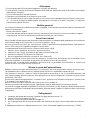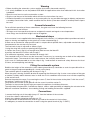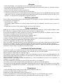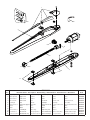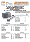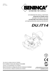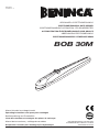
1
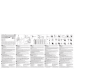
L8542904
10/2010 rev 2
APRICANCELLO ELETTROMECCANICO
ELECTROMECHANICAL GATE OPENER
ELEKTROMECHANISCHE AUTOMATION FÜR SCHIEBEGITTER
AUTOMATISATION ÉLECTROMÉCANIQUE POUR GRILLES
ABRECANCELA ELECTROMECANICO
ELEKTROMECHANICZNY OTWIERACZ BRAM
BOB 30M
Manual istruzioni e catalogo ricambi
Operating instructions and spare parts catalogue
Betriebsanleitung und Ersatzteilliste
Livret d’instructions et catalogue des pieces de rechange
Manual de instrucciones y catálogo de recambios
Książeczka z instrukcjami i katalog części wymiennych
UNIONE NAZIONALE COSTRUTTORI
AUTOMATISMI PER CANCELLI, PORTE
SERRANDE ED AFFINI
Dichiarazione CE di conformità per macchine
(Direttiva 98/37 CE, Allegato II, parte B)
Divieto di messa in servizio
Fabbricante: Automatismi Benincà SpA.
Indirizzo: Via Capitello, 45 - 36066 Sandrigo (VI) - Italia
Dichiara che: l’automazione per cancelli a battente modello BOB 30M.
• è costruito per essere incorporato in una macchina o per essere assemblato con altri macchinari per costituire una macchina considerata dalla Direttiva 98/37 CE, come modificata;
• non è dunque conforme in tutti i punti alle disposizioni di questa Direttiva;
• è conforme alle condizioni delle seguenti altre Direttive CE:
Direttiva bassa tensione 73/23/CEE, 93/68/CEE.
Direttiva compatibilità elettromagnetica 89/336/CEE, 93/68/CEE.
e inoltre dichiara che non è consentito mettere in servizio il macchinario fino a che la macchina in cui sarà incorporato o di cui diverrà
componente sia stata identificata e ne sia stata dichiarata la conformità alle condizioni della Direttiva 98/37 CE e alla legislazione
nazionale che la traspone, vale a dire fino a che il macchinario di cui alla presente dichiarazione non formi un complesso unico con
la macchina finale.
Benincà Luigi, Responsabile legale.
Sandrigo, 05/05/2010.
Declaration by the manufacturer
(Directive 98/37/EEC, Art. 4.2 and Annex II, sub B)
Divieto di messa in servizio
Manufacturer: Automatismi Benincà SpA.
Address: Via Capitello, 45 - 36066 Sandrigo (VI) - Italia
Herewith declares that: the operator for hinged gates model BOB 30M.
• is intended to be incorpored into machinery or to be assembled with other machinery to constitute machinery covered by Directive
98/37 EEC, as amended;
• does therefore not in every respect comply with the provisions of this Directive;
• does comply with the provisions of the following other EEC Directives:
Direttiva bassa tensione 73/23/CEE, 93/68/CEE.
Direttiva compatibilità elettromagnetica 89/336/CEE, 93/68/CEE.
and furthermore declares that it is not allowed to put the machinery into service until the machinery into which it is to be incorporated
or of which it is to be a component has been found and declared to be in conformity with the provisions of Directive 98/37/EEC and
with national implementing legislation, i.e. as a whole, including the machinery referred to in this declaration.
Benincà Luigi, Responsabile legale.
Sandrigo, 05/05/2010.
2
Herstellerklärung
(gemäß EG-Richtlinie 98/37/EWG, Artikel 4.2 und Anhang II, sub B.)
Verbot der Inbetriebnahme
Hersteller: Automatismi Benincà SpA.
Adresse: Via Capitello, 45 - 36066 Sandrigo (VI) - Italia
erklärt hiermit, daß: Antriebe für Drehflügeltore BOB 30M.
• vorgesehen ist zum Einbau in eine Maschine oder mit anderen Maschinen zu einer Maschine im Sinne der Richtlinie 98/37/EWG,
inklusive deren Änderunge, zusammengefügt werden soll;
• aus diesem Grunde nicht in allen Teilen den Bestimmungen dieser Richtlinie entspricht;
• den Bestimmungen der folgenden anderen EG-Richtlinien entspricht:
Direttiva bassa tensione 73/23/CEE, 93/68/CEE.
Direttiva compatibilità elettromagnetica 89/336/CEE, 93/68/CEE.
und erklärt des weiteren daß die Inbetriebnahme solange untersagt ist, bis die Maschine oder Anlage, in welche diese Maschine
eingebaut wird oder von welcher sie eine Komponente dasteilt, als Ganzes (d.h. inklusive der Maschine, für welche diese Erklärung
ausgesteilt wurde) den Bestimmungen der Richtlinie 98/37/EWG sowie dem entsprechenden nationalen Reschtserlaß zur Umsetzung
der Richtlinie in nationales Recht entspricht, und die entsprechende Konformitätserklärung ausgestellt ist.
Benincà Luigi, Responsabile legale.
Sandrigo, 05/05/2010.
Declaration du fabricant
(Directive 98/37/CEE, Article 4.2 et Annex II, Chapitre B)
Interdiction de mise en service
Fabricant: Automatismi Benincà SpA.
Adresse: Via Capitello, 45 - 36066 Sandrigo (VI) - Italia
Déclaire ci-apres que: l’automation pour portails ouvrants BOB 30M.
• est prévue pour être incorporée dans une machine ou être assemblée avec d’autres machines pour consituer une machine couverte
par la directive 98/37/CEE, modifiée;
• n’est donc pas conforme en tout point aux dispositions de cette directive;
• est conforme aux dispositions des directives CEE suivantes:
Direttiva bassa tensione 73/23/CEE, 93/68/CEE.
Direttiva compatibilità elettromagnetica 89/336/CEE, 93/68/CEE.
et déclare par ailleurs qu’il est interdit de mettre la machine en service avant que la machine dans laquelle elle sera incorporée ou
dont elle constitue une parte ait été considerée et declarée conforme aux dispositions de la Directive 98/37/CEE et aux législations
nationales la transposant, c’est-à-dire formant un ensemble incluant la machine concernée par la présente déclaration.
Benincà Luigi, Responsabile legale.
Sandrigo, 05/05/2010.
3
Declaración CE de conformidad para maquinas
(Directiva 98/37 CE, Apartado II, parte B)
Prohibición de puesta en servicio
Fabricante: Automatismi Benincà SpA.
Dirección: Via Capitello, 45 - 36066 Sandrigo (VI) - Italy
Declara que: la automatización para cancelas de batiente BOB 30M.
• está construída para ser incorporada en una máquina o para ser ensamblada con otras maquinarias para construir una máquina
considerada por la Directiva 98/37 CE, como modificada;
• no es, por consiguiente, conforme en todos los puntos a la posiciones de esta Directiva;
• es conforme a las condiciones de las siguientes otras Directivas CE:
Directiva de la baja tensión 73/23/CEE, 93/68/CEE.
Directiva de compatibilidad electromagnética 89/336/CEE, 93/68/CEE
además declara que no ha permitido poner en servicio la maquinaria hasta que la máquina en la cual será incorporada o de la cual
resultará componente esté identificada y no sea declarada la conformidad a las condiciones de la Directiva 98/37 CE y a la legislación
nacional que le corresponda, vale decir, hasta que la maquinaria correspondiente a la presente declaración no forme un conjunto único
con la máquina final.
Benincà Luigi, Responsable legal.
Sandrigo, 05/05/2010.
Deklaracja UE o zgodności z normami dla maszyn
(Wytyczna 98/37 UE, Załącznik II, Część B)
Zakaz użytkowania
Producent: Automatismi Benincà SpA.
Adres: Via Capitello, 45 - 36066 Sandrigo (VI) - Italia
Oświadcza że: Automatyzm do bram uchylnych model BOB 30M.
• został opracowany z myślą o wbudowaniu go do maszyny lub zmontowania z innymi urządzeniami w celu skonstruowania maszyny
uznanej przez Wytyczną 98/37 UE, za zmodyfikowaną;
• nie jest więc zgodny we wszystkich punktach z Wytyczną;
• jest natomiast zgodny z wymogami innych, poniżej wyszczególnionych, Wytycznych UE:
Wytyczna o niskim napięciu 73/23/EWG i 93/68/EWG
Wytyczna o zdolności współdziałania elektromagnetycznego 89/336/EWG, 93/68/EWG.
ponadto oświadcza, że zabronione jest stosowanie automatyzmu do czasu kiedy maszyna, do której ma być wbudowany lub stanowić
jej element składowy, nie uzyska świadectwa identyfikacyjnego oraz świadectwa orzekającego jej zgodność z wymogami Wytycznej
98/37 UE oraz z przepisami obowiązującymi w kraju sprowadzającym urządzenie, a więc do czasu kiedy automatyzm stanowiący
przedmiot niniejszego oświadczenia nie stanie się częścią składową urządzenia gotowego.
Benincà Luigi, Radca prawny
Sandrigo, 05/05/2010.
4
Dati tecnici
Technical data
Technische Daten
Donnees technique
Datos técnicos
Dane techniczne
Alimentazione
Power supply
Speisung
Alimentation
Alimentación
Zasilanie
Potenza assorbita
Absorbed rating
Leistung
Puissance absorbée
Potencia absorbida
Natężemie
Corrente assorbita
Absorbed current
Strom-Verbrauch
Courant absorbé
Corriente absorbida
Pobór mocy
Spinta
Thrust
Druck
Poussée
Par
Skok
Classe isolamento
Insulation class
BOB 30M
230 Vac
365 W
1.7 A
2300 N
Isolierklasse
Classe d'isolement
Clase de aislamiento
Klasa izolacji
Tempo per compiere 90° 90° rotation time
90° Öffnungszeit
Temps emp. pour 90°
Tiempo para abrir 90°
Prędkość kątowa dla 90°
Lunghezza max. anta
Max. wing length
Max. Flügellänge
Longueur max. porte
Longitud máx. hoja
Dł. max skrzydła bramy
Grado di protezione
Protection degree
Schutzgrad
Degré de protection
Grado de protección
Stopień ochrony
Velocità di traslazione
Translation speed
Geschwindigkeit
Vitesse de traslation
Velocidad traslacción
Prędkość przekładania
N° manovre consecutive
N° contin. manoeuvres
N. Vorgänge hintereinan.
N. manoeuvres conséc. N° maniobras consec.
Liczba kolejn. manewrów
10/15
Protezione termica
Thermal protection
Thermoschutz
Protection thermique Protección térmica
Ochrona termiczna
150°C
Laufzeit
Température de fonct.
Temperatura funcionam.
Temperatura przy pracy
Temper. funzionamento Operating temperature
F
≈ 19 s
3 m*
IP54
0,9m/1'
-20°C / +70°C
Rumorosità
Noise level
Geräuschentwicklung
Bruit
Ruido
Max. halas
<70 dB
Condensatore
Capacitor
Kondensator
Condensateur
Condensador
Kondensator
12,5 µF
Lubrificazione
Lubrication
Schmierung
Lubrification
Lubrificación
Smarowanie
Grasso Castrol
Optitemp LG2
Corsa standard
Standard stroke
Standardhub
Course standard
Carrera estancar
Posuw standard
Peso
Weight
Gewicht
Poids
Peso
Ciężar
270 mm
8,3 kg
* Vedi tabella 1 - See table 1 - Siehe Tabelle 1 - Voir tableau 1 - Ver cuadro 1 - Zobacz tabelę 1
TAB 1
Lunghezza anta / Door leaf width
Flügellänge / Longueur porte
Longitud hoja / Dł. skrzydła
(m)
Peso anta / Door leaf weight
Türflügelgewicht / Poids porte
Peso hoja / Ciężar skrzydła
(kg)
1
1,5
2
2,5
3
400
350
300
250
200
Dimensioni d’ingombro
Overall dimensions
Abmessungen
Dimensions d’encombrement
Dimensiones exteriores
Wymiary gabarytowe
796
107
62
132
47,5
270
Corsa.
Stroke.
Hub.
Course.
Carrera.
Posuw.
Mettere a livello.
Level.
Nivellieren.
Mettre de niveau.
Nivelar.
Ustawić na wysokości
Interasse ancoraggi.
Distance between axes of anchoring bolts.
Die maximale Öffnung der Verankerungen.
Entraxe ancrages.
Distancia entre ejes ancrajes.
Współośowość elementów mocujących.
660
88
Interasse ancoraggi.
Distance between axes of anchoring bolts.
Die maximale Öffnung der Verankerungen.
Entraxe ancrages.
Distancia entre ejes ancrajes.
Współośowość elementów mocujących.
5
Arresto in apertura.
Stop when opening.
Endanschlag zur Öffnung.
Arrêt en ouverture.
Tope en apertura.
Chwytak blokujący podczas otwierania.
Arresto in chiusura.
Stop when closing.
Endanschlag zur Schließung.
Arrêt en fermeture.
Tope de cierre.
Chwytak blokujący podczas zamykania.
Fig.1
X
K
M
Z
Y
P
S
X
Fig.2 - A
M
Y
90°
110°
max
Apertura max
Max Opening
Max. Öffung
Ouverture max
Abiertura max.
X
Y
Z
K
M*
max.
Tempo apertura
Opening time
Öffungszeit
Temps d'ouverture
Tiempo de abiertura
Prędkość kątowa
(90°)
110°
115
105
545
50
15"
100°
120
120
80
540
70
16"
90°
135
135
80
525
80
19"
90°
160
160
80
Fig.2
6
80
Dimensioni max anta
Max wing dimensions
Max Flügelmasse
Dimens. max de la porte
Dimens. max de la hoja
L(m)
P (kg)
1
300
1,3
200
1,8
150
1,8
200
2,1
150
2,1
200
V
B
P
V
Fig.3
B
F
C
T
Saldare.
Weld.
Anschweißen.
Souder.
Soldar.
Spawać
Rosetta 10x30.
Washer 10x30.
Unterlegscheibe 10x30.
Rondelle 10x30.
Arandela 10x30.
Podkładka 10x30.
Grasso
Grease
Fett
Graisse
Grasa
Smar
P
L
D
Mettere a livello.
Level.
Nivellieren.
Mettre de niveau.
Nivelar.
Ustawić na wysokości
S
Saldare.
Weld.
Anschweißen.
Souder.
Soldar.
Spawać.
R
V
Fig.4
7
Collegamenti
Connections
Kabelanschlüsse
Connexions
Conexiones
Podłączenia
���
Marcia motore e condensatore.
Motor gear and capacitor.
Motorgang und kondensator.
Marche moteur et condensateur.
Marcha motor y condensador.
Bieg silnika i praca kondensatora
Comune.
Common.
Mittell.
Commun.
Común.
Wspólny
Marcia motore e condensatore.
Motor gear and capacitor.
Motorgang und kondensator.
Marche moteur et condensateur.
Marcha motor y condensador.
Bieg silnika i praca kondensatora
G
Fig.5
Légende:
1 Moteur-réducteur BOB 30M
2 Photocellule FTC/FTM
3 Selecteur à clé CH (d’extérieur) ou clavier digital
4 Clignotant LAMP
5 Antenne AW
6 Centrale électronique SA.03 Head.
Leyenda:
1 Motorreductor BOB 30M
2 Fotocélulas FTC/FTM
3 Selectores a llave CH (de superficie).
4 Relampagueador LAMP.
5 AntenaAW.
6 Central electrónica SA.03 Head.
N.B.: Tenere separati i cavi di potenza da quelli ausiliari.
N.B.: The power cables must be kept separated from the auxiliary cables.
Wichtig: Leistungskabel von Hilfskabeln getrennt halten.
N.B.: Séparer les câbles de puissance des câbles auxiliaires.
N.B.: Tener separados los cables de potencia de los auxiliares.
Uwaga: należy trzymać w oddali przewody zasilania od przewodów pomocniczych.
5
3
4
2x1,5
2x1
RG 58
Objaśnienia:
1 Siłownik BOB 30M
2 Fotokomórki FTC/FTM
3 Przełącznik kluczowyCH (zewnętrzny) lub panel z
przyciskami
4 Światło migające LAMP
5 Antena AW
6 Centralka elektroniczna SA.03 Head
1
2x
1,5
4x
2
1
Legenda:
1 Motoriduttore BOB 30M
2 Fotocellule FTC/FTM
3 Selettore a chiave CH (da esterno) o tastiera digitale
4 Lampeggiante LAMP
5 Antenna AW
6 Centrale elettronica SA.03 Head.
Legenda:
1 Motoreducer BOB 30M
2 Photo-electric cells FTC/FTM
3 Key selector CH (external) or digital keyboard
4 Flash-light LAMP
5 Antenna AW
6 Electronic board SA.03 Head.
Zeichenerklärung:
1 Getriebemotor BOB 30M
2 Fotozelle FTC/FTM
3 Schlüssel-Selektor CH (außenliegend) oder Digital-Tastatur
4 Blinker LAMP
5 Antenne AW
6 Elektroschrank SA.03 Head.
8
1
1,5
4x
2
1
4x
n
mi
1,5 ac
x
3
0V
23
6
Attenzione
• Prima di procedere all’installazione leggere le istruzioni qui riportate.
• È fatto divieto assoluto di utilizzare il prodotto BOB 30M per applicazioni diverse da quelle contemplate
dalle presenti istruzioni.
• Istruire l’utilizzatore all’uso dell’impianto.
• Consegnare all’utilizzatore le istruzioni ad esso rivolte.
• Tutti i prodotti Benincà sono coperti da polizza assicurativa che risponde di eventuali danni a cose o perso- ne causati da difetti di fabbricazione, richiede però la marcatura CE della ”macchina” e l’utilizzo di
compo-nenti originali Benincà.
Notizie generali
Per un buon funzionamento delle automazioni in oggetto, il cancello da automatizzare dovrà rispondere alle
seguenti caratteristiche:
- buona robustezza e rigidità.
- le cerniere devono presentare giochi minimi e permettere che le manovre manuali siano dolci e regolari.
- in posizione di chiusura le ante devono combaciare fra loro per tutta l’altezza.
Arresti meccanici
Non essendo l'attuatore provvisto di finecorsa elettromagnetici, è indispensabile predisporre nel cancello da
automatizzare degli arresti meccanici in chiusura ed apertura. (fig.1)
Nel caso gli arresti meccanici non siano presenti e non sia possibile la loro predisposizione, è possibile utilizzare i fermi meccanici regolabili incorporati nell'attuatore.
La regolazione del fermo meccanico si effettua come segue (fig.3):
1 portare l'anta in posizione di massima apertura/chiusura
2 allentare la vite V (fig.3) quanto basta per poter muovere il blocco B
3 posizionare il blocco B in battuta con il perno P.
4 per una regolazione millimetrica ruotare di 180° il blocco B.
La corsa standard di 270mm può essere incrementata, se necessario, rimuovendo uno od entrambi i fermi
meccanici regolabili. La rimozione di ogni fermo incrementa la corsa di circa 30mm.
In questo caso è indispensabile predisporre gli arresti di fig.1 e prevedere una extracorsa di sicurezza di
almeno 5/10mm, sia in apertura sia in chiusura.
Messa in posa dell’automatismo
Stabilire l’altezza dal suolo dell’automatismo (si consiglia il più centrato possibile rispetto al portone ed in
corrispondenza di un solido traverso). Saldare quindi la piastra P rispettando le quote di fig. 2.
Con il portone in chiusura, saldare la staffa S rispettando la quota di fig. 3, ad un traverso del portone o ad
altro elemento adeguatamente robusto; tener presente che in questa condizione l'attuatore non deve essere
totalmente a fine corsa.
Rimuovere il coperchio di protezione C svitando la vite F, quindi fissare l’attuatore alla piastra P tramite la vite
T, la rondella L ed il dado D (fig. 3).
Bloccare infine l’attuatore alla piastra S tramite la vite V e la rondella R.
Le forature presenti nell'attuatore (fig.3A), agevolano il rispetto delle quote di installazione ottimali.
Le staffe di fissaggio regolabili, disponibili su richiesta, consentono una più ampia possibilità di adattamento
dell'attuatore alle diverse condizioni di installazione, evitando inoltre il taglio e la saldatura delle staffe fornite
in dotazione.
Collegamenti
1
2
3
4
rimuovere dal fondo dell'attuatore il dado di fissaggio del pressacavo "G".
inserire il cavo come indicato in Fig.5
bloccare il cavo serrando il dado di fissaggio "G".
per il collegamento alla centrale di comando, fare riferimento alla fig.5 e alle istruzioni della centrale stessa.
E' obbligatorio effettuare il collegamento di messa a terra utilizzando l'apposito morsetto (fig. 5 "GND").
9
Warning
• Before installing the automatic system read the instructions hereunder carefully.
• It is strictly forbidden to use the product BOB 30M for applications other than indicated in this instruction
handbook.
• Show the user how to use the automation system.
• Give the user the part of the leaflet which contains the instructions for users.
• All Benincá products are covered by an insurance policy for any possible damages to objects and persons
caused by construction faults, under condition that the entire system be marked CE and only Benincá parts
be used.
General information
For an efficient operation of these automatisms, the gate must have the following features:
- good stoutness and stiffness
- all hinges must have positive clearances and permit smooth and regular manual operations.
- when wings are closed their height have to fit together.
Mechanical stops
As the actuator is not supplied with electromagnetic limit switches, it is indispensable to provide mechanical
stops on closing and opening on the gate that is to be automated (fig.1)
If there are no mechanical stops present and it is not possible to provide them, adjustable mechanical stops
incorporated in the actuator may be used.
The mechanical stop is adjusted as follows (fig.3):
1 bring the wing into maximum opening/closing position
2 slacken the screw V (fig.3) just enough to be able to move the block B
3 position the block B in contact with the pin P.
4 for millimetre regulation, rotate the block B through 180°.
The standard travel of 270mm may be increased, if necessary, by removing one or both of the adjustable
mechanical stops. The removal of each stop increases the travel by about 30mm.
In this case it is indispensable to use the stops in fig. 1 and to allow an overtravel safety distance of at least
5/10mm, on both opening and closing.
Fitting the automatic system
Stabilise the height of the automatic system above ground level (it should be as central as possible with respect to the gate and corresponding to a sturdy cross piece).
Then weld the plate P respecting the distances in fig. 2.
When the gate is closing, weld the bracket S respecting the distance in fig. 3, onto a cross piece of the gate
or another suitably robust element; bear in mind that in this condition the actuator must not be completely
at the end of travel.
Remove the protective cover C unscrewing the screw F, then fix the actuator to the plate P with the screw T,
the washer L and the nut D (fig. 3).
Lastly block the actuator on the plate S with the screw V and the washer R.
The holes in the actuator (fig.3A) help you respect the optimum installation distances.
The adjustable fixing brackets, available on request, allow a wider possibility of adapting the actuator to the
different installation conditions, also avoiding cutting and welding the brackets supplied.
Connections
1 remove the fixing nut of the cable clamp “G” from the bottom of the actuator.
2 insert the cable as indicated in Fig.5
3 block the cable by tightening the fixing nut “G”.
4 for connection to the control unit, refer to fig.5 and to the control unit instructions.
It is obligatory to make the connection to earth using the special terminal (fig. 5 “GND”).
10
Achtung
• Vor Beginn der Montage diese Anleitungen lesen.
• Es ist stengstens untersagt, das Produkt BOB 30M für andere Zwecke zu verwenden, als die von den vorliegenden Anweisungen beschriebenen Anwendungszwecke.
• Den Benutzer über den Gebrauch der Anlage unterrichten.
• Dem Benutzer die Teile der Betriebsanleitung adgeben, die die auskunfte für den Benutzer enthaltet.
• Alle Produkte Benincà wurden mit einem Versicherungsschein versehen, der alle eventuellen Schäden an
Dingen oder Personen abdeckt, die durch Herstellungsdefekte hervorgerufen wurden, vorausgesetzt, das
Gerät besitzt die Kennzeichnung EU und es wurden original Benincà Einzelkomponenten verwendet.
Allgemeine Information
Zum guten Betrieb der genannten Automation, muß das Gitter folgende Eigenschaften haben:
- Stärke und Festigkeit
- Die Scharniere müssen minimale Spiele aufweisen und die manuelle Öffnung und Schließung müssen in
jedem Fall leicht sein.
- Bei der Schließung müssen die Flügel genau aufeinander passen
Mechanische Sperren
Da der Trieb über keine elektromagnetischen Endschalter verfügt, muss das zu automatisierende Tor an
Verschluss und Öffnung (Abb. 1) mit mechanischen Sperren versehen werden.
Falls keine derartigen mechanischen Sperren vorhanden sind oder nicht montiert werden können, besteht die
Möglichkeit zu diesem Zweck die im Trieb integrierten verstellbaren mechanischen Sperren zu verwenden.
Für die Einstellung der mechanischen Feststellvorrichtung wie folgt vorgehen (Abb. 3):
1 Den Torflügel auf die Position der maximalen Öffnung/Verschluss bringen.
2 Die Schraube V (Abb.3) soweit lockern, dass die Sperre B bewegt werden kann
3 Die Sperre B am Bolzen P in Anschlag bringen.
4 Für eine millimetrische Einstellung die Sperre B um 180° drehen.
Der Standardhub von 270 mm kann, falls erforderlich, erhöht werden, indem eine oder beide verstellbaren
mechanischen Sperren entfernt werden. Das Entfernen einer Sperre erhöht den Hub um zirka 30 mm.
In diesem Fall müssen unbedingt die Feststellvorrichtungen der Abb. 1 verwendet und ein Sicherheits-Überlauf
von mindestens 5/10 mm bei Öffnen und Schließen vorgesehen werden.
Installation der Torautomatisierung
Den Bodenabstand der Torautomatisierung bestimmen (so weit wie möglich mit dem Tor zentriert und auf
Höhe eines soliden Querträgers).
Nun unter Einhaltung der Quoten der Abb. 2 die Platte P schweißen.
Bei geschlossenem Tor den Bügel S unter Einhaltung der Quote der Abb. 3 an einem Querträger des Tors
oder an einem anderen ausreichend robusten Element anschweißen; in diesem Zustand darf der Trieb sich
nicht ganz am Endanschlag befinden.
Die Schrauben F aufschrauben und die Schutzkappe C entfernen; dann den Trieb mit den Schrauben T, der
Unterlegscheibe L und der Mutter D (Abb. 3) an der Platte P befestigen.
Zuletzt den Trieb mit der Schraube V und der Unterlegscheibe R an der Platte S befestigen.
Die Bohrungen am Trieb (Abb. 3A) vereinfachen die Einhaltung der optimalen Installationsquoten.
Die auf Anfrage erhältlichen verstellbaren Bügel erhöhen die Anpassbarkeit des Triebs an die unterschiedlichen
Montagebedingungen und vermeiden das Zuschneiden und Schweißen der mitgelieferten Bügel.
Anschlüsse
1
2
3
4
Die Haltemutter der Kabelklemme „G“ vom Boden des Triebs ausbauen.
Das Kabel gemäß der Angaben der Abb. 5 einführen.
Das Kabel durch Festziehen der Haltemutter „G“ fixieren.
Für den Anschluss an die Steuerzentrale wird auf die Abb. 5 und auf die Gebrauchsanweisung der Zentrale
selbst verwiesen.
Die Erdung mittels der speziellen Klemme (Abb.5 „GND“) ist obligatorisch vorgeschrieben.
11
Attention
• Avant de procéder à l’installation, lire les instructions contenues dans ce manuel.
• Il est impérativement interdit d’utiliser le produit BOB 30M pour des applications différentes de celles énoncées dans les présentes instructions.
• Fornir à l’utilisateur les renseignements sur l’emploi de l’installation.
• Donner à l’utilisateur la partie du livret d’instructions qui contiens les renseignements pour l’utilisateur.
• Tous les produits Benincà sont couverts par une police d’assurance qui répond d’éventuels préjudices
corporels ou matériels provoqués à cause de défauts de fabrication, mais qui requiert toutefois le marquage
CE de la “machine” et l’utilisation de pièces de rechange d’origine Benincà.
Notice générales
Pour un bon fonctionnement de l’automatisme en object, la porte basculante doit avoir les suivantes caractéristiques:
- bonne robustesse et rigidité
- les charniéres doivent avoir un moindre jeu pour permettre que les manoeuvres soient aisées et réguliéres.
- en position de fermeture, les portes doivent parfaitement coïncider entre elles et sur toute la hauteur.
Butées mécaniques
Le vérin n’étant pas muni de fins de course électromagnétiques, il est indispensable de prévoir dans le portail
à automatiser des butées mécaniques en fermeture et en ouverture. (fig. 1)
Si les butées mécaniques ne sont pas présentes et qu’il n’est pas possible de prévoir leur installation, on peut
utiliser les butées mécaniques réglables incorporées dans le vérin.
Le réglage de la butée mécanique s’effectue de la façon suivante (fig. 3):
1 mettre le vantail en position d’ouverture/fermeture maximum
2 desserrer la vis V (fig. 3) de manière à pouvoir bouger le dispositif de blocage B
3 positionner le dispositif de blocage B en butée contre le pivot P.
4 pour un réglage millimétrique tourner de 180° le dispositif de blocage B.
La course standard de 270 mm peut être augmentée, si nécessaire, en enlevant l’une ou les deux butées
mécaniques réglables. L’enlèvement de chaque butée augmente la course d’environ 30 mm.
Dans ce cas, il est indispensable de prévoir les arrêts de la fig. 1 et de régler une surcourse de sécurité d’au
moins 5/10 mm, aussi bien en ouverture qu’en fermeture.
Mise en place de l’automatisme
Établir la hauteur de l’automatisme par rapport au sol (il est conseillé de choisir la position la plus centrale
possible par rapport au portail et correspondant à une traverse solide).
Souder ensuite la platine P en respectant les cotes de la fig. 2.
Avec le portail en fermeture et en respectant la cote de la fig. 3, souder la patte S à une traverse du portail
ou à un autre élément suffisamment robuste ; tenir compte du fait que dans cette condition le vérin ne doit
pas être totalement en fin de course.
Enlever le couvercle de protection C en dévissant la vis F puis fixer le vérin à la platine P avec la vis T, la
rondelle L et l’écrou D (fig. 3).
Pour finir, bloquer le vérin à la platine S avec la vis V et la rondelle R.
Les trous présents sur le vérin (fig. 3A), facilitent le respect des distances d’installation idéales.
Les pattes de fixation réglables, disponibles sur demande, permettent une plus ample possibilité d’adaptation
du vérin aux différentes conditions d’installation, en évitant par ailleurs de devoir couper et souder les pattes
incluses dans la fourniture.
Connexions
1
2
3
4
enlever du fond du vérin l’écrou de fixation du serre-câble «G».
introduire le câble comme l’indique la Fig.5
bloquer le câble en serrant l’écrou de fixation «G».
pour la connexion à la logique de commande, se référer à la fig. 5 et aux instructions de la logique de commande proprement dite.
Il est obligatoire d’effectuer la connexion de la mise à la terre en utilisant la borne prévue à cet usage (fig. 5
«GND»).
12
Atención
• Antes de proceder a la instalación leer las instrucciones aquí aportadas.
• Está absolutamente prohibido utilizar el producto BOB 30M para aplicaciones diversas a aquellas contempladas en las presentes instrucciones.
• Instruir al usuario sobre el uso de la instalación.
• Entregar al usuario las instrucciones que le corresponden.
• Todos los productos Benincà están cubiertos por la póliza de seguros que responde de eventuales daños
a personas o cosas causados por defectos de fabricación, pero require para ello la marca CE de la ”maquinaria” y la utilización de componentes originales Benincà.
Noticias generales
Para un buen funcionamiento de las automatizaciones en cuestión, la cancela a automatizar deberá responder
a las siguientes características:
- Buena robustez y rigidez
- Las bisagras deben presentar un mínimo juego y permitir que las maniobras manuales sean suaves y regulares.
- En posición cerrada las hojas deben quedar al mismo nivel en altura.
Topes mecánicos
Dado que el actuador no está provisto de fines de carrera electromagnéticos, resulta imprescindible instalar
en la cancela a automatizar topes mecánicos para el cierre y la apertura (fig.1).
Si no están montados los topes mecánicos y de no ser posible su instalación, se podrán utilizar los topes
mecánicos ajustables con que está provisto el actuador.
Para regular el tope mecánico hay que hacer lo siguiente (fig.3):
1 poner la puerta en posición de máxima apertura/cierre
2 aflojar el tornillo V (fig.3) lo que sea necesario para poder mover el dispositivo de bloqueo B
3 posicionar el dispositivo de bloqueo B apoyado al perno P.
4 para una regulación milimétrica, girar 180º el bloque B.
De ser necesario, se puede aumentar la carrera estándar de 270mm, y para ello se desmonta uno de los topes
mecánicos ajustables o los dos. El desmontaje de cada tope incrementa la carrera de cerca de 30mm.
En este caso es imprescindible preparar los topes de la fig.1 y prever un sobrerrecorrido de seguridad de por
lo menos 5/10mm, tanto en la apertura como en el cierre.
Instalación del automatismo
Establecer la altura con respecto al suelo a la que tiene que estar el automatismo (es conveniente que esté
lo más centrado posible respecto del portón y que coincida con un travesaño sólido).
Soldar la placa P respetando las cotas de la fig. 2.
Con el portón cerrado, soldar el estribo S con la cota indicada en la fig. 3, en un travesaño del portón o en
otro elemento adecuadamente resistente. Hay que tener en cuenta que en esta situación el actuador no se
hallará totalmente en fin de carrera.
Quitar el tornillo F, desmontar la tapa de protección C y fijar el actuador en la placa P con el tornillo T, la
arandela L y la tuerca D (fig. 3).
Por último, bloquear el actuador en la placa S con el tornillo V y la arandela R.
Los orificios del actuador (fig.3A) facilitan el respeto de las cotas de instalación óptimas.
Los estribos de fijación regulables, disponibles sobre demanda, permiten al actuador adaptarse mucho mejor
a las diferentes condiciones de instalación, y se evita además cortar y soldar los estribos suministrados en
equipamiento.
Conexiones
1 quitar del fondo del actuador la tuerca de fijación del prensacable “G”
2 insertar el cable como se indica en la fig. 5
3 bloquear el cable apretando la tuerca de fijación “G”
4 para la conexión con la central de mando, consultar la fig. 5 y las instrucciones de la central.
Es obligatorio efectuar la conexión de tierra utilizando el borne pertinente (fig. 5 “GND”).
13
Uwaga
· Przed przystąpieniem do instalacji należy uważnie przeczytać przytoczone poniżej instrukcje.
· Zabronione jest jakiekolwiek stosowanie produktu BOB 30M do celów odmiennych od wymienionych w
niniejszych instrukcjach.
· Należy pouczyć użytkownika o sposobie użytkowania urządzenia.
· Dostarczyć użytkownikowi przeznaczone dla niego instrukcje.
· Wszytkie produkty Beninca’, oznakowane znakiem CE dla „maszyn” i składające się z oryginalnych części
Beninca’, objęte są polisą ubezpieczeniową na pokrycie szkód poniesionych przez rzeczy lub osoby w
wyniku wad produkcyjnych.
Informacje ogólne
Aby automatyzmy o których mowa mogły należycie funkcjonować, brama musi spełniać następujące
warunki:
- musi posiadać odpowiednio gruby i sztywny pancerz
- zamki mogą wykazywać jedynie minimalny luz i muszą umożliwiać łagodne i regularne wykonywanie
manewrów ręcznych
- podczas zamknięcia bramy, skrzydła muszą dokładnie przylegać do siebie na całej wysokości.
Blokady mechaniczne
W sytuacjach gdy napęd nie posiada elektromagnetycznej krańcówki posuwu, niezbędne jest zastosowanie
w bramach przeznaczonych do automatyzacji mechanicznych blokad dla zamykania i otwierania. (rys.1)
W przypadku braku blokad mechanicznych oraz braku możliwości ich zastosowania, można zastąpić je
mechanicznymi, nadającymi się regulować chwytakami blokującymi już wbudowanymi w napęd.
Regulacji mechanicznego chwytaka blokującego dokonuje się w poniżej podany sposób (rys.3):
1 otworzyć/zamknąć całkowicie skrzydło bramy
2 zluzować śrubę V (rys.3) tak by umożliwić poruszanie chwytakiem B
3 ustawić chwytak blokujący B w miejscu zderzania się ze sworzniem P.
4 dla regulacji millimetrowej przekręcić o 180° chwytak blokujący B.
Posuw standardowy wynoszący 270mm może zostać zwiększony, jeśli zachodzi taka potrzeba, przez usunięcie
jednej lub obydwu regulowalnych blokad mechanicznych. Usunięcie każdej z blokad zwiększa posuw o około
30mm.
W danym przypadku nieodzowne jest założenie zatrzymywaczy wskazanych na rys.1 i zapewnienie, z
racji na bezpieczeństwo, posuwu extra wynoszącego co najmniej 5/10mm, zarówno w otwieraniu jak i w
zamykaniu.
Montowanie automatyzmu
Ustalić dla automatyzmu poziom wysokości od nawierzchni jego podłoża (zaleca się w punkcie możliwie
najbardziej centralnym względem bramy i stosownym do jednego z solidnych trawersów).
Następnie przyspawać płytę P zachowując poziomy wskazywane na rys. 2.
Podczas zamkniętej bramy przyspawać pętlę S, zachowując poziom wskazywany na rys. 3, do jednego z
trawersów bramy lub do innego odpowiednio wytrzymałego elementu; należy pamiętać że w takiej sytuacji
napęd nie może całkiem znajdować się na krańcówce ograniczania posuwu.
Zdjąć nakrywkę ochronną C odkręcając śrubę F, następnie przymocować napęd do płyty P za pomocą śruby
T, podkładki L i nakrętki D (rys. 3).
Na koniec unieruchomić napęd przytwierdzony do płyty S poprzez śrubę V i podkładkę R.
Otwory istniejące w napędzie (rys.3A), ułatwiają zachowanie optymalnych poziomów wysokości dla
instalacji
Regulowane pętle mocujące, dostępne na zamówienie, dają większą możliwość przystosowania napędu do
różnych warunków instalacji, z wykluczeniem również cięcia i spawania pętli z wyposażenia dodatkowego.
Połączenia
1
2
3
4
zdjąć z krawędzi napędu nakrętkę mocującą dławik „G”.
wpuścić przewód jak wskazuje Rys.5
unieruchomić przewód dokręcając nakrętkę mocującą „G”.
odnośnie połączeń z centralą sterującą, należy opierać się przykładach podanych na rys.5 i na instrukcji
dla tejże centrali.
Obowiązkowe jest wykonanie uziemienia stosując odpowiedni zacisk (rys. 5 „GND”).
14
1
10
8
2
7
5
9
4
6
3
11
11
BOB 30M
Pos.
1
2
3
4
5
6
7
8
9
10
11
Denominazione - Description - Bezeichnung - Dénomination - Denominación - Określenie
Coperture plast.
Plastic covers
Plastikabdeckungen
Couvertures plastique Cubierta de plástico
Obudowy Plastykowe
Carter superiore
Upper cover
Gehäuse
Carter
Cárter
Karter
Carter inferiore
Lower cover
Gehäuse
Carter
Cárter
Karter
Vite senza fine
Worm screw
Welle
Vis sans fin
Tornillo sin fin
Śruba dwustronna
Ingranaggio
Gear
Zahnrad
Engranage
Engranaje
Koło zębate
Supporto vite s.f.
Wormscrew support WelleStütze
Support vis sans fin
Soporte tornillo sin fin
Zaczep śruba dwustronna
Motore
Motor
Motor
Moteur
Motor
Silnik
Blister
Blister
Blister
Blister
Blister
Blister
Perno di sblocco
Lock with pin
Entblockung
Plaque avec pivot
Bloqueo
Chwytak blok. NY ze sworzn.
Leva di sblocco
Release lever
Entriegelungshebel
Levier de déblocage
Palanca de desbloq.
Dźwignia odblokowująca
1 Tope mecánico
1 Blokady mechaniczne
1 Fermo meccanico 1 Mechanical stop
1 Mechanische Sperren 1 butée mécanique
Cod.
9686868
9686869
9686870
9686819
9686820
9686816
9686874
9686817
9686876
9686877
9686818
15
Libro istruzioni per l’utilizzatore
BOB
Norme di sicurezza
• Non sostare nella zona di movimento delle ante.
• Non lasciare che i bambini giochino con i comandi o in prossimità delle ante.
• In caso di anomalie di funzionamento non tentare di riparare il guasto ma avvertire un tecnico specializzato.
Manovra manuale e d’emergenza
In caso di mancanza dell’energia elettrica o di guasto, per azionare manualmente le ante procedere come
segue (riferirsi alle figure A,B,C):
• Aprire lo sportellino di protezione del meccanismo di sblocco (fig. A).
• Inserire la speciale chiave di sblocco fornita in dotazione e ruotarla di 90°, come indicato in fig. B per un
attuatore destro o come indicato in fig. C per un attuatore sinistro.
• È ora possibile aprire/chiudere manualmente l'anta.
• Per ripristinare il funzionamento automatico, riportare la chiave di sblocco nella posizione iniziale.
• Rimuovere la leva di sblocco e richiudere lo sportellino di protezione.
Manutenzione
• Controllare periodicamente l’efficienza dello sblocco manuale di emergenza.
• Astenersi assolutamente dal tentativo di effettuare riparazioni, potreste incorrere in incidenti; per queste
operazioni contattare un tecnico specializzato.
• L’attuatore non richiede manutenzioni ordinarie, tuttavia è necessario verificare periodicamente l’efficienza
dei dispositivi di sicurezza e le altre parti dell’impianto che potrebbero creare pericoli in seguito ad usura.
Smaltimento
Qualora il prodotto venga posto fuori servizio, è necessario seguire le disposizioni legislative in vigore al
momento per quanto riguarda lo smaltimento differenziato ed il riciclaggio dei vari componenti (metalli, plastiche, cavi elettrici, ecc.); è consigliabile contattare il vostro installatore o una ditta specializzata ed abilitata
allo scopo.
Attenzione
Tutti i prodotti Benincà sono coperti da polizza assicurativa che risponde di eventuali danni a cose o persone
causati da difetti di fabbricazione, richiede però la marcatura CE della ”macchina” e l’utilizzo di componenti
originali Benincà.
Fig.A
Fig.B
Fig.C
S
L
L
16
BOB
User’s handbook
Safety rules
• Do not stand in the movement area of the gate.
• Do not let children play with controls and near the gate.
• Should operating faults occur, do not attempt to repair the fault but call a qualified technician.
Manual and emergency manoeuvre
In the event of a power cut or breakdown, proceed as follows to operate the wings manually (refer to figures
A,B,C):
• Open the protective door of the release mechanism (fig. A).
• Insert the special release key supplied and turn it through 90°, as indicated in fig. B for a right actuator or
as indicated in fig. C for a left actuator.
• It is now possible to open/close the wing manually.
• To restore automatic operation, return the release key to its initial position.
• Remove the release lever and close the protective door.
Maintenance
• Every month check the good operation of the emergency manual release.
• It is mandatory not to carry out extraordinary maintenance or repairs as accidents may be caused.These
operations must be carried out by qualified personnel only.
• The operator is maintenance free but it is necessary to check periodically if the safety devices and the other
components of the automation system work properly. Wear and tear of some components could cause
dangers.
Waste disposal
If the product must be dismantled, it must be disposed according to regulations in force regarding the differentiated waste disposal and the recycling of components (metals, plastics, electric cables, etc..). For this
operation it is advisable to call your installer or a specialised company.
Warning
All Benincá products are covered by insurance policy for any possible damages to objects and persons
caused by construction faults under condition that the entire system be marked CE and only Benincá parts
be used.
Fig.A
Fig.B
Fig.C
S
L
L
17
Handbuch für den Verbraucher
BOB
Sicherheitsvorschriften
• Nicht im Öffnungsbereich verweilen.
• Kinder nicht mit den Steuerungen oder in der Nähe des Tores spielen lassen.
• Bei Funktionsausfällen nicht versuchen, den Schaden selber zu beheben, sondern den Techniker rufen.
Manuelle Bedienung und Notbetrieb
Um das Tor im Falle eines Stromausfalls oder einer Betriebsstörung von Hand betätigen zu können, die Entriegelung wie folgt einsetzen (siehe Abbildungen A, B, C):
• Die Schutzabdeckung des Entriegelungsmechanismus öffnen (Abb. A).
• Den mitgelieferten, speziellen Entriegelungsschlüssel einstecken und um 90° drehen, und zwar wie in der
Abb. B gezeigt, für rechtsseitige Triebe, oder wie in der Abb. C gezeigt, für linksseitige Triebe.
• Nun kann der Torflügel von Hand geöffnet oder geschlossen werden.
• Um den automatischen Betrieb wieder herzustellen, den Entriegelungsschlüssel wieder auf die Ausgangsposition bringen.
• Den Entriegelungshebel entfernen und die Schutzabdeckung wieder verschließen.
Wartung
• Monatliche Kontrolle der manuellen Notentriegelung
• Es ist absolut untersagt, selbstständig Sonderwartung oder Reparaturen vorzunehmen, da Unfälle die Folge
sein können; wenden Sie sich an den Techniker.
• Der Antrieb braucht keine ordentliche Unterhaltung aber es ist periodisch notwendig die Leistungsfähigkeit
der Sicherheitsvorrichtungen und die andere Teile des Anlages zu prüfen. Sie könnten durch Abnutzung
Gefaht hervorbringen.
Entsorgung
Wird das Gerät außer Betrieb gesetzt, müssen die gültigen Gesetzesvorschriften zur differenzierten Entsorgung
und Wiederverwendung der Einzelkomponenten, wie Metall, Plastik, Elektrokabel, usw., beachtet werden.
Rufen Sie Ihren Installateur oder eine Entsorgungsfirma.
Achtung
Alle Produkte BENINCA’ wurden mit einem Versicherungsschein versehen, der alle eventuellen Schäden an
Dingen oder Personen abdeckt, die durch Herstellungsdefekte hervorgerufen wurden, vorausgesetzt, das
Gerät besitzt die Kennzeichnung EU und es wurden original BENINCA’ Einzelkomponenten verwendet.
Fig.A
Fig.B
Fig.C
S
L
L
18
BOB
Manuel d’instructions pour l’utilisateur
Normes de sécurité
• Ne vous arrêtez jamais dans la zone de mouvement des portes.
• Ne laissez pas les enfants jouer avec les commandes ou à proximité des portes.
• En cas d’anomalies de fonctionnement, n’essayez pas de réparer la panne mais contactez un technicien
spécialisé.
Manœuvre manuelle et d’urgence
En cas de coupure de courant ou de panne, pour actionner manuellement les vantaux, procéder de la façon
suivante (se référer aux figures A,B,C) :
• Ouvrir la petite porte de protection du mécanisme de déblocage (fig. A).
• Introduire la clé de déblocage spéciale incluse dans la fourniture et la tourner de 90°, comme l’indique la
fig. B pour un vérin droit ou comme l’indique la fig. C pour un vérin gauche.
• Il est maintenant possible d’ouvrir et de fermer manuellement le vantail.
• Pour rétablir le fonctionnement automatique, reporter la clé de déblocage dans la position initiale.
• Enlever le levier de déblocage et refermer la porte de protection.
Maintenance
• Contrôler tous les mois le bon état du déverrouilleur manuel d’urgence.
• S’abstenir impérativement de toute tentative d’effectuer des maintenances extraordinaires ou des réparations, sous risque d’accident. Contactez un technicien spécialisé pour ces opérations.
• L’actuateur ne demande pas de manutention ordinaire mais il faut verifier periodiquement l’efficience des
dispositifs de sécurité et les autres parties de l’installation qui puissent créer dangers à cause d’usure.
Démolition
Au cas où le produit serait mis hors service, il est impératif de se conformer aux lois en vigueur pour ce qui
concerne l’élimination différenciée et le recyclage des différents composants (métaux, matières plastiques
câbles électriques, etc...) contactez votre installateur ou une firme spécialisée autorisée à cet effet.
Attention
Tous les produits Benincà sont couverts par une police d’assurance qui répond d’éventuels préjudices corporels ou matériels provoqués à cause de défauts de fabrication, mais qui requiert toutefois le marquage CE
de la “machine” et l’utilisation de pièces de rechange d’origine Benincà.
Fig.A
Fig.B
Fig.C
S
L
L
19
Manual de instrucciones para el usuario
BOB
Normas de seguridad
• No pararse en la zona de movimiento de las hojas.
• No dejar que los niños jueguen con los mando o en proximidad de las hojas.
• En caso de anomalías de funcionamiento no intentar reparar la avería sino que avisar a un técnico especializado.
Maniobra manual y de emergencia
De fallar el suministro de energía eléctrica o en caso de avería y para accionar manualmente las puertas, hay
que hacer lo siguiente (tener como referencia las figuras A,B,C):
• Abrir la portezuela de protección del mecanismo de desbloqueo (fig. A).
• Insertar la llave de desbloqueo especial suministrada en equipamiento y girarla 90°, como se indica en la
fig. B para un actuador derecho o como se indica en la fig. C para un actuador izquierdo.
• Ahora se puede abrir /cerrar la puerta manualmente.
• Para restablecer el funcionamiento automático, volver a poner la llave de desbloqueo en su posición original.
• Quitar la palanca de desbloqueo y cerrar la portezuela de protección.
Mantenimiento
• Controlar periódicamente la eficiencia del desbloqueo manual de emergencia.
• Abstenerse absolutamente de intentar efectuar reparaciones, podrían incurrir en accidentes; para estas
operaciones contactar con un técnico especializado.
• El operador no requiere mantenimiento habitual, no obstante es necesario verificar periódicamente la eficiencia de los dispositivos de seguridad y las otras partes de la instalación que pudiesen crear peligros a
causa del desgaste.
Eliminación de aguas sucias
Cada vez que el producto esté fuera de servicio, es necesario seguir las disposiciones legislativas en vigor
en ese momento en cuanto concierne a la eliminación de suciedad y al reciclaje de varios componentes
(metales, plásticos, cables eléctricos, etc.), es aconsejable contactar con su instalador o con una empresa
especializada y habilitada para tal fin.
Atención
Todos los productos Benincà están cubiertos por una póliza de seguros que responde de eventuales daños a
personas o cosas, causados por defectos de fabricación, requiere sin embargo la marca CE de la ”máquina”
y la utilización de componentes originales Benincà.
Fig.A
Fig.B
Fig.C
S
L
L
20
BOB
Książeczka z instrukcjami dla użytkownika
Normy bezpieczeństwa
• Starać się nie przebywać w obszarze posuwu skrzydeł.
• Niedopuścić aby dzieci bawiły się sterownikami lub w pobliżu skrzydeł bramy.
• W przypadku niewłaściwego funkcjonowania nie starać się samemu dokonywać naprawy a powiadomić o
fakcie technika wyspecjalizowanego.
Sterowanie ręczne i awaryjne
W przypadku braku dopływu energii elektrycznej podczas awarii, dla ręcznego sterowania skrzydeł bramy należy
postępować według poniższych wskazówek (opierać się na przykładach podanych na rysunkach A,B,C):
• Otworzyć drzwiczki ochronne mechanizmu odblokowującego (rys. A).
• Wprowadzić specialny klucz odblokowujący dostarczony razem z wyposażeniem dodatkowym i przekręcić
go o 90°, jak wskazuje rys. B dla napędu prawego lub jak wskazuje rys. C dla napędu lewego.
• W tym momencie możliwe już jest ręczne otwieranie/zamykanie skrzydła bramy.
• W celu przywrócenia funkcjonowania automatycznego, należy przestawić klucz odblokowujący do pozycji
początkowej.
• Usunąć dźwignię odblokowującą i zamknąć drzwiczki ochronne.
Konserwacja
• Sprawdzać okresowo sprawność działania ręcznego mechanizmu odblokowującego i bezpieczeństwa.
• Nie starać się w żadnym wypadku dokonywać napraw samemu z racji na możliwość ulegnięcia wypadkowi,
w celu naprawy należy skontaktować się z technikiem wyspecjalizowanym.
• Siłownik nie wymaga normalnej konserwacji, tym niemniej wskazane jest okresowe sprawdzanie sprawności
działania elementów bezpieczeństwa i pozostałych części instalacji, mogących stanowić zagrożenie z racji
na stan zużycia.
Eliminacja i demolowanie
W przypadku gdy urządzenie nie nadaje się już do dalszego użytkowania, w celu pozbycia się go należy ściśle
przestrzegać obowiązujących w danym momencie norm prawnych regulujących zróżnicowany rozkład na
części i odzyskiwanie niektórych elementów składowych (metale, plastyk, kable elektryczne, itp.); wskazane
jest skontaktowanie się z instalatorem lub wyspecjalizowaną firmą, autoryzowaną do tego rodzaju prac.
Uwaga
Wszystkie produkty Benincà objęte są polisą ubezpieczeniową na pokrycie szkód poniesionych przez rzeczy
lub osoby w wyniku wad produkcyjnych, pod warunkiem że urządzenia posiadają oznakowanie CE i oryginalne
części Benincà.
Fig.A
Fig.B
Fig.C
S
L
L
21
AUTOMATISMI BENINCÀ SpA - Via Capitello, 45 - 36066 Sandrigo (VI) - Tel. 0444 751030 r.a. - Fax 0444 759728