1
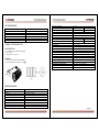
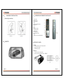
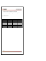
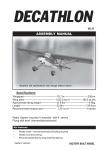
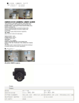
CARACTERÍSTICAS
MANUAL DE INSTRUCCIONES
MONITOR TFT LCD PARA RETROVISOR DE AUTOMÓVIL
CTV-1129
•
•
•
•
•
Pantalla TFT-LCD y reproductor VCD/DVD
Sustituto de lente óptico para el retrovisor.
Se activa automáticamente cuando el coche está retrocediendo.
Fondo de pantalla azul automático cuando no hay señal de video.
Dispositivo con ranuras que facilitan la instalación y la desinstalación.
INSTALACIÓN
•
•
•
Le recomendamos que la instalación sea realizada por un técnico calificado.
Si el monitor no funciona correctamente, revise primero las conexiones y luego el fusible.
Una instalación inadecuada del monitor puede provocar que las baterías se derramen o que se
produzca un corto circuito.
CONDENSACIÓN
Cuando la temperatura del ambiente desciende significativamente, es posible que se forme
condensación dentro del monitor y es necesario que espere unos minutos para que la humedad se
evapore antes de volver a usar el equipo.
Ante cualquier consulta sobre este equipo, consulte con su distribuidor.
CUIDADOS DEL CONTROL REMOTO
•
No coloque el control remoto sobre el tablero del automóvil, el volante u otro lugar donde quede
expuesto a la luz directa del sol, especialmente en verano ya que la temperatura puede deformar el
control remoto.
•
Cuando deje el automóvil parqueado, coloque el control remoto en la guantera u otro lugar seguro.
•
La señal del control remoto falla cuando está bajo la luz directa del sol. Debe colocarlo cerca del
inductor del panel frontal
SOBRE LA PANTALLA LCD
•
No presione la pantalla LCD ya que podría distorsionarla o dañarla y la imagen será borrosa.
LIMPIEZA
Use un paño suave húmedo para limpiar la pantalla.
No use solventes como gasolina, thinner, limpiadores químicos o agentes antiestáticos.
No use este aparato en temperaturas inferiores a los -20ºC o superiores a los 65ºC.
ESTIMADO CLIENTE
Felicitaciones por su compra!
Por favor lea cuidadosamente este manual, y guárdelo para su futura referencia.
Si necesita soporte adicional, no dude en escribir a: [email protected]
•
Si estaciona el automóvil en un lugar muy caliente, la imagen no será clara y volverá al estado
normal una vez que la temperatura se normalice.
•
Los pequeños puntos rojos o azules que podrían aparecer en el monitor, llamados puntos
luminosos, es un fenómeno normal en los equipos LCD. Este es un dispositivo de alta precisión y
más del 99% de los segmentos son normales, sin embargo menos del 0.01% podrían tener
imperfecciones, lo cual no afecta la imagen.
Pagina 1
CABLEADO
Cable rojo conectado al polo positivo +12V
CONTROL REMOTO
Cable blanco a tierra
Cable verde conectado a la lámpara de retroceso
1. Botón de Encendido
2.Selector de Canal
3.Ajuste de Canal
4.Menu
5.ajuste de volumen
6. Selector de Modo
7.Botón Call
8.Temporizador (timer)
9.Revsersa (derecha / izquierda)
10.Reversea (arriba / Abajo)
11.Busqueda automática
12.Selector de idioma
13.Interruptor TV/AV1/AV2
14.Mute
15.Cubierta de las baterias (”AAA”X2,
Video AV1 conectado al VDC/DVD
Video AV2 conectado a la cámara
CONEXIÓN DE LA CÁMARA
Cable amarillo conectado al video AV2
Cable negro conectado al cable de
energía de la cámara
DIAGRAMA DE INSTALACIÓN
no incluidas)
REMPLAZO DE LAS BATERÍAS
En condiciones normales la batería tiene una duración de 1 año (o menos, dependiendo del uso).
Cuando la distancia de operación disminuye significa que la batería está por agotarse.
MONITOR
ACERCA DE LAS BATERÍAS DE LITIO
• Mantenga las baterías lejos del alcance de los niños. En caso de que un niño se trague la batería
busque atención médica de inmediato.
• Limpie las baterías con un paño seco para asegurar que haya buen contacto.
• Observe la polaridad cuando instale las baterías.
• No use objetos metálicos para sostener las baterías para evitar corto circuitos.
CUIDADO
El uso inadecuado de las baterías puede causar que estas exploten. No cargue las baterías, no las
desarme ni las arroje al fuego.
INSTALACIÓN DE LAS BATERÍAS
•
•
•
Pagina 2
Retire el soporte de la batería presionando el seguro y tirándolo hacia fuera.
Coloque la nueva batería en el soporte con el lado positivo (+) hacia arriba.
Vuelva a introducir el soporte de la batería hasta su posición original.
Pagina 3
LISTA DE EMPAQUE
Unidad central
Control remoto
Cable externo
Cable de video
Manual de instrucciones
Control de calidad
Cámara
1
1
1
1
1
1
1 (Opcional)
CÁMARA A PRUEBA DE AGUA
CARACTERÍSTICAS
1. A prueba de agua con cubierta súper resistente
2. Visión nocturna
3. Distancia del IR: 1 a 3 metros
CONEXIÓN
1. Conecte el cable amarillo a la entrada de video.
2. Conecte la energía a la entrada DC 12 V
Dispositivo de imagen
Sistema de televisión
Píxels efectivos
Área sensible
Sistema de escaneo
Sistema de muestreo
Resolución
Frecuencia de muestreo horizontal
Frecuencia de muestreo vertical
Iluminación mínima
Salida de video
Consumo Gama
AGC
Relación señal/ruido
Balance de blanco
Disparador electrónico
BLC
Consumo de energía
Fuente de energía
Temperatura de operación
Temperatura de almacenamiento
Lente
Ángulo de lente
OV7910
PAL
NTSC
628 x 582 píxels
510 x 492 píxels
5.78mm X 4.19mm
4.69mm X 3.54mm
Interlace 2.1
Interno
380 líneas de TV
15.625 KHz
15.734 KHz
50 Hz
60 Hz
0 Lux
10Vp-p. 75Ohm
0.45
Auto
Menos de 48dB
Automático
1/50 (PAL) o 1/60 (NTSC) ~ 1/15.000 segundos
Auto
Max. 200mA
DC 12V
-10ºC ~ 46ºC, H.R 95% Máximo
-30ºC ~ 60ºC, H.R. 95% Máximo
f=3.6mm/F=2.0
92º
ESPECIFICACIONES
Dispositivo
Tamaño de la pantalla
Resolución
Sistemas
Voltaje
Consumo de energía
Método de control
Utilidad
Rango de temperatura de uso
Función
Pagina 4
Ranura para tarjeta
TFT color de 7 pulgadas
1440 (ancho) x 234 (Alto)
PAL/NTSC
9-15V (cable rojo: positivo, cable negro: negativo)
7 watts máximo
Botones / Control remoto
Monitor para vehículo y para entretenimiento
-20ºC /+65ºC
Función de retrosivor automático cuando retrocede
Pagina 5
I! SPECIFICATION
INSTRUCTION MANUAL
CAR BACK-VIEW TFT LCD MONITOR
CTV-1129
Model
Device
Screen size
Definition
System
Nominal voltage
Power consumption
Way of control
Purpose
Working environment
Display function
CTV-1129
Card slot
7"color TFT
1440(W)x234(H)
PAL/NTSC
9-15V,red line;positive;black line;negative
7W MAX
Push button/Remote controller
Monitor and vehicle entertainment
-20 ~+65
Auto reversing back-view shift (mirror)
II! FEATURES
1.TFT-LCD DISPLAY AND PLAY VCD/DVD
2.Special optical lens substitute the original Back-view Mirror
3.Automatially shift back-view system when reversing the car
4.Automatially wake up reversing Back-view display
5.Blue color background automatically appears when video signal disappears
6.Slot device simplifies installation and detachment.
III!
ON INSTALLATION
1. We strongly recommend have qualified technician or maintenance engineer install this device.
2. If this monitor does not work well,check the connection first,then the fuse if it the connection is ok.
DEAR CUSTOMER
3. Improper installation of this MONITOR may cause battery leakage or short circuit.
Congratulations for your purchase!
Please read this manual carefully, and keep it for future reference.
If you need extra support, please write to [email protected]
Pagina 1
IV! DEWING
When environmental temperature declines dramatically,dew may occurinside the monitor,user need
wait for a minute till the moisture vapors,then the device will return to good condition.
Do not use this product when environmental temperature is lower than-20 or higher
than+65
3.If you park your car in an extremely cold or hot place,the video may become unclear,it is not a
fault,When the temperature in car returns to normal level,the video will become clear.
If you have any query or question about this machine,please consult your nearest
dealer.
4. Static blue or red spot may appear on the monitor,this called light spot,it is a common
phenomenon for any kind of LCD.LCD is a very precise device,more than 99.99% segment is
normal,but less than 0.01% segment may be flaw,however,this will not affect your visual
V! ADDITIONAL INFORMATION
effects.
Precautions of remote controller
1.DO not place the remote controller on dashboard,steering wheel or any other place under direct
VI! CONNECTION AND INSTALLATION
sunlight especially in summer,where there is high tempearture which may deform the remote
controller.
Red wire connects anode+12V
Black wire grounde
Green wire connects to reversing lamp 12V
Video AV1connects VCD/DVD signal input
Video AV2 connects camera signal input
2.When paking the car in the sun,please place the card-style remote controller in toolkit or other
safe places.
3.When exposed in direct sunlight,signal emitting from the remote controller may not be properly
received by the monitor.It should be place nearer to the inductor of frontal panel of the host.
ON LCD
1.DO not press the screen of LCD,otherwise distortion of other fault may occur.the image may
become unclear or LCD may be damaged.
2.Precautions of cleaning
Connection of camera
Yellow wire connects video AV2
Black wire connects power cord of
camera
Uses a little wet soft cloth to clean the screen.
Do not use solvent such as gasoline,thinner,cleaner in the market or anti static spray to clean
the screen.
Pagina 2
Pagina 3
VII!
DIAGRAM OF INSTALLATION:
IX! OPERATIONS OF REMOTE CONTROLLER
(See the figure bellow)
Figure(1)
VIII! MONITOR
Figure(2)
1. Power on/off
2.Channel celect
3.Channel adjust
4.Menu
5.Volumn increase/decrease
6.Mode select
7.Call
8.Timer
9.Left/Right reverse
10.Up/Down reverse
11.Auto search
12.Language select
13.TV/AV1/AV2 switch
14.Mute
15.Battery cover (”AAA”X2,EXCLUDE)
WATERPROOF CAMERA
FEATURE
1. Waterproof without extra housing needed.
2. Night vision available.
3. IR distance:1M~3M.
OPERATION
1. Yellow socket is for video output.
2. Power socket is connected to DC12V.
Pagina 4
Pagina 5
Image Device
TV System
Effective Pixels
Sensing Area
Scanning System
Sync.System
Resolution
Horizontal Sync Frequency
Vertical Sync Frequency
Minimum Illumination
Video Output
Gamma Consumption
AGC
S/N Ratio
White Balance
Electyonic Shutter
BLC
Current Consumption
Power Supply
Operating Tempurature
Storage Tempurature
Lens
Lens Angle
Ov7910
PAL
NTSC
628X582 pixels
510X492pixels
5.78mmX4.19mm
4.96mmX3.54mm
2:1Interlace
Interlace
380TV lines
15,625kHz
15,734kHz
50Hz
60Hz
0Lux
1.0Vp-p,75!
0.45
Auto
Better than 48dB
Auto
1/50(PAL)or1/60(NTSC)~1/15,000 Second
Auto
Max:200mA
DC12V
-10 ~46 ,RH95%MAX
-30 ~60 ,RH95%MAX
f=3.6mm/F=2.0
92°
2. Funtions
a) On backing the car,the rear camera and sensor work automatically,The screen will show the
condition behind car.
b) The screen shows the distance between the car and obstacles within 3.0m number,If obstacles are
on the left,the arrow on the left of screen will flash.So as to obstacles on the right.
c) The
visible
Reversing
RadarSystem
is
combined
with
ultraso
connect VCD/DVD player,the other is active during reversing car and indicate character ;there are 2
video outlets well,and one is video output,the other,audio output .The distance between the rear of
car and obstacle is detected by the ultrasonic detector installed on the rear,meanwhile,the camera
indicate the object image on the monitor.You can judge the safe distance vary with the
alarm,distance(in digital on TFT,unit meter),and the image,so as to avoid knock,and create a safe
park environment for you.
3.Conecting Method of power wires
Instruction for Parking Sensor with TV Screen Display
1. Introdution
The TV screen visible indicating system consists of a mainframe, a buzzer,a distance
display,rear-camera and 24 ultrasonic sensors,It is the perfect combination of the ultrasonic
distance-measuring technology with microcomputer and visible code addition technology.The
driver could watch the conditions in rear of the car through screen.Also,on backing the car,the
screen will show the condition behind the car and obstacles,meanwhile,the word of “stop”
appears on it with sound alarm.
Pagina 6
nic
detector,camera(selectrable),TFT(selectable),processing unit.One of the 2 video input cables can
1
Pagina 7
4. Radar Main Function
Image monitor range
2video input ,1video output
Active once reverse gear work
Standard video signal output to external monitor
Number (unit:meter) ind icate the the distance from obstacle
Simulating strip indicate dire ction of left/right
10 level simu lating strip indicate distance from obstacle
Voice alarm
2/3/4 sensors
3
External or internal ultrasonic derector selectable
Various direction cameras selectable
5. Technical Specifications:
Rating Voltage: DC 12V (DC24V)
Working vokage range:DC10.5V~16V;DC16V~28V
Rating current :200mA~1100mA
Detecting distance:0.30m-2.00m
Ultrasonic frequency: 40KHz
Alarm mode
Working temperature range:-30~+85!
Ultraonic detection range
2
Pagina 8
Level
Dist from obstacle
Zone type
Alarm voice
Dist(unit:m)idicated
1
2
3
4
5
6
7
8
200cm
150cm
120cm
100cm
80cm
60cm
50cm
40~0cm
Safe zone
Safe zone
Safe zone
Alarm zone
Alarm zone
Alarm zone
Danger zone
Danger zone
2m
1.5m
1.2m
1m
0.8m
0.6m
0.5m
Brake
2.0
1.5
1.2
1
0.8
0.6
0.5
0
Simulation
strip
1
4
5
6
7
8
9
10
Pagina 9
Detoctor Installation Instruction
Indicating Status
Safe zone
Outer-set affixed detector instruction
Alarm zone
Ensure detector location,there shall be not obstacle
Within side sight at 90!,otherwise,false alarm occurs.
0.5"0.8m
Inner-set affixed detector installation instruction
Danger zone
4
The best installation location of 2 detectors
Pagina 10
5
6
Pagina 11
Instruction:
1. Outer-stuck detector apply original imported 3M one-off double-sided tape,affixed
Inner-set detector camera hole instruction
area shall be clean.The adhesive ability will reach the best effect in 48 hours since
the object is affixed.
2. Shielded cable may not be cut or punched;
3. Sensor shall be installed in the hole drilled on the bumper(See pic:7) ;
4. The direction of detector shall be correct(see pic:8)
5. The arrow mark on the shell of the camera shall be upward,before installation,the
7
detedtion direction shall be adjusted in electrification state.
Detector installation direction instrution
11
8
Digital contronl box is installed in the
trunk,the location shall be safe,not
hot;not
damp;not
aplashed,not
shakable ,not interfered.
Slippery slops
Offer various streamline camera
9
Not detectable object
Pagina 12
Slippery ball
The layout of the cable shall
be invisible & good-lloking
Sound-absorb object
ddobjobject
12
Pagina 13
Installation adjustment&test procedure
c. If there still is problem,it’s sure that the detector is defective or detector is not
complying with digital box,whole unit shall be replaced.
1. After detector installation,adjust the direction of detector,and arrange the cable smoothly.
2. Connect the red cable of processing unit and cam era to the poaotive polarity of rear light;the
black,negative polarity;(please refer to installation instruction)
3. Connect the video cable following installation instruction.
Note:The program of the product:if the detecting range is within 0.3m,TFT will
indicate”0.0” for alarm purpose,requesting the driver to stop the car.In this casek,no
distance will be showed.If the range is within 0.5m,the alarm will be time-lagged 1sec.
upon cancel.
precautions
4. Video-in 2# cable and video-out cable are connected when power is off or the car is not
backed;
5. The system will act upon back gear working,signals captured by camera (V-in 1#)will be
output after attaching distance digital(V-out).There should be image and a white pointin
TFT,indication that the reversing radar is working.
Check methods:
a. If there is no image in TFT,please check if the polarity of power supply is correct and the
power supply is well connected.And check if the voltage is over 9V,or the TFT connector
is well plugged.
b. If there is inregullar character or “0.0” indicated in TFT or buzz is heard,please recover the
backing gear and ty again if the pheomenon is the same,the processing unit shall be
detfective;the whole unit shall be replaced.
6. The detector shall same the one who within 1.3 m in the right front.
a. If detector is plugged into digital box,buzz is heared,and indicate “0.0”,user shall check if
there is obstacle in front or by the side.And if the detector is too tight or located in heavy
1. The size of camera and hole of sensor shall be same.
2. While installing the ultrasonic detector,the car engins must be power off.
3. In wet weather of the water flow into detector,or on unevea road,send land,slope,or in too
hot/cold/wet or day,or the detector is covered by mud,snow or is feezing,the results will be
affected.
4. Any change of ultrasonic / electric wave,DC and AC,24V and 12V etc.maybe affect detection
result.
5. Detector shall be fittec with installation.
6. If the detector is installed on iron bumper,maybe the result is affected.
7. Digital box shall keep away from interference location,such as exhaust,wire layout etc.
8. Operation direction shall be tested before utinization.
9. This product is just for alarm;should amy accident occurs,it beyond our company’s
responsibility.
vibration/interference place(such as exhaust,wire layout etc.)
b. If some value is indicated and there is no obstacle in the front or the sidea,maybe it
detected the ground.Please check the direction and of detector and axis.The axis of
detector shall be slope up a litle.Maybe it caused by project item(such as license
plate,apare tire,bumper etc.)
6.Attention
a) on hearing continuous sound, the driver should stop the car for the distance detection doesn’t
activate to the brake devices of the car.
b) However speed should be kept in backing to avoid colliding with obstacles in parking
operation due to inertia.
Pagina 14
Pagina 15
c) Remove such substances as ice, snow and mud from the sensor timely.
d) Avoid flatting, perforating, cutting and extending the wires of sensors during installation.
X! PACKAGING LIST
SN
1
2
3
4
5
6
7
8
9
Pagina 16
NAMES
HOST
Remote controller
Cxternal wire
Video wire
User’s Manual
Warrant Card
Pass Certificate
camera
radar
QUANTITY
1
1
1
1
1
1
1
1
1set
REMARKS
Optional