1
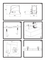
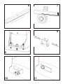
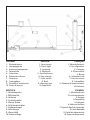
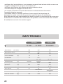
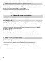
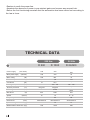
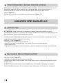
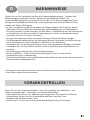
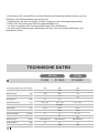
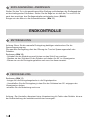
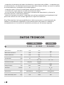
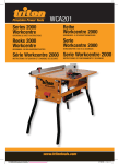
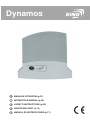
Dynamos I MANUALE ISTRUZIONI (p.01) GB INSTRUCTION MANUAL (p.05) F LIVRET D’INSTRUCTIONS (p.09) D ANLEITUNGS HEFT (a.13) E MANUAL DE INSTRUCCIONES (p.17) 1 274 94 325 185 2 3 4 5 7 2mm 6 9 8 10 11 )4!,)!./ -OTORIDUTTORE ,AMPEGGIANTE !NTENNAINCORPORATA &OTOCELLULA #OLONNINA 3ELETTOREACHIAVE &INECORSA #REMAGLIERA #ARTELLODIAVVERTENZA &ERMIDgARRESTO $%543#( Antriebsmotor Blitzleuchte Antenne Lichtschranke Kleine Säule Schlüsselschalter %NDLAGENBàGEL :AHNSTANGE 7ARNSCHILD %NDANSCHLËGE %.',)3( 'EARMOTOR &LASHLIGHT !NTENNA 0HOTOCELL 3MALLCOLUMM +EYSELECTOR ,IMITSWITCH 2ACK 7ARNINGSIGN 3TOPLOCKS &2!.!)3 -OTORÏDUCTEURS &EUCLIGNOTANT !NTENNE 0HOTOCELLULE "ORNE 3ÏLECTEURÌCLÏ &INSDECOURSE #RÏMAILLÒRE 0ANNEAUDgAVERTISSEMENT !RRÐTOIRS %30!/, -OTORREDUCTOR ,UZINTERMITENTE !NTENA &OTOCÏLULA #OLUMNA 3ELECTORDELLAVE 4OPEDEFINALDERECORRIDO #ARRILDENTADO #ARTELDEADVERTENCIA 4OPESDEDETENCIØN I MODELLI Codice Dynamos 500 Descrizione Irreversibile 230 Vac con centrale incorporata e ricevitore 433.92 Mhz, max 500 kg Dynamos 500 PLUS Irreversibile 230 Vac con centrale incorporata, sistema encoder e ricevitore 433.92 Mhz, max 500 kg Dynamos 1000 Irreversibile 230 Vac con centrale incorporata e ricevitore 433.92 Mhz, max 1000 kg Dynamos 1000 PLUS Irreversibile 230 Vac con centrale incorporata, sistema encoder e ricevitore 433.92 Mhz, max 1000 kg Dynamos 24/600 Irreversibile 24 Vdc con centrale incorporata e ricevitore 433.92 Mhz, max 600 kg GB AVAILABLE VERSION Code Description Dynamos 500 Irreversible 230 Vac, incorporate control unit and radio receiver 433.92 Mhz, max 500 kg Irreversible 230 Vac, incorporate control unit, encoder system and radio receiver 433.92 Mhz, max 500 kg Dynamos 500 PLUS Dynamos 1000 Irreversible 230 Vac, incorporate control unit and radio receiver 433.92 Mhz, max 1000 kg Dynamos 1000 PLUS Irreversible 230 Vac, incorporate control unit, encoder system and radio receiver 433.92 Mhz, max 1000 kg Dynamos 24/600 Irreversible 24 Vdc, incorporate control unit and radio receiver 433.92 MHz, inside buffer batteries (optional), max 600kg F MODELE Code Description Dynamos 500 Irréversible 230 Vac avec centrale incorporée et récepteur 433.92 Mhz, max 500 kg Dynamos 500 PLUS Irréversible 230 Vac avec centrale incorporée système encoder et récepteur 433.92 Mhz, max 500 kg Dynamos 1000 Irréversible 230 Vac avec centrale incorporée et récepteur 433.92 Mhz, max 1000 kg Dynamos 1000 PLUS Irréversible 230 Vac avec centrale incorporée système encoder et récepteur 433.92 Mhz, max 1000 kg Dynamos 24/600 Irréversible 24 Vdc avec centrale incorporée et récepteur 433.92 Mhz, max 600 kg D VERFÜGBARE VERSIONEN Bezeichnung Ausführung Dynamos 500 Selbsthemmender elektromechanischer Antrieb 230Vac mit integrierter Steuerung und Funkempfänger 433,92Mhz, max.500kg Torgewicht Dynamos 500 PLUS Selbsthemmender elektromechanischer Antrieb 230Vac mit integrierter Steuerung, Encoder System und Funkempfänger 433,92Mhz , max.500kg Torgewicht Dynamos 1000 Selbsthemmender elektromechanischer Antrieb 230V mit integrierter Steuerung und Funkempfänger 433,92Mhz , max.1000kg Torgewicht Dynamos 1000 PLUS Selbsthemmender elektromechanischer Antrieb 230V mit integrierter Steuerung, Encoder System und Funkempfänger 433,92Mhz , max.1000kg Torgewicht Dynamos 24/600 Selbsthemmender elektromechanischer Antrieb 24V mit integrierter Steuerung und Funkempfänger 433,92Mhz , max.600kg Torgewicht E MODELOS Código Descripción Dynamos 500 Irreversible 230 V ca con central incorporada y receptor de 433,92 MHz, máximo de 500 kg Dynamos 500 PLUS Irreversible 230 V ca con central incorporada, sistema encoder y receptor de 433,92 MHz, máximo de 500 kg Dynamos 1000 Irreversible 230 V ca con central incorporada y receptor de 433,92 MHz, máximo de 1000 kg Dynamos 1000 PLUS Irreversible 230 V ca con central incorporada, sistema encoder y receptor de 433,92 MHz, máximo de 1000 kg Dynamos 24/600 Irreversible 24V dc con central incorporada y receptor de 433,92 MHz, máximo de 500 kg I AVVERTENZE Prima di procedere all'installazione verificare che siano presenti tutte le condizioni di sicurezza per operare nel pieno rispetto dI leggi, norme e regolamenti. Utilizzare i dispositivi di sicurezza personale e predisporre cartelli informativi sulla presenza di cancello motorizzato. La non osservanza delle sotto elencate disposizioni solleva la ditta Antoniolli Mario & s.a.s., titolare del marchio King gates (in seguito King gates) da ogni responsabilità per danni causati a persone e cose. -All'apertura dell'imballo verificare che il prodotto sia integro. -In caso di anomalie nel funzionamento spegnere subito il motoriduttore, togliere l'alimentazione elettrica e gestire il cancello manualmente finché non si è individuato ed eliminato il guasto. -Non eseguire modifiche su nessuna parte del prodotto, se non prevista nel manuale. -Lo smontaggio dell'apparecchio va eseguito esclusivamente da personale autorizzato e qualificato. -Evitare che le parti dell'automatismo vengano poste vicino a fonti di calore o a contatto con sostanze liquide. -Servirsi di cavi di alimentazione adeguati. -Per un funzionamento ideale dell'automatismo utilizzare accessori King gates. -L'installazione, il collaudo e la messa in funzione devono essere eseguite secondo la normativa vigente. -Smaltire i materiali di rifiuto nel rispetto della normativa locale. -Il motoriduttore non necessita di manutenzione in quanto viene fornito con una lubrificazione a grasso permanente. ATTENZIONE: L'installazione dovrà essere effettuata esclusivamente da personale qualificato secondo normative vigenti VERIFICHE PRELIMINARI Prima di procedere all'installazione, è necessario leggere attentamente tutte le istruzioni che forniscono importanti indicazioni riguardanti la sicurezza, l'installazione, l'uso e la manutenzione. -accertarsi che la struttura del cancello sia solida ed appropriata. -verificare che il cancello sia adatto ad essere automatizzato con la tipologia di motoriduttore scelto. -verificare che il cancello sia ben bilanciato, che durante la corsa non presenti sbandamenti e che il sistema ruote-rotaie non subisca attriti. -verificare la presenza e la robustezza dei fermi di arresto. 1 -verificare che il motoriduttore e i vari accessori vengano fissati su basi solide, su zone non soggette ad allagamenti e al riparo da eventuali urti. -verificare che l'accesso allo sblocco manuale sia facile e sicuro. -ricordarsi sempre di collegare la linea di terra. -nei cancelli preesistenti accertarsi dell'assenza di alimentazione ed eliminare l'eventuale serratura manuale. -prima della messa in funzione verificare di aver eseguito l'automazione del serramento in modo concorde alle normative vigenti nel paese di installazione. King Gates declina ogni responsabilità per danni a persone o cose avvenuti per cause non direttamente riconducibili alle caratteristiche del prodotto e all'inosservanza delle modalità di installazione secondo le normative vigenti. DATI TECNICI 230 Vac Alimentazione (Vac 50Hz) Alimentazione motore 24 Vdc D 500 D 1000 D 24/600 230 230 230 230 230 24 Potenza motore (W) 200 400 70 Corrente assorbita (A) 1,3 1,9 1.8 (µF) 10 12,5 - Temperatura di esercizio (°C) -20 ÷ +55 -20 ÷ +55 -20 ÷ +55 Termoprotezione (°C) integrata integrata - Livello di protezione (IP) IP 44 IP 44 IP 44 Condensatore Spinta max. Velocità Ciclo di lavoro Dimensioni (N) 550 1000 550 (m/min) 10 10 9 ÷ 15 (%) 30 30 80 325x185x274 325x185x274 325x185x274 (mm) Peso automatismo (Kg) 10 12 11 Peso max. cancello (Kg) 500 1000 600 2 INSTALLAZIONE E' indispensabile leggere attentamente le istruzioni prima di procedere all'installazione. Si declina ogni responsabilità per eventuali danni e malfunzionamenti derivanti dall'inosservanza delle istruzioni e da errori di collegamento che potrebbero compromettere la sicurezza o il corretto funzionamento del motoriduttore. I FISSAGGIO PIASTRA Serrare i due tiranti di fondazione sulla piastra con i due dadi M10 (fig.2). Facendo riferimento alle misure di ingombro fissare a terra la piastra in una base di calcestruzzo di adeguate dimensioni, rispettando le quote di fissaggio, parallela al cancello e perfettamente in bolla. Prevedere una o più guaine per il passaggio dei cavi elettrici (fig.3). A basamento solidificato allentare i dadi, posizionare il motoriduttore sulla piastra di fondazione verificando che sia perfettamente parallelo al cancello e riavvitare leggermente i due dadi in dotazione (fig.4). FISSAGGIO CREMAGLIERA Posizionare il motoriduttore sul funzionamento manuale (fig.10). Portare l'anta del cancello in completa apertura. Predisporre la cremagliera, appoggiare il primo elemento al pignone e bloccarlo con viti M6 al cancello (fig.5). Spostare manualmente l'anta e ripetere l'operazione con gli altri elementi utilizzando uno spessore che faccia da contro-cremagliera e ne permetta il corretto posizionamento (fig.6). E' consigliabile lasciare uno spazio di 2 mm tra cremagliera e ingranaggio in modo che il peso del cancello non gravi sul motoriduttore (fig.7). REGOLAZIONE FINALE Per la regolazione finale in altezza tra cremagliera e motore utilizzare i 4 grani posizionati sulle alette per un'altezza non superiore ai 15 mm (fig.8). Fissaggio definitivo del motoriduttore stringendo i 2 dadi posizionati sui tiranti di fondazione. 3 POSIZIONAMENTO STAFFE FINE CORSA Portare l'anta in apertura / chiusura. Fissare le staffe di finecorsa dx e sx sulla cremagliera con gli appositi grani, considerando che nella fase di arresto il cancello scorre per altri 2-3 cm dopo l'intervento del finecorsa (fig.9). Ripristinare il motore sul funzionamento automatico (fig.11). MANOVRA MANUALE SBLOCCO ATTENZIONE: Prima di eseguire la manovra manuale del motoriduttore togliere l'eventuale alimentazione. Il motore viene tuttavia disattivato nel momento dello sblocco grazie alla presenza di un microinterruttore di sicurezza. La manovra di sblocco è stata prevista per l'apertura manuale del cancello in caso di mancanza di corrente o di avaria del motore. ISTRUZIONI (fig.10). -Far scorrere all'indietro il copri serratura. -Inserire la chiave nell'apposito cilindro e ruotarla in senso orario di 90°. -Tirare a se' la maniglia fino a portarla in posizione perpendicolare al motoriduttore. RIPRISTINO AUTOMAZIONE ISTRUZIONI (fig.11). -Riportare la maniglia nella posizione originale. -Inserire la chiave nell' apposito cilindro e ruotarla in senso antiorario di 90°. ATTENZIONE: Si declina ogni responsabilità per eventuali danni o malfunzionamenti derivanti dall' inosservanza delle istruzioni o da errori di collegamento. 4 GB WARNINGS Before installing the product ascertain that safety conditions are observed according to the law, rules and regulation. Use personal safety devices and locate warning signs on the motorized gate. Unfulfilment of the below listed direction will release the Antoniolli Mario & C. sas, holder of the KING gates mark, from any responsibility for damage caused to people or things. -Ascertain the intigrity of the packing when opening it. -In case of anomalies in the functioning, turn immediatly off the gear-motor, disconnect electrical power and operate the gate manually the problem has been found and salved. -Do not modify the product in any part. -Only authorized and qualified staff is alloned to disassemble the product. -Prevent any part of the automation from being next to any source of heat or in contact with liquid substances. -Use only adeguate power supply cables. -To optimize the functioning of the automation, King gates accessories only. -Disposal of waste material has to observe local regulations. -Installing, testing and first functioning have to observe the laws in force. -The gear-motor doesn’t require any maintenance because provided with a permament lubrification system. ATTENTION: Only authorized and qualified staff can to install the product according to the law in force. PRELIMINARY CONTROL Before installing the product, read carefully the instructions whic provide guidelines about safety, installment, use and maintenance. -Ascertain the solidity and appropriateness of the gate’s frame. -Ascertain the compatibility of the gate with the selected gear-motor. -Ascertain the good balance of the gate. -Ascertain the presence and good working condition of stopping devices. -Ascertain that the gear-motor and the accessories are fixed on stable surfaces, protected from flooding and being hit. -Ensure an easy and safe access to the manual release system. 5 -Rember to earth the power line. -Ascertain the absence of power in pre-existent gates and remove any manual lock. -Before the first functioning ascertain that the automation has been carried out according to the law in force. TECHNICAL DATA 230 Vac 24 Vdc D 500 D 1000 D 24/600 (Vac 50Hz) 230 230 230 (Vac/Vdc) 230 230 24 Motor rating (W) 200 400 70 Electrical input (A) 1,3 1,9 1.8 Condenser (µF) 10 12,5 - Working temperature (°C) -20 ÷ +55 -20 ÷ +55 -20 ÷ +55 Thermic protection (°C) integrata integrata - IP/Rating (IP) IP 44 IP 44 IP 44 Max thrust (N) 550 1000 550 (m/min) 10 10 9 ÷ 15 (%) 30 30 80 325x185x274 325x185x274 325x185x274 10 12 11 500 1000 600 Power supply Motor power supply Speed Frequency of use Dimensions Operator weight (mm) (Kg) Maximumdoor dimension (Kg) 6 INSTALLATION Read the instructions with care before installing the product. The producer disclains all responsibility for any damage or bad functioning caused by non-osservance of the instructions or bad connection that may result in poor safety and functioning of the gear-motor. GB PLATE FIXING Tighten the two foundation tie-beans on the plate with the two M10 nuts (pic.2) In accordance with the size, fix the plate on a concrete base of adeguate dimension, complying with fixing distances which have to be vertical and parallel to the gate. Arrange one or more sheaths for electric cables (pic.3). Once the base has hardened, loose the nuts, place the gear-motor on the foundation plate ascertaining it is parallel to the gate, and gently tighten the two nuts provided (pic.4). RACK FIXING Set the gear-motor on manual functioning (pic.10). Wide open the gate’s door. Place the rack, place the first element on the pinion and fix it with M6 screws to the gate (pic.5) Move the door manually and repeat the procedure with the other elements using a distance spacer to ensure the correct position from the rack (pic.6). It is advisable to leave 2mm between the rack the gear to avoid the gate resting on the gear-motor (pic.7). FINAL ADJUSTMENT For the final height adjustment between the motor and the rack, use the 4 screws located on the external sides for a height up to 15mm (pic.8). The final fixing of the gear-motor is done by tightening the 2 nuts placed on the foundation tie/beans. 7 STOPPING STIRRUPS INSTALLING Move the door to open/close position. Fix the left and right stop-stirrups on the rack with the screws provided, considering that when stopping, the gate slides for 2/3 cm more after the limit switch intervenes (pic.9). Set the motor authomatic functioning (pic.11). MANUAL CONTROL RELEASE ATTENTION: before operating the manual release disconnect the power. The motor is anyway disconnected during the release, thanks to the presence of a safety micro-switch. Manual control has been thought for manual opening of the gate in case of power-cut or motor breakdown. Instruction (pic.10). -Operate the manual release moving back the key hole cover. -Insert the key in the cylinder lock and turn it of 90° clockwise direction. -Pull the lever till it is perpendicular to the gear-motor. RESTORATION Instruction (pic.11). -Bring back the lever in the original position. -Insert the key in the cylinder lock and turn it of 90° anticlockwise direction. ATTENTION: the producer disclaims all responsibility for any damage or bad functioning caused by non-observance of the instructions or bad connection. 8 F AVERTISSEMENTS Avant de procéder à l'installation vérifier que toutes les conditions de sécurité pour travailler dans le respect des lois, normes et règlements sont appliquées. Utiliser les dispositifs de sécurité du personnel et prédisposer les panneaux d'information sur la présence d'un portail motorisé. L'inobservation des dispositions listées ci-dessous décharge l'entreprise Antoniolli Mario & SCS., propriétaire de la marque King gates (ci-après King gates) de toute responsabilité pour les dommages causés à des personnes ou des objets. -A l'ouverture de l'emballage vérifier que le produit est intègre. -En cas d'anomalie dans le fonctionnement éteindre immédiatement le motoréducteur, couper l'alimentation électrique et gérer le portail manuellement jusqu'à ce que la panne soit déterminée et éliminée. -N'effectuer de modifications sur aucune pièce du produit, si elle n'est pas prévue dans le manuel. -Le démontage de l'appareil doit être effectué exclusivement par du personnel autorisé et qualifié. -Eviter que les pièces de l'automatisme soient placées près de sources de chaleurs ou en contact avec des substances liquides. -se servir de câbles d'alimentation adaptés. -Pour un fonctionnement idéal de l'automatisme utiliser les accessoires King gates. -L'installation, le contrôle et la mise en marche doivent être effectués selon la norme en vigueur. -Eliminer les matériaux de déchets dans le respect de la norme locale. -Le motoréducteur ne nécessite pas d'entretien étant donné qu'il est fourni avec une lubrification à graisse permanente. ATTENTION: L'installation devra être effectuée exclusivement par du personnel qualifié selon les normes en vigueur VERIFICATIONS PRELIMINAIRES Avant de procéder à l'installation, il est nécessaire de lire attentivement toutes les instructions qui fournissent d'importantes indications concernant la sécurité, l'installation, l'usage et l'entretien. -s'assurer que la structure du portail est solide et appropriée. -vérifier que le portail est adapté pour être automatisé ave la typologie de motoréducteur choisi. 9 -vérifier que le portail est bien équilibré, que durant la course il ne présente pas d'inclinaison et que le système roues/rails ne subit pas de frottement -vérifier la présence et la robustesse des arrêtoirs. -vérifier que le motoréducteur et les différents accessoires sont fixés sur des bases solides, sur des zones non sujettes à des inondations et à l'abri d'éventuels chocs. -vérifier que l'accès au déblocage manuel est facile et sûr. -toujours se rappeler de connecter la ligne de terre. -pour les portails préexistants, s'assurer de l'absence d'alimentation et éliminer l'éventuelle serrure manuelle. -avant de mettre en marche vérifier d'avoir effectuer l'automatisation du cadre selon les normes en vigueur dans le pays d'installation. King Gates décline toute responsabilité pour des dommages subis par des personnes ou des objets dus à des causes indirectement en rapport avec les caractéristiques du produit et l'inobservation des modalités d'installation selon les normes en vigueur. DOONNES TECHNIQUES 230 Vac 24 Vdc D 500 D 1000 D 24/600 Alimentation (Vac 50Hz) 230 230 230 Alimentation moteur (Vac 50Hz) 230 230 24 Puissance moteur (W) 200 400 70 Courant absorbé (A) 1,3 1,9 1.8 Condensateur (µF) 10 12,5 - Température de fonctionnement (°C) -20 ÷ +55 -20 ÷ +55 -20 ÷ +55 Thermoprotection (°C) integrata integrata - Niveau de protection (IP) IP 44 IP 44 IP 44 Poussée max. (N) 550 1000 550 (m/min) 10 10 9 ÷ 15 (%) 30 30 80 325x185x274 325x185x274 325x185x274 600 11 Vitesse Cycle de travail Dimensions (mm) Poids automatisme (Kg) 10 12 Poids max. portail (Kg) 500 1000 10 INSTALLATION Il est indispensable de lire attentivement les instructions avant de procéder à l'installation. On décline toute responsabilité pour d'éventuels dommages ou mauvais fonctionnement dérivants de l'inobservation des instructions et d'erreurs de connexion qui pourraient compromettre la sécurité ou le fonctionnement correct du motoréducteur. F FIXATION PLAQUE Serrer les deux tirants de fondation sur la plaque avec les deux écrous M10 (figure 2). En faisant référence aux mesures d'encombrement, fixer la plaque à terre dans une base de béton aux dimensions adaptées, en respectant les niveaux de fixation, parallèle au portail et parfaitement à niveau. Prévoir une ou plusieurs gaines pour le passage des câbles électriques (figure 3). Une fois la base solidifiée, desserrer les écrous, positionner le motoréducteur sur la plaque de fondation en vérifiant qu'il est parfaitement parallèle au portail et revisser légèrement les deux écrous en dotation (figure 4). FIXATION CREMAILLERE Positionner le motoréducteur en fonctionnement manuel (figure 10). Ouvrir entièrement le vantail du portail. Prédisposer la crémaillère, appuyer le premier élément au pignon et le bloquer avec des vis M6 au portail (figure 5). Déplacer la porte manuellement et répéter l'opération avec les autres éléments en utilisant une épaisseur qui tienne lieu de contre-crémaillère et permette son positionnement correct (figure 6). Il est conseillé de laisser un espace de 2 mm entre la crémaillère et l'engrenage de façon à ce que le poids ne pèse pas sur le motoréducteur (figure 7). REGLAGE FINAL Pour le réglage final en hauteur entre la crémaillère et le moteur utiliser les 4 goujons positionnés sur les ailettes pour une hauteur non supérieure à 15 mm (figure 8). Fixation définitive du motoréducteur en serrant les 2 écrous positionnés sur les tirants de fondation. 11 POSITIONNEMENT BRIDES FINS DE COURSE Mettre la porte en ouverture / fermeture. Fixer les brides de fins de course dx et sx sur la crémaillère avec les goujons prévus, en considérant que dans la phase d'arrêt le portail continue sa course sur 2-3cm en plus après l'intervention des fins de course (figure 9). Restaurer le moteur en fonctionnement automatique (figure 11). MANOEUVRE MANUELLE DEBLOCAGE ATTENTION: Avant d'effectuer la manoeuvre manuelle du motoréducteur couper l'alimentation éventuelle. Le moteur est toutefois désactivé au moment du déblocage grâce à la présence d'un micro-interrupteur de sécurité. La manoeuvre de déblocage a été prévue pour l'ouverture manuelle du portail en cas de coupure de courant ou de panne du moteur. INSTRUCTIONS (figure 10). -Faire glisser en arrière le couvre serrure. -Insérer la clé dans le coffre prévu et la tourner dans le sens des aiguilles d'une montre à 90°. -Tirer vers soi la poignée jusqu'à la mettre en position perpendiculaire au motoréducteur. RESTAURATION AUTOMATISATION INSTRUCTIONS (figure 11). -Remettre la poignée dans sa position d'origine. -Insérer la clé dans le coffre prévu et la tourner dans le sens contraire des aiguilles d'une montre à 90°. ATTENTION: On décline toute responsabilité pour d'éventuels dommages ou mauvais fonctionnements dérivants de l'inobservation des instructions ou d'erreurs de connexion. 12 D WARNHINWEISE Stellen Sie vor der Installation fest das alle Sicherheitsbedingungen , Gesetze und Bestimmungen eingehalten werden. Weisen Sie das Bedienpersonal in die Sicherheitsbedingungen ein und markieren Sie das Tor mit dem beiliegendem Schild. Werden die nachfolgenden Richtlinien nicht eingehalten wird Antoniolli Mario &C.sas, Inhaber der Marke KING-gates, von jeder Verantwortung bei Beschädigung an Gegenständen oder Personen befreit. - Überprüfen Sie den Inhalt der Verpackungen auf Beschädigung und Vollständigkeit - Bei nicht korrekten Torlauf entriegeln Sie den Motor , Unterbrechen die Stromversorgung und lokalisieren sie durch manuelle Torbewegung den Fehler und beseitigen diesen. - Verändern sie kein Teil dieses Produktes - Nur das Servicepersonal oder autorisierte Personen dürfen den Motor zerlegen - Die Elektrogeräte entwickeln bei der Benutzung Wärme. Vermeiden Sie die Berührung des Außenmantels und der enthaltenen Fette/Öle vor der Abkühlung. - Verwenden Sie nur ausreichend dimensionierte und zugelassene Leitungen und Kabel. - Verwenden Sie nur King Gates Produkte um eine Optimierung des Automatismus zu erreichen - Die Entsorgung unterliegt den örtlichen Bestimmungen - Bei der Installation , Tests und ersten Einstellungen ist das Tor stets auf die Krafteinwirkung hin zu beobachten - Die Motoren benötigen im Normalfall keine weitere Wartung ,da sie mit einem permanentSchmiersystem ausgestattet sind. Achtung: Nur autorisiertes Personal oder der Servicemonteur kann unter Einhaltung aller Vorschriften diesen Antrieb montieren VORABKONTROLLEN Bevor Sie mit der Installation beginnen , lesen Sie sorgfältig die Installations – und Bedienungsanleitungen , Wartungs - und Sicherheitshinweise. - Überzeugen Sie sich von der Stabilität und Festigkeit des Torrahmens und Pfeilers - Vergewissern Sie sich von der Kompatibilität des Motor und des Tores - Beachten Sie die Balance des Tores - Arbeitet das Tor leicht und sind die Anschläge befestigt und gut Positioniert 13 - Kontrollieren Sie ob der Motor und das Zubehör gut befestigt werden können und vor Schlägen und Wasserstrahlen geschützt sind - Vergewissern sie sich von einem leichten Zugang zu den Entriegelungseinheiten - Führen Sie die Erdung der Zuleitung gewissenhaft aus - vor dem zuschalten der Versorgung entriegeln Sie die Motoren - vor den ersten Einstellungen überzeugen sie sich von den Krafteinstellungen und beobachten diese TECHNISCHE DATEN 230 Vac 24 Vdc D 500 D 1000 D 24/600 Versorgungsspannung (Vac 50Hz) 230 230 230 Motorspannung 230 230 24 Motorleistung (W) 200 400 70 Nennstrom (A) 1,3 1,9 1.8 Kondensator (µF) 10 12,5 - Arbeitstemperatur (°C) -20 ÷ +55 -20 ÷ +55 -20 ÷ +55 Thermoschutz (°C) integrata integrata - Schutzgrad (IP) IP 44 IP 44 IP 44 Max. Belastbarkeit (N) 550 1000 550 (m/min) 10 10 9 ÷ 15 (%) 30 30 80 325x185x274 325x185x274 325x185x274 Geschwindigkeit Nutzhub Abmessungen (mm) Gewicht Motor (Kg) 10 12 11 Max.Torgewicht (Kg) 500 1000 600 14 INSTALLATION Lesen sie sorgfältig die Installationsanleitungen bevor Sie beginnen. Der Hersteller übernimmt keine Verantwortung für Fehler oder Defekte die aus der Nichteinhaltung der Installationsrichtlinien hervorgeht . D BEFESTIGUNGSPLATTE Befestigen sie die zwei Fundamenthaken an der Platte mit Hilfe der Muttern M10 (Bild 2) In Übereinstimmung mit der Größe befestigen Sie die Platte in einem Ausschnitt und richten diese horizontal und parallel zum Tor aus. Führen Sie ein oder mehrere Leerrohre für Leitungen ein. (Bild 3) Nach dem aushärten des Fundaments lösen Sie die beiden Muttern und befestigen den Motor auf der Grundplatte. Richten Sie diesen zum Tor aus und befestigen Ihn mit den beiden Muttern. (Bild 4) ZAHNSTANGENBFESTIGUNG Stellen Sie den Motor auf manuelle Funktion (Bild 10) Öffnen Sie das Tor ganz .Befestigen Sie das erste Zahnstangenelement mit Hilfe von M6 Schrauben an dem Torprofil. (Bild 5) Schieben Sie das Tor manuell weiter und befestigen weitere Zahnstangenelemente mit Hilfe einer weiteren. (Bild 6) Achten Sie bei der Ausrichtung das zwischen der Zahnstange und dem Ritzel des Motor´s ein Spiel von 2mm verbleibt damit eine gute Führung des Tores möglich ist. (Bild 7) ENDJUSTIERUNG Für die endgültige Einstellung zwischen Motor und Zahnstange könne Sie auch die 4 seitlichen Einstellschrauben verwenden .Sie lassen sich um 15mm in der höhe verstellen. (Bild 8) Zuvor müssen die beiden Muttern von den Fundamenthaken gelöst werden .Nach der Endfixierung bitte wieder fest ziehen. 21 ENDLAGENBÜGEL ANBRINGEN Stellen Sie das Tor in die geschlossen/offen Stellung und befestigen die Endlagenbügel mit den beiliegenden Schrauben. Stellen Sie die Bügel so ein das das Tor noch 2/3 cm nach dem erreichen des Endlagenschalter weiterlaufen kann. (Bild 9). Bringen sie den Motor in die Automatikfunktion. (Bild 11). ENDKONTROLLE ENTRIEGELUNG Achtung :Bevor Sie die manuelle Entriegelung betätigen unterbrechen Sie die Spannungsversorgung. Die manuelle Entriegelung dient der Öffnung der Tore bei Spannungsausfall oder Defekten. Bedienung (Bild 10) - Schieben sie die Abdeckung nach hinten um das Schloß zu erreichen - Stecken sie den Schlüssel in den Zylinder und drehen Ihn 90° im Uhrzeigersinn - Ziehen sie nun die Entriegelungslasche nach vorn bis diese einrastet. VERRIEGELUNG Bedienung (Bild 11) - bringen sie die Entriegelungslasche in die Originalposition - Verschließen Sie die Entriegelung in dem Sie den Schlüssel um 90° entgegen den Uhrzeigersinn drehen. -schieben Sie die Abdeckung nach vorn Achtung : Der Hersteller übernimmt keine Verantwortung für Fehler oder Defekte die aus der Nichteinhaltung der Installationsrichtlinien hervorgeht . 16 E ADVERTENCIAS Antes de comenzar con la instalación, comprobar que se den todas las condiciones de seguridad para actuar en el pleno respeto de leyes, normas y regulaciones. Utilizar dispositivos de seguridad personal y predisponer carteles que informen de la presencia de un portón motorizado. Si no se cumple con las disposiciones enumeradas más abajo, la empresa Antoniolli Mario & C. S.a.S., propietaria de la marca King Gates (en adelante, King Gates), queda libre de toda responsabilidad por daños causados a personas y cosas. - Cuando se abra el embalaje, comprobar la integridad del producto. - En caso de anomalías en el funcionamiento, apagar al momento el motorreductor, quitar la alimentación eléctrica y usar el portón a mano hasta que no se haya identificado y eliminado la avería. - No realizar modificaciones en ninguna de las partes del producto si no están previstas en el manual. - El desmontaje del aparato sólo puede ser realizado por parte de personal autorizado y cualificado. - Evitar que cualquier parte de la automatización se acerque a una fuente de calor o entre en contacto con sustancias líquidas. - Usar cables de alimentación adecuados. - Para obtener un funcionamiento excelente de la automatización, utilizar accesorios de King Gates. - La instalación, el ensayo y la puesta en funcionamiento deben realizarse según la normativa vigente. - Deshacerse de los materiales desechables respetando la normativa local. - El motorreductor no necesita mantenimiento, ya que se entrega con una lubricación de grasa permanente. ATENCIÓN: la instalación deberá realizarse exclusivamente por parte de personal cualificado y en el respeto de las normas vigentes. COMPROBACIONES PRELIMINARES Antes de proceder con la instalación, es necesario leer atentamente todas las instrucciones que proporcionan importantes indicaciones relacionadas con la seguridad, la instalación, el uso y el mantenimiento. - comprobar que la estructura del portón sea sólida y apropiada. - comprobar que el portón sea adecuado para su automatización con el tipo de motorreductor escogido. - comprobar que el portón esté bien equilibrado, que durante su recorrido no presente movimientos bruscos y que el sistema de ruedas y rieles no sufra de rozamiento. 17 - comprobar la presencia de topes de detención y que éstos sean sólidos. - comprobar que el motorreductor y los distintos accesorios se fijen sobre bases sólidas, en zonas no sujetas a encharcamientos y protegidos de posibles golpes. - comprobar que el acceso al desbloqueo manual sea fácil y seguro. - no olvidar en ningún caso la conexión de la toma de tierra. - en los portones ya existentes, comprobar la ausencia de alimentación y eliminar la cerradura manual, si estuviera presente. - antes de la puesta en marcha, comprobar que se haya realizado la automatización del portón de acuerdo con las normas vigentes en el país de instalación. King Gates declina toda responsabilidad por daños a personas o cosas derivados de causas no directamente imputables a las características del producto o debidas al incumplimiento con los modos de instalación previstos por las normas vigentes. DATOS TECNICOS 230 Vac Alimentación (Vac 50Hz) Alimentación del motor 24 Vdc D 500 D 1000 D 24/600 230 230 230 230 230 24 Potencia del motor (W) 200 400 70 Corriente absorbida (A) 1,3 1,9 1.8 (µF) 10 12,5 - Temperatura de funcionamiento (°C) -20 ÷ +55 -20 ÷ +55 -20 ÷ +55 Protección térmica (°C) integrata integrata - Nivel de protección (IP) IP 44 IP 44 IP 44 Empuje máximo (N) 550 1000 550 (m/min) 10 10 9 ÷ 15 (%) 30 30 80 325x185x274 325x185x274 325x185x274 Condensador Velocidad Ciclo de funcionamiento Dimensiones (mm) Peso del automatismo (Kg) 10 12 11 Peso máximo del portón (Kg) 500 1000 600 24 INSTALACIÓN Es fundamental leer con atención las instrucciones antes de comenzar la instalación. Se declina toda responsabilidad por posibles daños o errores de funcionamiento derivados del incumplimiento de las instrucciones o de errores de conexión que podrían comprometer la seguridad y el funcionamiento correcto del motorreductor. E FIJACIÓN DE PLACA Apretar los dos tensionadores de cimentación en la placa con las dos tuercas M10 (figura 2). Tomando como referencia las medidas de los espacios necesarios, fijar la placa al suelo en una base de hormigón de dimensiones adecuadas, que respete las medidas de fijación, paralela al portón y perfectamente nivelada. Prever una o más vainas para permitir el paso de cables eléctricos (figura 3). Una vez que la base se haya solidificado, aflojar las tuercas, colocar el motorreductor sobre la placa de cimentación comprobando que sea perfectamente paralelo al portón y volver a apretar levemente las dos tuercas entregadas de serie (figura 4). FIJACIÓN DEL CARRIL DENTADO Poner el motorreductor en funcionamiento manual (figura 10). Llevar la hoja del portón hasta la apertura completa. Predisponer el carril dentado, apoyar el primer elemento en el piñón y fijarlo con los tornillos M6 al portón (figura 5). Desplazar a mano la hoja y repetir la operación con los demás elementos, usando un espesor distanciador que ejerza de elemento opuesto al carril dentado y permita su posicionamiento correcto (figura 6). Se recomienda dejar un espacio de 2 mm entre el carril dentado y el engranaje, de tal modo que el peso del portón no recaiga sobre el motorreductor (figura 7). REGULACIÓN FINAL Para la regulación final de la altura entre el carril dentado y el motor, usar los cuatro tornillos sin cabeza ubicados sobre las aletas para una altura no superior a 15 mm (figura 7). Fijar definitivamente el motorreductor apretando las dos tuercas colocadas en los tensionadores de cimentación. 19 POSICIONAMIENTO DE LOS SOPORTES DE LOS TOPES DE FINAL DE RECORRIDO Llevar la hoja a la posición de apertura o cierre. Fijar los soportes de los topes de final de recorrido dcho. o izdo. hacia el carril dentado con los tornillos sin cabeza adecuados, considerando que, durante la fase de detención, el portón se desliza otros 2 o 3 cm después de la intervención del tope de final de recorrido (figura 9). Devolver al motor el funcionamiento automático (figura 11). MANIOBRA MANUAL DESBLOQUEO ATENCIÓN: antes de realizar la maniobra manual del motorreductor, quitar la alimentación, si estuviera conectada. En cualquier caso, el motor se desactiva en el momento del desbloqueo gracias a un microinterruptor de seguridad. La maniobra de desbloqueo se prevé para la apertura manual del portón en caso de falta de corriente o de avería del motor. INSTRUCCIONES (figura 10). - Deslizar hacia atrás las coberturas de las cerraduras. - Introducir la llave en su cilindro y girarla 90° en el sentido de las agujas del reloj. - Tirar hacia uno mismo del tirador hasta que se ponga en posición perpendicular al motorreductor. RESTABLECIMIENTO DE LA AUTOMATIZACIÓN INSTRUCCIONES (figura 11). - Devolver el tirador a su posición original. - Introducir la llave en su cilindro y girarla 90° en sentido contrario al de las agujas del reloj. ATENCIÓN: se declina toda responsabilidad por posibles daños o errores de funcionamiento derivados del incumplimiento de las instrucciones o de errores de conexión. 26 MADE IN ITALY King Gates S.r.l. Via A. Malignani, 42 - 33077 Sacile (PN) ITALY Tel. +39 0434 737082 - Fax +39 0434 785351 e-mail: [email protected] web: www.king-gates.com