1
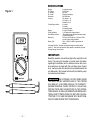
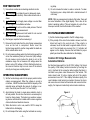
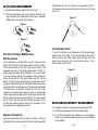
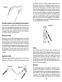
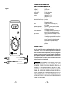
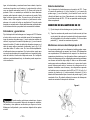
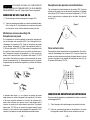
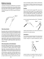
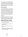
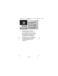
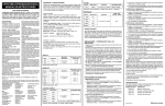
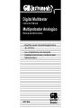
Digital Multitester
Instruction Manual
Multiprobador Analogico
Manual de instrucciones
• Read this owners manual thoroughly before
use and save.
• Lea completamente este manual del
propietario antes del uso y consérvelo para
referencia futura.
GDT-185A
Gardner
Bender
SPECIFICATIONS
Ranges:
DC Voltage:
AC Voltage:
DC Current:
Resistance:
Accuracy:
Figure 1
POWER ON / OFF
DCV
20V
DCA
200mA
200V
Ω
2000Ω
2000
KΩ
ACV
500V
®
GDT-185A
–1–
6 measuring ranges
20-200 Volts
500 Volts
200mA (milliamperes)
200-2000 ohms
DC voltage +/- 1%
AC voltage +/- 2%
Resistance +/-2%
Function/Range switch:
4 functions
6 positions
6 measuring ranges
Display:
3.5 digit LCD readout
Polarity Indication:
'(-) 'is displayed for negative polarity
Weak Battery Indicator:
“B” is displayed when sufficient operating voltage
of batteries is depleted.
Battery Life:
100 hours (LR-44 type bat.), 160 hours (SR-44
type bat.) under normal conditions.
Battery Type:
Uses -2- #LR-44 or #SR-44 type button cell
batteries
Overrange Indication: The three least significant digits are zeroed and the
number “1 “ blinks at the left when the range capacity is exceeded by the input.
Storage/Carrying Case Included
IMPORTANT:
Read this operators manual thoroughly before using this multitester. This manual is intended to provide basic information
regarding this multitester and to describe common test procedures which can be made with this unit. Many types of appliance, machinery and other electrical circuit measurements are
not addressed in this manual and should be handled by experienced service technicians.
! WARNING USE EXTREME CAUTION WHEN USING
THIS MULTITESTER. IMPROPER USE OF THIS TESTER
CAN RESULT IN SEVERE DAMAGE TO PROPERTY,
SEVERE PERSONAL INJURY OR DEATH. FOLLOW ALL
INSTRUCTIONS AND SUGGESTIONS IN THIS OPERATORS MANUAL AS WELL AS OBSERVING NORMAL ELECTRICAL SAFETY PRECAUTIONS. DO NOT USE THIS MULTITESTER IF YOU ARE UNFAMILIAR WITH ELECTRICAL
CIRCUITS AND PROPER TEST PROCEDURES.
– 2–
FOR YOUR SAFETY
ing strap.
1) Use extreme caution when checking electrical circuits.
2)
3)
! WARNING Do not stand in wet or damp work areas
when working with electricity. Wear rubber soled boots or
shoes.
! WARNING Do not apply more voltage or current than
the set range of the multitester will allow.
4)
! WARNING Do not touch the metal probes of the test
leads when making a measurement.
5)
! WARNING Replace worn test leads. Do not use test
leads with broken or tattered insulation.
6) Discharge a capacitor before measuring it.
7) Remove the test leads from the circuit being measured as
soon as the test is completed. Never reset the
function/range switch to another range while the leads are
still in contact with a circuit.
8) Do not measure voltage when the function/range switch is
set on the resistance (ohms) or the current (mA) settings.
Do not measure current when the tester is set on the
resistance range. Do not measure AC voltage when the
tester is set on DC voltage or DCmA. Setting the tester on
the incorrect function may burn out some of the internal
circuitry and may pose a safety hazard.
OPERATING SUGGESTIONS
1) Set the function/range switch to the proper position before
making a measurement. When the voltage or current is
not known, it MUST be determined that the capacity of the
selected range will handle the amount of voltage or current in the circuit (see #3 under “For Your Safety”).
2) Avoid placing the tester in areas where vibration, dust or
dirt are present. Do not store the tester in excessively hot,
humid or damp places. This tester is a sensitive measuring device and should be treated with the same regard as
other electrical and electronic devices.
5) Do not immerse the tester in water or solvents. To clean
the housing use a damp cloth with a minimal amount of
mild soap.
NOTE: With any measurement made by this tester, there will
be some fluctuation of the digital display. This is due to the
testers’ sampling method. This unit samples at a rate of two
times per second, thus the fluctuation of the readout.
DC VOLTAGE MEASUREMENT
1) Set the function/range switch to the DC voltage range.
2) If the polarity of the circuit to be tested is known, touch the
black test lead to the neutral side. If the polarity is
unknown, touch the test leads to opposite sides of the circuit. If the test leads are reversed, the “(-)” indicator will
appear on the display. Reverse the test leads for proper
polarity and read the value indicated on the display.
Common DC Voltage Measurements
Automotive Batteries
Set function/range switch to the 20 DCV setting. First check
the quality of the battery terminal connector by touching the
red (+) test lead to the connector while touching the black (-)
test lead to any bare metal framework of the vehicle. The
tester should read 12 volts or higher with all of the vehicle
accessories turned off. If the display fluctuates rapidly, this
could indicate a bad terminal connection. Remove the terminal connectors and clean both terminals and connectors thoroughly. For improved conductivity and corrosIon resistance,
Figure 2
3) When the tester is not in use, switch it OFF to keep the
batteries from discharging.
4) Do not transport the tester using the test leads as a carry-
–3–
–4–
coat the terminals and connectors with GB #OX-100 anti-oxidant compound (available at your local hardware store).
Replace and tighten the terminal connectors. Secondly, if the
terminals and connectors are making good contact, touch the
test leads to the battery and vehicle framework as described
above (see fig. 2). Note the reading of the tester. Get an
assistant to turn on the headlights while the test leads are
making contact. The reading should drop a few volts. Should
the reading drop 5 volts or more, the battery should be
charged or possibly replaced if the voltage drop is significant.
The circuit may need to be checked further for problems within the electrical system that may be draining the battery.
Figure 3
Alternators and Generators
Set the function/range switch to the DCV range. While the
engine is idling at normal operating speed, touch the black (-)
test lead to the metal framework of the vehicle, then touch the
red (+) test lead to the output terminal connector. The alternator output cable is always the heaviest gauge cable
attached to the alternator (see fig. 3). The display should read
12 volts or more. If the display fluctuates rapidly, the cable
may need to be tightened. If the engine is idling lower than is
specified in the vehicle owners manual, the voltage reading
will be lower. If the output voltage is significantly low, the alternator may require service or replacement.
! WARNING When making automotive measurements,
observe safety precautions. Stay away from the fan blades,
belts and other moving parts of the engine. Keep the multitester and its leads away from moving parts.
Household Batteries
red (+) lead to the (+) terminal of the battery and the black (-)
lead to the (-) terminal of the battery. Read the voltage level of
the battery on the display. Generally speaking, if a battery’s
output voltage falls below 60% - 70% of its original rating, it
should be replaced.
DC MILLIAMP MEASUREMENT
1) Set the function/range switch to the mA setting.
2) Touch the test leads to the circuit in series (in line with the
circuit) so that the circuit current passes through the multitester in order to make the measurement. If the display
reads “(-)” polarity, reverse the test leads.
Common DC Milliamperage Measurements
It is important to point out that milliamps can also be
expressed as thousandths of an Ampere. Therefore 200 milliamps is 200 thousandths of one Amp. The milliamperage
function of your multitester is commonly used by electronics
repair technicians and hobbyists to troubleshoot various low
voltage circuits. Although not normally used for electrical troubleshooting around the home, this function can be used to
measure the milliamperage draw of household items such as
flashlights, and similar low voltage consuming items that do
not draw more than 200mADC. In figure 4 the red (+) test lead
is hooked up to the (+) terminal of the lantern battery while the
black (-) test lead is hooked up to the bulb. The tester will indicate the milliamperage draw when the flashlight switch is
thrown in the ON position.
Figure 4
! WARNING DO NOT APPLY VOLTAGE TO THE TEST
LEADS WHILE THE TESTER IS SET IN THE MILLIAMP
RANGE. See #8 under "For Your Safety".
Set the function/range switch to the DCV setting. Touch the
–5–
–6–
AC VOLTAGE MEASUREMENT
1) Set the function/range switch to the ACV range.
2) Touch the test leads to the circuit under test. With AC voltage, the polarity of the test leads is not a factor. Read the
voltage level of the circuit on the display.
VAC between the two “hot” sides of the receptacle, and 110
VAC between the neutral slot and either of the two “hot” sides
(see fig. 7).
Figure 7
Figure 5
Figure 6
Circuit Breaker Panel
Common AC Voltage Measurements
Wall Receptacles
If the receptacle is controlled by a switch, make sure the
switch is ON. Set the function/range switch to the ACV setting.
Touch the test leads to the “hot” and “neutral” slots of the
receptacle (see fig. 5). The display should read 110 VAC. To
test for proper grounding of the receptacle, touch one test lead
to the ‘hot” (narrow) side of the receptacle, and the other test
lead to the ground slot. The tester should read 110 VAC as
before. To test for proper grounding of non-polarized receptacles (fig.6), alternately touch the test leads between the receptacle slots and the wall plate screw. The tester should indicate
110 VAC when one test lead contacts the “hot” side of the
receptacle. If ground contact cannot be made on the wall plate
screw, remove the wall plate and touch the electrical box with
the test lead in the same manner as before. The tester should
read 110 VAC with one test lead touching the electrical box
and the other touching the live side of the receptacle. If not,
the receptacle is not properly grounded.
To test for defective circuit breakers, set the function/range
switch to the ACV setting. Touch one test lead to the neutral
(buss) terminal strip of the breaker panel and the other test
lead to the terminal on the circuit breaker (see fig. 8). The
tester should read 110 VAC.
Figure 8
RESISTANCE/CONTINUITY MEASUREMENT
For resistance and circuit continuity testing with power OFF
1) Set the function/range switch to the ohms setting.
Appliance Receptacles
Set the function/range switch to the ACV setting. Touch the
test leads to the receptacle slots. The tester should read 220
2) Touch the test leads to the resistance or non-energized
circuit to be measured. Measure the value of the reading
on the display.
–7–
–8–
prong ends of the cord. The tester should indicate a low resistance value. lf not, flex the cord while the leads are still in contact with the metal prongs. If the display changes erratically
when the leads are applied, there may be a broken conductor
in the cord. If the display does not change at all there may be
an open circuit in the appliance. Should it be determined that
the cord is not the source of the problem, the appliance may
need to be disassembled in order to pinpoint the problem.
Refer to the owners manual of the appliance. The manufacturer of the appliance may require that the appliance be serviced
only by a qualified repair technician.
Figure 9
Common resistance and continuity measurements
Figure 12
Continuity tests are probably the most frequently performed
electrical troubleshooting procedures around the home.
Always remember that continuity checks are to be made with
the power to the circuit turned OFF. Polarity of the test leads is
not a factor in making continuity checks.
Extension Cords
Unplug the cord. Set the function/range switch to one of the
ohms settings. Touch one of the test leads to one of the metal
prong ends of the cord and insert the other lead in either one
of the receptacle slots on the other end of the cord, making
sure both leads are making good contact (see fig. 9). If a reading does not register, switch one of the test leads to the opposite receptacle or prong, making sure of good contact. If a
reading still does not register, the cord may need to be
replaced.
Appliance Cords
Unplug the appliance from its power source. Turn its power
switch to the ON position. Touch the test leads to the metal
Fuses
Note: With the power OFF, always remove a fuse from its
socket before testing it. With cartridge fuses, touch the test
leads to each end of the fuse (see fig. 10). If the fuse is good,
the display should read -0- ohms. If not, replace the fuse. On
plug-type fuses, touch the test leads on the bottom contact
and the other on the threaded metal contact (see fig. 11). On
time-delay/tamper-proof fuses, the other metal contact is at
the top of the ceramic threads.
Switches
Figure 10
Figure 11
–9–
Cut off the power source to the switch. If necessary, remove
the switch from whatever it’s mounted to. Turn the switch to
the ON position and touch the test leads to the switches terminals (see fig. 12). If the switch is good, the display should read
-0- ohms. If not, replace the switch. On other than two-way
SPST (single pole, single throw) switches such as three-way
– 10 –
light switches or double pole double throw (ON-OFF-ON)
switches, in each ON position you will need to alternate the
test leads between the switches terminals to determine which
two terminals control that ON position.
NOTES
Heating Elements
Household appliances such as coffee makers and water
heaters contain heating elements which may require troubleshooting. When making continuity checks on heating elements, disconnect the element(s) from the circuit(s) that supply it/them. Touch the test leads, one on each end of the element and observe the display. The reading should indicate
low ohms. If the display doesn’t change, the heating element
may be broken. If the element(s) show that continuity exists,
test for continuity of the circuit(s) that feed the element(s).
Thermostats
Make sure the thermostat control is in the OFF position. Remove
the thermostat cover. Touch the test leads to the contact points
on the thermostat. The display should read -0- ohms. If not,
either one of the contacts may be loose or broken.
BATTERY AND FUSE REPLACEMENT
1) Remove the screw in the back cover of the tester and
carefully separate the back cover from the front.
2) Note the polarity of the batteries when removing them
from their compartments and replace.
3) Use GB catalog number GF-0180 0.2A/ 250V replacement fuses.
4) Carefully replace the back cover and tighten the screw. Do
not overtighten the screw as this may strip the threads in
the tester housing.
–11 –
– 12 –
ORDER FORM
Learn more about using multitesters with "How To Use Your
Multitester For Electrical Testing and Troubleshooting". A
160 page guide to using analog and digital multitesters.
Contains nine chapters of easy to understand instructions
on basic household, automotive electrical and electronic circuit testing. Packed with illustrations. Paperback bound.
Available wherever multitesters are sold or:
Send check or money order for $14.23 per copy ($12.23
plus $2.00 per copy shipping and handling) to:
GB Electrical, Inc.
6101 N. Baker Rd.
Milwaukee, WI 53209
PLEASE PRINT CLEARLY
Name__________________________________________________
Address________________________________________________
City______________________State__________Zip_____________
Qty. Ordered________________________
– 13 –
– 14–
ESPECIFICACIONES DEL
MULTIPROBADOR DIGITAL
Márgenes:
Voltaje de CC:
Voltaje de CA:
Corriente de CC:
Resistencia:
Precisión:
Figura 1
POWER ON / OFF
DCV
20V
DCA
200mA
200V
Ω
2000Ω
2000
KΩ
ACV
500V
6 márgenes de medición
20-200 voltios
500 voltios
200 mA (miliamperios)
200-2000 ohmios
Voltaje de CC +/- 1%
Voltaje de CA +/- 2%
Resistencia +/- 2%
Interruptor de función/margen: 4 funciones
6 posiciones
6 márgenes de medición
Visor:
Lectura en visor de cristal líquido (LCD)
de 3.5 dígitos
Indicación de polaridad:
Se presenta "(-)" para la polaridad negativa
Indicador de batería agotada: Se presenta "B" cuando se ha agotado el volta
je suficiente de las baterías.
Duración de la batería:
100 horas (tipo de bat. LR-44). 160 horas (tipo
de bat. SR-44) bajo condiciones normales.
Tipo de batería:
Utiliza -2- baterías estilo botón tipo Nº LR-44 ó
Nº SR-44
Indicación de margen excedido: Los tres dígitos
menos significativos quedan en cero y el
número "1" pestañea a la izquierda cuando la
entrada supera la capacidad de margen.
Incluye estuche para guardar o llevar el
probador.
IMPORTANTE:
®
GDT-185A
Lea este manual del operador completamente antes de utilizar este
multiprobador. El fin de este manual es proporcionar información
básica relacionada con este multiprobador y describir procedimientos
comunes de prueba que pueden realizarse con esta unidad. Muchos
tipos de aparatos, maquinaria y otras mediciones de circuitos eléctricos
no se mencionan en este manual y debe solicitarse la asesoría de
técnicos de servicio experimentados.
! PRECAUCION SEA SUMAMENTE PRECAVIDO CUANDO USE
ESTE MULTIPROBADOR. EL USO INDEBIDO DE ESTE
PROBADOR PUEDE PROVOCAR GRAVES DAÑOS A LA
PROPIEDAD, Y LESIONES PERSONALES GRAVES O FATALES.
SIGA TODAS LAS INSTRUCCIONES Y SUGERENCIAS DE ESTE
MANUAL DEL OPERADOR Y OBSERVE ADEMAS LAS PRECAUCIONES NORMALES DE SEGURIDAD ELECTRICA. NO UTILICE
ESTE MULTIPROBADOR SI NO TIENE EXPERIENCIA EN CIRCUITOS ELECTRICOS Y DESCONOCE LOS PROCEDIMIENTOS
CORRECTOS DE PRUEBA.
– 15 –
– 16 –
PARA SU SEGURIDAD
1)
Sea sumamente precavido cuando revise circuitos eléctricos.
2)
! PRECAUCION Aléjese de las áreas mojadas o húmedas cuan
do trabaje con electricidad. Use botas o zapatos con suelas de goma.
3)
! PRECAUCION No aplique más voltaje o corriente que lo permitido
por el margen fijado en el multiprobador.
4)
! PRECAUCION No toque las sondas metálicas de los conectores
de prueba cuando realice mediciones.
5)
Reemplace los conectores de prueba desgastados.
No use conectores de prueba con aislamientos rotos o agrietados.
! PRECAUCION
6)
Descargue un condensador antes de medirlo.
7)
Retire los conectores de prueba del circuito que se mida tan
pronto concluya la prueba. Nunca restablezca el interruptor de
función/margen en otro margen mientras los conectores estén
todavía en contacto con un circuito.
8)
No mida el voltaje cuando el interruptor de función/margen esté
fijo en las posiciones de resistencia (ohmios) o los de corriente
(mA). Nunca mida la corriente cuando el probador esté fijo en el
margen de resistencia. Nunca mida el voltaje de CA cuando el
probador esté fijo en el voltaje de CC o CCmA. Si establece el
probador en la función incorrecta puede fundir algunos de los
circuitos internos y presentar riesgos de seguridad.
SUGERENCIAS DE OPERACION
1)
Fije el interruptor de función/margen en la posición correcta antes
de efectuar una medición. Cuando se desconozca el voltaje o la
corriente, DEBE determinarse que la capacidad del margen
seleccionado acepte la cantidad de voltaje o corriente del circuito
(vea el No. 3 bajo el título "Para su seguridad".
2)
Evite colocar el probador en áreas donde exista vibración, polvo
o suciedad. No almacene el probador en lugares excesivamente
calientes, mojados o húmedos. Este probador es un dispositivo
de medición sensible y debe ser tratado con la misma consideración
que otros dispositivos eléctricos y electrónicos.
3)
Cuando el probador no esté en uso, colóquelo en la posición
apagada (OFF) para evitar que se descarguen las baterías.
4)
No traslade el probador utilizando los conectores de prueba
como tira de transporte.
– 17 –
5)
Nunca sumerja el probador en agua ni solventes. Para limpiar la
caja utilice un paño húmedo con una cantidad mínima de jabón
suave.
NOTA: Con cualquier medición efectuada por este probador, habrá
cierta fluctuación del visor digital. Esto se debe al método de prueba
del probador. Esta unidad prueba a razón de dos veces por segundo,
por ende se detecta la fluctuación en la lectura.
MEDICION DEL VOLTAJE DE CC
1)
Fije el interruptor de función/margen en el margen de voltaje de CC.
2)
Si se conoce la polaridad del circuito a ser probado, toque el
conector de prueba negro con el lado neutro. Si la polaridad se
desconoce, toque los conectores de prueba en los lados opuestos
del circuito. Si se invierten los conectores de prueba, aparecerá
en el visor el indicador "(-)". Invierta los conectores de prueba
según la polaridad correcta y lea el valor indicado en el visor.
Mediciones comunes de voltaje de CC
Baterías automotrices
Fije el interruptor de función/margen en 20 VCC. En primer lugar
revise la calidad del conector del terminal de la batería tocando el
conector de prueba rojo (+) con el conector mientras toca el conector de prueba negro (-) con cualquier estructura metálica al descubierto del vehículo. El probador debe indicar 12 voltios o más con
todos los accesorios del vehículo apagados. Si el visor fluctúa rápidamente, esto podría indicar que hay un desperfecto en la conexión
del terminal. Retire los conectores del terminal y limpie ambos terminales y conectores completamente. Para una mejor conectividad y
Figura 2
resistencia a la corrosión,aplique a los terminales una película de
compuesto antioxidante GB No. OX-100 (disponible en su ferretería
local). Reemplace y apriete los conectores del terminal. En segundo
– 18 –
lugar, si los terminales y conectores hacen buen contacto, toque los
conectores de prueba con la batería y la estructura del vehículo
como se describe más arriba (vea la fig. 2). Observe la lectura del
probador. Pida a un asistente que encienda las luces delanteras
mientras están haciendo contacto los conectores de prueba. Debe
bajar la lectura algunos voltios. En caso de que la lectura baje 5
voltios o más, debe cargarse la batería o posiblemente reemplazarse si la caída del voltaje es significativa. El circuito puede
necesitar ser revisado más a fondo para determinar problemas dentro del sistema eléctrico que pueden estar consumiendo la batería.
Baterías domésticas
Fije el interruptor de función/margen en la posición de VCC. Toque
el conector de prueba rojo (+) con el terminal (+) y el conector de
prueba negro (-) con el terminal (-) de la batería. Lea el nivel del
voltaje de la batería en el visor. Generalmente, si el voltaje de salida
de una batería baja del 60% - 70% de su capacidad nominal original,
debe reemplazarse.
MEDICION DE MILIAMPERIOS DE CC
1)
Fije el interuptor de función/margen en el position de mA.
2)
Toque los conectores de prueba con el circuito en serie (en línea
con el circuito) de modo que la corriente del circuito pase a través
del multiprobador a fin de realizar la medición. Si el visor indica
polaridad "(-)", invierta los conectores de prueba.
Alternadores y generadores
Fije el interruptor de función/margen en el margen de VCC. Mientras
el motor está en neutro a una velocidad normal de funcionamiento,
toque el conector de prueba negro (-) con la estructura metálica del
vehículo, luego toque el conector de prueba rojo (+) con el conector
terminal de salida. El cable de salida del alternador siempre es el
cable de mayor calibre conectado al alternador (vea la fig. 3). El
visor debe indicar 12 voltios o más. Si el visor fluctúa rápidamente,
el cable puede tener que apretarse. Si el motor está en neutro pero
con menos revoluciones que lo especificado en el manual del propietario del vehículo, la lectura de voltaje será menor. Si el voltaje de
salida es considerablemente bajo, el alternador puede requerir servicio o sustitución.
Figura 3
Mediciones comunes de miliamperaje de CC
Es importante señalar que los miliamperios también pueden expresarse como milésimas de un amperio; por lo tanto, 200 miliamperios
son equivalentes a 200 milésimas de un amperio. Los técnicos en
reparaciones electrónicas y los aficionados utilizan comúnmente la
función de miliamperage de su multiprobador para resolver problemas
con diversos circuitos de bajo voltaje. Si bien no se utiliza normalmente para resolver problemas eléctricos en la casa, esta función
puede utilizarse para medir el consumo de miliamperios de los
aparatos domésticos como linternas y otros dispositivos operados
con baterías que no consumen más de 200 mA CC. En la fig. 4 el
conector de prueba rojo (+) está conectado al terminal (+) de la
batería de linterna mientras que el conector de prueba negro (-) está
conectado al foco. El probador indicará el consumo de miliamperios
cuando se encienda el interruptor de la linterna.
Figura 4
! PRECAUCION Cuando realice mediciones automotrices, observe
las precauciones de seguridad. Aléjese de las aspas de ventilador,
las bandas y otras piezas en movimiento que haya en el motor.
Mantenga el multiprobador y sus conectores alejados de las partes
móviles.
– 19 –
– 20 –
! PRECAUCION NO APLIQUE VOLTAJE A LOS CONECTORES DE
PRUEBA MIENTRAS EL PROBADOR ESTE FIJO EN EL MARGEN
DE MILIAMPERIOS. Vea el Nº. 8 bajo el titulo "Para su seguridad".
MEDICION DE VOLTAJE DE CA
1)
Fije el interruptor de función/margen en el margen VCA.
2)
Toque los conectores de prueba con el circuito sometido a prueba.
Con el voltaje de CA, la polaridad de los conectores de prueba
no es un factor. Lea el nivel de voltaje del circuito en el visor.
Receptáculos de aparatos electrodomésticos
Fije el interruptor de función/margen en la posición VCA. Toque los
conectores de prueba con las ranuras del receptáculo. El probador
debe indicar 220 VCA entre los dos lados "energizados" y 110 VCA
entre la ranura neutra y cualquiera de los dos lados "energizados"
(vea la fig. 7).
Figura 7
Mediciones comunes de voltaje CA
Receptáculos de pared
Si el receptáculo se controla mediante un interruptor, asegúrese de
que el interruptor esté encendido (ON). Fije el interruptor de función/margen en la posición VCA. Toque los conectores de prueba
con las ranuras "energizada" y "neutra" del receptáculo (vea la fig.
5). El visor debe indicar 110 VCA. Para probar si el receptáculo tiene
la conexión a tierra correcta, toque un conector de prueba con el
lado "energizado" (angosto) del receptáculo, y el otro conector de
prueba con la ranura a tierra. El probador debe indicar 110 VCA
como antes. Para probar la conexión a tierra correcta de los receptáculos no polarizados (fig. 6), alternadamente toque los conectores
de prueba entre las ranuras del receptáculo y el tornillo de la lámina
de la pared.
Panel cortacircuitos
Para probar si existen desperfectos en los cortacircuitos, fije el interruptor de función/margen en la posición VCA. Toque un conector de
prueba con la tira terminal neutra (buss) del panel disyuntor y el otro
conector de prueba con el terminal del cortacircuitos (vea la fig. 8).
El probador debe indicar 110 VCA.
Figura 8
Figura 5
Figura 6
El probador debe indicar 110 VCA cuando un conector de prueba
haga contacto con el lado "energizado" del receptáculo. Si el contacto de tierra no puede realizarse en el tornillo de la lámina de la
pared, retire la lámina de la pared y toque la caja eléctrica con el
conector de prueba de la misma manera que antes. El probador
debe indicar 110 VCA con un conector de prueba tocando la caja
eléctrica y el otro tocando el lado energizado del receptáculo. De lo
contrario, el receptáculo no está debidamente conectado a tierra.
– 21 –
MEDICION DE RESISTENCIA/CONTINUIDAD
Para la prueba de resistencia y continuidad de circuitos con la electricidad apagada (OFF).
1)
Fije el interruptor de función/margen en la posición de ohmios.
2)
Toque los conectores de prueba con la resistencia o el circuito
no energizado a medir. Mida el valor de la lectura en el visor.
– 22 –
Mediciones comunes de
resistencia y continuidad
Las pruebas de continuidad son probablemente las que se efectúan
más a menudo en procedimientos para resolver problemas eléctricos
en la casa. Siempre recuerde que las revisiones de continuidad
deben realizarse con el circuito apagado (OFF). La polaridad de los
conectores de prueba no es un factor al realizar revisiones de
continuidad
Figura 9
marse a fin de identificar el problema. Consulte el manual del propietario del aparato. El fabricante del aparato puede requerir que el
aparato reciba servicio solamente de un técnico de reparación
capacitado.
Fusibles
Nota: Con el suministro eléctrico apagado (OFF), siempre retire un
fusible del zócalo antes de probarlo. Con los fusibles de cartucho,
toque los conectores de prueba con cada extremo del fusible (vea la
fig. 10). Si el fusible está en buen estado, el visor debe indicar -0ohmios. De lo contrario, reemplace el fusible. En fusibles de tipo
enchufe, toque los conectores de prueba con el contacto inferior y el
otro con el contacto de metal roscado (vea la fig. 11). En fusibles de
Figura 10
Figura 11
Cables de extensión
Desenchufe el cable. Fije el interruptor de función/margen en una de
las posiciones de ohmios. Toque uno de los conectores de prueba
con uno de los extremos de las espigas de metal del cable, e inserte
el otro conector de prueba en cualquiera de las ranuras receptoras
en el otro extremo del cable, asegurándose de que ambos conectores estén haciendo buen contacto (vea la fig. 9). Si no se registra
ninguna medición, cambie uno de los conectores de prueba al receptáculo o espiga opuesto, asegurando nuevamente que haya buen
contacto. Si todavía no obtiene ninguna lectura, puede tener que
reemplazar el cable.
retardo/a prueba de alteraciones, el otro contacto de metal está en la
parte superior de los roscados cerámicos.
Interruptores
Corte el suministro de energía al interruptor. Si es necesario, retire el
interruptor de cualquiera sea el dispositivo al que esté montado.
Coloque el interruptor en la posición encendida (ON) y toque los
Figura 12
Cables de aparatos electrodomésticos
Desenchufe el aparato de la toma de energía. Coloque su interruptor
en la posición de encendido (ON). Toque los conectores de prueba
con los extremos de las espigas de metal del cable. El probador
debe indicar un bajo valor de resistencia. De lo contrario, doble el
cable mientras los conectores todavía se hallen en contacto con las
espigas metálicas. Si el visor cambia irregularmente cuando se aplican los conectores, puede haber un conductor defectuoso en el
cable. Si el visor no cambia en absoluto puede haber un circuito
abierto en el aparato. En caso de determinarse que el cable no es lo
que origina el problema, entonces el aparato puede tener que desar-
conectores de prueba con los terminales del interruptor (vea la fig. 12).
Si el interruptor está en buen estado, el visor debe indicar -0-
– 23 –
– 24 –
ohmios. De lo contrario, reemplace el interruptor. En interruptores
que no sean SPST (unipolar, de una vía) bidireccionales como los
interruptores de luz de tres tiempos o los interruptores bipolares de
doble vía (ON-OFF-ON), en cada posición de encendido (ON)
deberá alternar los conectores de prueba entre los terminales de
interruptores para determinar cuál de los dos terminales controla
dicha posición encendida (ON).
Elementos calentadores
Los aparatos electrodomésticos tales como cafeteras y wafleras
contienen elementos calentadores que pueden necesitar reparaciones. Cuando realice revisiones de continuidad en elementos
calentadores, desconecte el(los) elemento(s) del(los) circuito(s) que
los alimentan. Toque los conectores de prueba, uno en cada
extremo del elemento y observe. La lectura debe indicar pocos
ohmios. Si el visor no cambia, está roto el elemento calentador. Si
el(los) elemento(s) demuestran que existe continuidad, pruebe la
continuidad del(los) circuito(s) que alimentan el(los) elemento(s).
Termostatos
Asegúrese de que el control de termostato esté en la posición apagada
(OFF). Retire la tapa del termostato. Toque los conectores de prueba
con los puntos de contacto en el termostato. El visor debe indicar -0ohmios. De lo contrario, alguno de ellos puede estar suelto o roto.
REEMPLAZO DE BATERIAS Y FUSIBLES
1)
Retire el tornillo en la tapa posterior del probador y cuidadosamente
separe la tapa posterior de la delantera.
2)
Observe la polaridad de la batería cuando la retire de su compartimiento y reemplácela.
3)
Use fusibles de repuesto de 0.2A/125V con el número de catálogo
GB GF-0180.
4)
Cuidadosamente reemplace la tapa posterior y apriete el tornillo.
No apriete en exceso el tornillo porque esto puede dañar los
roscados de la estructura del probador.
NOTAS.
– 25 –
– 26–
FORMULARIO DE PEDIDO
Conozca más sobre el uso de los multiprobadores con "How to Use
Your Multitester for Electrical Testing and Troubleshooting" (Cómo
usar su multiprobador para pruebas y resolución eléctricas), una
guía de 160 páginas para utilizar multiprobadores analógicos y
digitales. Contiene nueve capítulos de instrucciones fáciles de entender
acerca de las pruebas de circuitos eléctricos y electrónicos en
aplicaciones caseras y automotrices. Incluye numerosas ilustraciones.
Encuadernación económica. Disponible en todas las tiendas donde
se vendan multiprobadores o:
Envíe un cheque u orden de pago por US$14.23 por ejemplar
(US$12.23 más US$2.00 por ejemplar con gastos de envío) a:
GB Electrical, Inc.
6101 N. Baker Rd.
Milwaukee, Wisconsin 53209 EE.UU.
SIRVASE ESCRIBIR CON CLARIDAD
Nombre
Dirección
Ciudad
Estado
Código postal
Cant. pedida
– 27 –
– 28–
Gardner
Bender
www.gardnerbender.com
PO Box 3241 • Milwaukee, WI 53201-3241 • 414-352-4160
6615 Ordan Drive • Mississauga, Ontario L5T 1X2 • 905-564-5749
ZX000135 Rev. A