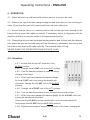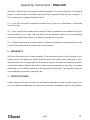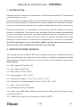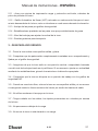
1
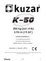
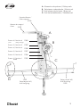
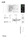
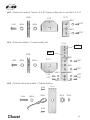
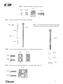
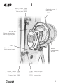
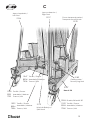
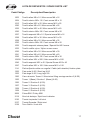
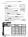
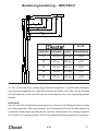
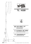
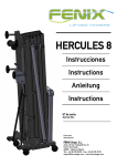
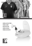
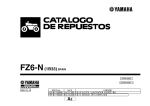
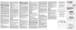
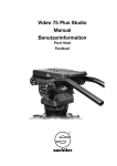
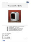
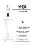
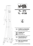
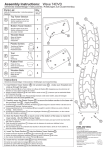
English - User Manual
Español - Manual de Usuario
Deutch - Bedienungsanleitung
KUZAR SYSTEMS S.L.
Version.15/09
300 kg (661.4 lb)
5.95 m (19.52’)
KUZAR SYSTEMS S.L.
C/ Ciudad de Ferrol Nº8
Pol.Ind. Fuente del Jarro
46988 Paterna - Valencia (Spain)
Made in Spain (EU)
Manual de usuario propiedad de KUZAR SYSTEMS S.L. Deposito legal y copyright 2014.
Todos los derechos reservados.
K-50
2
A - Reenvios de poleas / Pulleys sets
B - Set piezas cabrestante / Winch set
C - Set piezas de la base / Base set
D - Set del estabilizador / Stabilizer set
Soporte Brazos /
Forks support
2196
Brazos de carga /
Forks
2159
A
Tramo 6 / Section 6
1360
Tramo 5 / Section 5
1359
Tramo 4 / Section 4
1358
Tramo 3 / Section 3
1357
Tramo 2 / Section 2
1356
Tramo 1 / Section 1
Base
1355
Carro
D
Lifting carriage
1223
Pata larga K-40 /
K-40 Long leg
B
C
Pata corta K-40 /
K-40 Short leg
1222
3
Tornillo /
Screw
1029
Arandela /
Washer
8001
Gatillo KAT /
KAT Lock
Taco Gatillo/
Lock rest
2138
2185
2156
2157
4
A
Vista en Planta superior /
Top view
A.4
A.5
A.2
A.2
A.2
A.2
A.1
A.1 - Reenvío superior Tramo 1 Base / Upper pulley set on Section 1 Base
2166
2008
1032
8004
8004
2167
8001 1027
5
A.2 - Reenvío superior Tramos 2 a 5/ Upper pulley set on sections 2 to 5
2008
2179
2175
8001
1032
8004
1027
8004
8001
1027
A.3 - Reenvío inferior / Lower pulley set
8004
A.9
A.8
2008
1032
2174
8001
2175
8004
1027
8001
1027
8001
1027
1027
1027
1027
A.4 - Fijación final de cable / Cable fixation
1026
1046
8004
9050
8001
8001
8001
1114
8013
7006
1026
6
A.5 - Rodillo Nylon / Nylon roller
2177
7002
8003
1033
A.6 - Freno de Inercia / Inertial break
1026
2146
A.7 - Tornillo fijación soporte brazos /
Fixation screw for the forks support
2144
1004
1043N
2145
A.8 - Taco tope barras superior / Upper stop piece
2143
2142
8009
1030
8009
1030
7007
A.9 - Taco tope barras inferior / Lower stop piece
2176
1042
1042
7
B
Tornillo / Screw 1028
Arandela / Washer 8003
Tuerca / Nut 7002
Cable de acero /
Steel cable
9050
2173N
Placa cabrestante /
Winch support plate
2193
Placa tirantes /
Strut support plate
Tornillo / Screw 1036
Arandela / Washer 8006
Tuerca / Nut 7001
4004
Cabrestante /
Winch
1036 Tornillo / Screw
8001 Arandela / Washer
7001 Tuerca / Nut
8
C
Apoyo derecho /
Right strut
Apoyo izquierdo /
Left strut
2137
2136
Pomo transporte patas /
Transport security knob
2190
1047 Tornillo / Screw
8004 Arandela / Washer
7006 Tuerca / Nut
2189
Gatillo patas /
Security leg lock
2187
Base K-50
1020 Tornillo / Screw
8001 Arandela / Washer
7001 Tuerca / Nut
1022 Tornillo / Screw
8004 Arandela / Washer
7006 Tuerca / Nut
2119
Nivel de Burbuja /
Spirit level
5004
1022
8004
7006
Rueda /Wheel K-50
Tornillo / Screw
Arandela / Washer
Tuerca / Nut
9
D
Estabilizador completo /
Complete stabilizer kit
2168
2169
7010
7009
1041
2170
1015
8009
2171
2172
8006
1003
10
LISTA DE REPUESTOS / SPARE PARTS LIST
Code/Código
Description/Descripción
1003
Tornillo allen M8 x 16 / Allen screw M8 x 16
1004
Tornillo cónico M5 x 12 / Conic screw M5 x 12
1015
Tornillo allen M12 x 25 / Allen screw M12 x 25
1020
Tornillo allen M8 x 25 / Allen screw M8 x 25
1022
Tornillo allen M12 x 40 / Allen screw M12 x 40
1026
Tornillo cónico M8 x 20 / Conic screw M8 x 20
1027
Tornillo especial M8 x 16 / Special screw M8 x 16
1028
Tornillo allen M10 x 30 / Allen screw M10 x 30
1029
Tornillo allen M8 x 35 / Allen screw M8 x 35
1030
Tornillo cónico M8 x 25 / Conic screw M8 x 25
1032
Tornillo especial cabeza plana / Special flat M12 screw
1033
Tornillo rodillo nylon / Nylon runner screw
1036
Tornillo allen M8 x 30 / Allen screw M8 x 30
1041
Tornillo allen M6 x 40 / Allen screw M6 x 40
1042
Tornillo cónico M8 x 30 / Conic screw M8 x 30
1043N Tornillo allen M14 x 200 / Allen screw M14 x 200
1046
Tornillo especial M12 x 45 / Special Screw M12 x 45
1047
Tornillo allen M12 x 100 / Allen screw M12 x 100
1114
Pletina fijación cable con argolla / Cable (with shackle) fixation plate
1222
Pata corta K-50 / Short leg K-50
1223
Pata larga K-50 / Long leg K-50
1360
Carro aluminio Tramo 6 / Aluminium lifting carriage section 6 (K-50)
1355
Tramo 1 (Base) / Section 1 (Base) (K-50)
1356
Tramo 2 / Section 2 (K-50)
1357
Tramo 3 / Section 3 (K-50)
1358
Tramo 4 / Section 4 (K-50)
1359
Tramo 5 / Section 5 (K-50)
2008
Polea Ø90 / Pulley Ø90
2119
Nivel de burbuja / Spirit level indicator
2136
Tirante Izquierda / Left strut
2137
Tirante Derecha / Right strut
2138
Taco Gatillo / Lock rest
11
LISTA DE REPUESTOS / SPARE PARTS LIST
Code/Código
Description/Descripción
2142
Tope tramos / Section Top
2143
Tope roscado tramos / Section screw top
2144
Rampa freno / Brake ramp
2145
Muelle / Spring
2146
Freno de carro / Carriage break
2156
Pasador / Pin
2157
Clip “R” / “R” Shape clip
2159
Brazo de carga / Lifting fork
2166
Cubre cable polea entrada cable / Cable entry pulley cover
2167
Macizo porta-poleas entrada cable / Cable entry support piece
2168
Estabilizador completo / Complete stabilizer
2169
Bola grande de estabilizador / Big stabilizer ball
2170
Manivela grande estabilizador / Big stabilizer handle
2171
Plato grande estabilizador / Big stabilizer plate
2172
Esparrago estabilizador M24 x 400 / Threaded bolt M24 x 400
2173N Placa porta-cabrestante K-50 / Winch plate K-50
2174
Macizo porta-poleas inferior / Lower pulley support piece
2175
Cubre cable polea Ø90 / Pulley cover Ø90
2176
Taco tope tramos ancho / Large stop piece
2177
Rodillo nylon grande / Large nylon roller
2179
Macizo porta-poleas superior / Upper pulley support piece
2185
Gatillo KAT (v.14) / KAT Lock (v.14)
2187
Base Kuzar Mediana (v.14) / Medium Kuzar Base (v.14)
2189
Gatillo patas / Security leg lock
2190
Pomo apriete transporte patas / Transport security knob for legs
2193
Placa sujección tirantes (v.14) / Strut support plate (v.14)
2196
Soporte brazo carga / Fork support
4004
Cabrestante 900kg Manivela larga / 900kg Winch Long handle
5004
Rueda Ø100 (blanca) / Wheel Ø100 (white)
7001
Tuerca M8 autoblocante / Auto-block nut M8
7002
Tuerca M10 autoblocante / Auto-block nut M10
7006
Tuerca M12 autoblocante / Auto-block nut M12
12
LISTA DE REPUESTOS / SPARE PARTS LIST
Code/Código
Description/Descripción
7007
Tuerca mariposa autoblocante / Butterfly nut
7009
Tuerca M12 / Nut M12
7010
Tuerca M6 autoblocante / Auto-block nut M6
8001
Arandela M8 / M8 washer
8003
Arandela M10 / M10 washer
8004
Arandela M12 / M12 washer
8006
Arandela M8 ancha / Wide M8 washer
8009
Arandela M14 / M14 washer
8013
Arandela M12 ancha / Wide M12 washer
9050
Cable K-50 6mm / Cable K-50 6mm
13
Operating Instructions - ENGLISH
1 - INTRODUCTION.
Dear user. Thank you purchasing your Kuzar K-50 lifter. We hope you will be very satisfied with it.
This manual has been written so that you can understand how to effectively use the lift
and most importantly, so that you can use it safely. It is important that you fully read the
manual and follow the instructions carefully before using your lift. All Kuzar lifts undergo
a very strict quality control process during their manufacture.
So that your lift always works properly please only purchase original Kuzar parts from an
authorized distributor or dealer. The user waives all warranty rights if using parts other
than Kuzar or if the product is manipulated in any way by an unauthorized third party.
When requesting parts, please refer to the diagrams of this manual and quote the
serial number and year of manufacture located on your lifter.
2 - TECHNICAL SPECIFICATIONS.
Kuzar lifter, model K-50 has been designed for vertically lifting lighting, trussing etc in the
Professional sound and light sector. For various Kuzar supports available please refer to
our website www.kuzar.es or catalogue.
2.1 - Max. load: 300 kg (661.4 lb)
2.2 - Min. load: 25 kg (55 lb)
2.3 - Max. height: 5.95 m (19.52’)
2.4 - Folded height: 1.57 m (5.15’)
2.5 - Work surface: 1.91 x 2.15 m (6.26’ x 7.05’)
2.6 - Folded base area: 60 cm x 45 cm (1.97’ x 1.48’)
2.7 - Weight: 164 kg (361.56 lb)
2.8 - Winch: 900 kg certified
2.9 - Cable: Steel DIN 3060. Tensile strength 180 kg/mm2. Anti-torsion & anti-corrosion Ø6 mm cable diameter.
2.10 - Construction material: Alluminium profiles 6082T6.
2.11 - Antirust protection priming paint bathed black steel, covered with cured polyester
dust.
K-50
14
Operating Instructions - ENGLISH
2.12 - Kuzar Automatic Trigger (KAT) on each section which automatically slots in to the
sections during elevation, locking them in place.
2.13 - Anchor of the legs by safety catches.
2.14 - Adjustable stabilizer plates in the legs with nonslip rubber base support.
2.15 - Spirit level for vertical alignment.
2.16 - Swivel wheels for transporting the lifter to its working position.
3 - SAFETY GUIDELINE.
3.1 - Situate the tower on a solid and flat surface.
3.2 - Check that the legs are fully inserted and secured in to their housing with the safety
locks.
3.3 - Ensure that the lifter is in a vertical position and use the spirit level located on the
base profile to check. If necessary, adjust its alignment with the plates by turning the
handle in the appropriate direction.
3.4 - Check that the tower is locked in its working position with the safety lock.
3.5 - When used outdoors, place the tower on a hard surface and if necessary secure it
against excess wind force via cable braces.
3.6 - Do not use ladders nor lean them against the lifter.
3.7 - Be careful with any cables, prominent objects etc. placed above the tower.
3.8 - Do not stand underneath the load.
3.9 - Do not move the tower when it is elevated or loaded.
3.10 - Before using the tower, check the condition of the cable. This must be free of cuts
and frays. Never use damaged cables.
3.11 - Never dismount the winch handle or any element of the winch under any circumstance.
3.12 - Once the tower is set-up in its working position we recommended the winch handle is locked to avoid anyone interfering with it.
3.13 - The minimum load for a safe operation of the brake is 25 kg. The brake will not
function without this minimum load.
3.14 - Do not grease or lubricate the brake mechanism of the winch.
3.15 - This lift cannot lift human beings.
3.16 - For transportation it is necessary to retract all profiles and lock them with the
corresponding safety lock.
K-50
15
Operating Instructions - ENGLISH
4 - OPERATION.
4.1 - Place the tower on a flat and solid surface where it is going to be used.
4.2 - Remove the legs from their transport supports and insert them in their working position. Check that they are fully inserted and fixed with their safety lock.
4.3 - Ensure that the lifter is in a vertical position and use the spirit level located on the
base profile to check the bubble is centred. If necessary, adjust its alignment with the
stabilizer plates by turning the handle in the appropriate direction.
4.4 - Change the forks to their horizontal working position and fix them with the fastener
pins, place the load on the forks using a Kuzar Accessory if necessary, and ensure that
the tower is only used to lift loads vertically. The minimum load is 25 kg.
NEVER RAISE THE TOWER SECTIONS WITHOUT LOAD.
4.5 - Elevation:
4.5.1 - Ensure that all the KAT locks are in the
BLOCK position.
4.5.2 - Change the nº1 KAT lock to the LIFT position.
4.5.3 - Turn the handle clockwise to raise the lifting carriage of the tower.
4.5.4 - When you have reached the desired height, fix the nº1 KAT lock in by turning the handle anti-
clockwise. Change the nº1 KAT lock to the BLOCK
1
2 3 4 5
position.
4.5.5 - Change the nº2 KAT lock to the LIFT position.
4.5.6 - Turn the handle clockwise to rise the next section of the tower.
4.5.7 - When you have reached the desired height, fix the nº2 KAT lock in by turning the handle anti-clockwise.
Check that the nº2 KAT lock has introduced in to its corresponding hole.
And change the nº2 KAT lock to the BLOCK position.
4.5.8 - Repeat these steps to raise all the sections of the tower, changing all K-50
16
Operating Instructions - ENGLISH
the KAT locks left orderly to the LIFT position and turning the handle clockwise.
WARNING: The tower can be left in any intermediate height if necessary. Just make
sure that the KAT locks are always fixed and introduced. In the unlikely event of cable
breaking the KAT locks will ensure that the tower stays UP and SECURE.
Your security is our main concern.
IMPORTANT - HOW TO PLACE THE LOAD ON THE LIFTER
Always load as close to the tower as possible.
Follow the instruction of the next picture to place the load correctly, the diagram shows
the load out of the gravity center, with distances to the lifting carriage at a maximum
lifting. Notice that the maximum load diminishes according to the distance from the body
of the tower.
X1
X2
X3
X4
X5
K-50
POSITION
DISTANCE
LOAD
PERCENTAGE
X1
30 cm
300 kg
100%
X2
40 cm
285 kg
95%
X3
50 cm
267 kg
89%
X4
60 cm
210 kg
70%
X5
70 cm
165 kg
55%
K-50
17
Operating Instructions - ENGLISH
4.6 - Descent:
4.6.1 - To fold the tower down, first, turn the handle of the winch clockwise to tighten the steel cable.
4.6.2 - Once the cable is tense, pull out the nº5 KAT lock, mantain it always in
LIFT position but keep it out.
4.6.3 - While you keep the KAT lock out, turn the handle anti-clockwise to bring
down the corresponding section of the tower.
4.6.4 - Once the section has been brought down, release the nº5 KAT lock, and pull out the nº4 KAT lock.
4.6.5 - While you keep the next KAT lock out, turn the handle anti-clockwise to bring down the next section.
4.6.6 - Keep repeating these steps, pulling out all the KAT locks left in order while you turn the handle anti-clockwise.
4.6.7 - Once the tower has been folded down, place all the KAT locks in the BLOCK position.
4.7 - Transport:
Turn the handle of the stabilizers to release tension on the legs in order to pull them out.
Then, place the legs in their transport compartments located at the base of the tower.
Pull out the forks and place them in vertical position. The tower will be ready for transport.
5 - MAINTENANCE.
5.1 - All cables must be checked regularly. Faulty cables must be replaced immediately.
Do not use the lifter with faulty cables as it is potentially very dangerous. Only use DIN
3060 cables, supplied from an authorised dealer.
5.2 - The lifter is delivered ex factory completely greased. Depending on its mechanical
Use though, we recommend that the crown wheel of the winch, the pads & bushings
of the drive shaft, the handle thread and the profiles of the lift are periodically greased.
ATTENTION:
Do not apply oil or grease to the brake mechanism. The brake discs have been pre-grea-
K-50
18
Operating Instructions - ENGLISH
sed with a special heat and pressure resistant grease. To avoid malfunction to the winch
brake, no other products must be used except the original provided by the company. It
is not necessary to grease the brake discs.
5.3 - Your lifter should be inspected at least once a year by a specialized / authorized
service centre.
5.4 - Only original Kuzar spare parts must be used to guarantee the reliability and operational safety of your lifter. The user shall lose all warranty claims if he uses anything
other than original spare parts or modifies this product in any way.
5.5 - In case a spare part is required please indicate the reference number which can be
found in the spare parts list at the back of this manual.
6 - WARRANTY.
All Kuzar lifts come with 2 years warranty. This warranty period is from the date of purchase. Kuzar will repair any defect product caused by either faulty materials or poor
workmanship free of charge within this period as long as the parts are fitted by an authorized Kuzar dealer. Should the product have been manipulated in any way or a repair
attempted by an unauthorized dealer the warranty will be invalid. This warranty does not
cover damage occurred by improper use.
7 - CERTIFICATIONS
Kuzar reserves the right to make any modification/alteration to the lift without prior notice. Any modification/alteration would be an innovation, intended to improve the product.
K-50
19
Manual de instrucciones - ESPAÑOL
1 - INTRODUCCIÓN.
Estimado usuario. Gracias por la compra de su torre elevadora Kuzar K-50. Esperamos
quede satisfecho con ella.
Este manual ha sido escrito para que usted pueda entender cómo utilizar eficazmente
la torre y lo más importante, el modo para que pueda utilizarla con seguridad. Es importante que lea el manual y siga las instrucciones cuidadosamente antes de usar la torre.
Todas las torres Kuzar son sometidas a un proceso de control de calidad muy estricto
durante su fabricación. Para que su torre elevadora funcione siempre correctamente
por favor reemplazar únicamente con piezas originales Kuzar de un distribuidor o concesionario autorizado. El usuario renuncia a todos los derechos de garantía si se usan
piezas que no sean Kuzar o si el producto es manipulado por un tercero no autorizado.
Al solicitar piezas, por favor consulte los dibujos de este manual así como el número de serie y año de fabricación ubicados en el elevador.
2 - ESPECIFICACIONES TÉCNICAS.
Torre elevadora Kuzar, modelo K-50 ha sido diseñada para elevar verticalmente iluminación y las estructuras, etc. para el sector del sonido e iluminación profesional. Existen
diversos soportes disponibles Kuzar, por favor consulte nuestro catálogo o página web:
www.kuzar.es.
2.1 - Max. carga: 300 kg (661.4 lb)
2.2 - Min. carga: 25 kg (55 lb)
2.3 - Max. Altura: 5.95 m (19.52’)
2.4 - Altura plegada: 1.57 m (5.15’)
2.5 - Superficie de trabajo: 1.91 x 2.15 m (6.26‘ x 7.05‘)
2.6 - Superficie de la base plegada: 60 cm x 45 cm (1.97’ x 1.48’)
2.7 - Peso: 164 kg (361.56 lb)
2.8 -Cabrestante: 900 kg certificado.
2.9 - Cable: Acero DIN 3060. Resistencia a la tracción 180 kg/mm2. Anti-torsión y anticorrosión de Ø6 mm.
2.10 - Material de construcción: Perfiles de Aluminio 6082T6.
K-50
20
Manual de instrucciones - ESPAÑOL
2.11 - Acero con pintura de imprimación negra y protección anti-óxido, cubiertos de
polvo de poliéster al horno.
2.12 - Gatillo Automático de Kuzar (KAT) colocado en cada sección bloquea el movimiento descendente de la torre, este se introduce en cada ranura durante la elevación.
2.13 - Anclaje de las patas por gatillos de seguridad.
2.14 - Estabilizadores ajustables en las patas con apoyo antideslizante de goma.
2.15 - Nivel de burbuja para ajustar la vertical de la torre.
2.16 - Ruedas giratorias para transporte.
3 - GUÍA PARA USO SEGURO.
3.1 - Poner la torre sobre una superficie sólida y plana.
3.2 - Comprobar que las patas estén completamente insertadas en su compartimento y
fijadas por el gatillo de seguridad.
3.3 - Asegúrese de que la torre está en una posición vertical, compruébelo haciendo
uso del nivel de burbuja situado en el perfil base. Si es necesario, ajustar su verticalidad
mediante los estabilizadores, girando la manivela en la dirección apropiada.
3.4 - Comprobar que la torre se bloquea en su posición de trabajo con los gatillos de
seguridad KAT.
3.5 - Cuando se usa al aire libre, colocar la torre en una superficie sólida y si es necesario asegurarla contra la fuerza excesiva del viento por medio de tirantes de cable.
3.6 - No utilice escaleras ni las apoye en la torre.
3.7 - Tenga cuidado con los cables, los objetos prominentes etc. situados por encima
de la torre.
3.8 - No permanezca debajo de la carga.
3.9 - No mover la torre si está elevada o con carga.
K-50
21
Manual de instrucciones - ESPAÑOL
3.10 - Antes de utilizar la torre, verificar el estado del cable. Éste debe estar libre de
cortes y desgastes. No utilice nunca cables dañados.
3.11 - Nunca desmontar la palanca del cabrestante o cualquier elemento del cabrestante bajo ninguna circunstancia.
3.12 - Una vez que la torre está puesta a punto en su posición de trabajo es recomendable que la palanca del cabrestante quede bloqueada para evitar cualquier interferencia
con la misma.
3.13 - La carga mínima para un funcionamiento seguro del freno es 25 kg. El freno no
funcionará sin esta carga mínima.
3.14 - No engrasar ni lubricar el mecanismo de freno del cabrestante.
3.15 - Este elevador no puede utilizarse para elevar personas.
3.16 - Para el transporte hay que bajar todos los tramos y bloquearlos con el bloqueo de
seguridad correspondiente.
4 - OPERACIÓN.
4.1 - Coloque la torre en la zona de trabajo, sobre una superficie plana y sólida.
4.2 - Desmonte las patas de sus soportes e insertarlas en su posición de trabajo.
Compruebe que estén completamente insertadas y fijadas con el gatillo de seguridad.
4.3 - Asegurarse de que el elevador está en posición vertical, para ello, servirse del
nivel de burbuja situado en la base, y comprobar que la burbuja está centrada. Si es
necesario, ajuste la verticalidad de la torre con los estabilizadores, girando la manivela
en la dirección apropiada.
4.4 - Coloque los brazos de carga de la torre en posición horizontal de trabajo y fijelos
con los pasadores y clips de seguridad. Coloque un Accesorio Kuzar si se requiere, y
asegurarse de que la torre sólo se utiliza para levantar cargas en sentido vertical.
La carga mínima es de 25 kg. NO ELEVE LA TORRE SIN CARGA.
K-50
22
Manual de instrucciones - ESPAÑOL
4.5 - Elevación:
1
4.5.1 - Asegurese que los gatillos KAT estén en posición de BLOQUEO.
4.5.2 - Cambie el gatillo KAT 1 a posición de
ELEVACIÓN.
4.5.3 - Gire la manivela del cabrestante en sentido horario para elevar el carro.
4.5.4 - Al llegar a la posición deseada, ENCLAVE
el gatillo girando la manivela del cabrestante en
sentido anti-horario. Cambie el gatillo KAT 1 a posi
ción de BLOQUEO y compruebe que se introduce.
4.5.5 - Cambie el gatillo KAT 2 a posición de ELEVACIÓN.
4.5.6 - Gire la manivela del cabrestante en sentido horario para elevar el
siguiente tramo.
4.5.7 - Al llegar a la posición deseada, ENCLAVE el gatillo girando la
manivela del cabrestante en sentido anti-horario. Cambie el gatillo KAT 2
a posición de BLOQUEO y compruebe que se introduce.
4.5.8 - Repita estas operaciones para elevar todos los tramos, cambiando
ordenadamente los gatillos KAT 3, KAT 4 y KAT 5 a posición de ELEVACIÓN
y girando la manivela del cabrestante.
2 3 4 5
X1
X2
X3
K-50
X4
X5
POSICIÓN
DISTANCIA
CARGA
PORCENTAJE
X1
30 cm
300 kg
100%
X2
40 cm
285 kg
95%
X3
50 cm
267 kg
89%
X4
60 cm
210 kg
70%
X5
70 cm
165 kg
55%
K-50
23
Manual de instrucciones - ESPAÑOL
ATENCIÓN: La torre puede dejarse en cualquier posición intermedia si se requiere.
Asegurese siempre de que los gatillos se introduzcan. Ya que en el caso poco probable
de que el cable de acero se rompa los gatillos KAT sujetarían la carga y manterndría la
torre ELEVADA y SEGURA. Su seguridad es nuestra máxima preocupación.
4.6 - Descenso:
4.6.1 - Coloquese frente al cabrestante, y gire la manivela del cabrestante en sentido horario para tensar el cable.
4.6.2 - Con el cable tensado, extraiga el gatillo KAT 5 con su mano izquierda, mantenga el gatillo en posición de ELEVACIÓN pero extraido.
4.6.3 - Mientras mantiene el gatillo extraído, gire la manivela del cabrestante en sentido anti-horario para proceder al descenso de la torre.
4.6.4 - Una vez haya descendido el tramo correspondiente, suelte el gatillo KAT 5, y extraiga esta vez el gatillo KAT 4.
4.6.5 - Con el siguiente gatillo KAT 4 extraido, gire la manivela del cabrestante
en sentido anti-horario para descender el siguiente tramo.
4.6.6 - Repita estos pasos extrayendo los gatillos KAT 1, KAT 2 y KAT 3
mientras gira la manivela en sentido anti-horario.
4.6.7 - Al terminar el descenso de la torre, coloque todos los gatillos KAT en posición de BLOQUEO.
4.7 - Transporte:
Gire la manivela de los estabilizadores para aliviar la presión y extraiga las patas de
sus alojamientos de trabajo para colocarlas en sus soportes para transporte localizados
en la base de la torre. Extraiga los brazos de carga de la torre y coloquelos en sentido
vertical para transporte.
5 - MANTENIMIENTO.
5.1 - Todos los cables deben ser revisados regularmente. Los cables defectuosos deben
sustituirse inmediatamente. No utilice el elevador con cables en mal estado, ya que es
potencialmente muy peligroso. Utilice únicamente cables DIN 3060, suministrados por
un distribuidor autorizado.
K-50
24
Manual de instrucciones - ESPAÑOL
No utilice el elevador con cables en mal estado, ya que es potencialmente muy peligroso. Utilice únicamente cables DIN 3060, suministrados por un distribuidor autorizado.
5.2 - La torre se entrega completamente engrasada de fábrica. Dependiendo de su uso
mecánico, se recomienda que las coronas dentadas del cabrestante y del eje de transmisión y los perfiles de elevación sean periódicamente engrasados.
ATENCIÓN:
No engrasar ni lubricar el mecanismo de freno situado en el interior de la tapa plástica.
Los discos de freno, han sido previamente engrasados con una grasa especial resistente a la presión y el calentamiento. Para evitar el mal funcionamiento del freno del cabrestante, no deben ser utilizados otros productos distintos a los originales suministrado por
la empresa. No es necesario engrasar los discos de freno.
5.3 - Su torre elevadora debe ser inspeccionada al menos una vez al año por un centro
de servicio especializado / autorizado.
5.4 - Deben utilizarse sólo piezas originales de repuesto Kuzar para garantizar la fiabilidad y seguridad de funcionamiento de la torre. El usuario perderá todos los derechos
de garantía si se utiliza otras piezas de repuesto que las originales o modifique este
producto de alguna manera.
5.5 - En caso de requerir una pieza de recambio es necesario indicar el número de referencia que se puede encontrar en la Lista de Repuestos de la parte posterior de este
manual.
6 - GARANTÍA.
Todas las torres Kuzar vienen con 2 años de garantía. Este período de garantía se inicia
desde la fecha de compra. Kuzar reparará cualquier defecto del producto, ya sea causado por defectos de materiales o mano de obra defectuosa de forma gratuita dentro de
este plazo, siempre y cuando las partes están relacionadas a través de un distribuidor
autorizado Kuzar. Si el producto hubiera sido manipulado de algún modo o sufriera un
intento de reparación por un distribuidor no autorizado, la garantía no será válida. Esta
garantía no cubre el daño producido por un uso inadecuado.
K-50
25
Manual de instrucciones - ESPAÑOL
7 - CERTIFICACIONES.
Kuzar se reserva el derecho de realizar cualquier modificación / alteración de la torre
sin previo aviso. Cualquier modificación / alteración sería una innovación, destinada a
mejorar el producto.
K-50
26
Bedienungsanleitung – DEUTSCH
1. EINFÜHRUNG
Sehr geehrter Kunde,
die vorliegende Betriebsanleitung wurde mit dem Zweck erstellt, eine zuverlässige Bedienung des Kuzar K-50 Lifts zu ermöglichen. Lesen Sie bitte die Betriebsanleitung vor
Inbetriebnahme sorgfältig durch. Bitte be¬achten Sie auch die technischen Daten.
Unsere Produkte unterliegen strengsten Prüfungen und Kontrollen bei der Fertigung. Es
sind aus-schließlich Original-Ersatzteile zu verwenden. Für den Anwender werden alle
Gewährleistungsan-sprüche aufgehoben, wenn er Nicht-Original-Ersatzteile verwendet
bzw. Änderungen am Produkt selbst vornimmt.
2. TECHNISCHE DATEN
2.1. Zulässige Hubkraft: 300 kg (661.4 lb)
2.2. Mindesthublast: 25 kg (55 lb)
2.3. Zulässige Hubhöhe: 5.95 m (19.52’)
2.4. Mindesthubhöhe: 1.57 m (5.15’)
2.5. Arbeitsfläche: 1,91 x 2,15 m (6.26’ x 7.05’)
2.6. Zusammengelegte Grundfläche: 60 x 45 cm (1.97’ x 1.48’) 2.7. Gewicht: 164 Kg (361.56 lb)
2.8. Winde: 900 kg (zertifiziert)
2.9. Kabel: aus Stahl nach DIN 3060. Zugfestigkeit 180 Kg/mm2.
Anti-Torsion und Korrosionsschutz
2.10. Kabeldurchmesser: Ø6 mm
2.11. Werkstoff: Aluminium 6082T6 Profil
2.12. Ausleger mit rutschfesten Gummifüßen aus synthetischem Kautschuk.
2.13. Auf jedem Abschnitt befindet sich ein automatischer Kuzar Auslöser (KAT), welches sich während einer Erhöhung automatisch wieder einschiebt und die Stelle sperrt.
2.14. Stützsystem mittels der Sicherheitsbolzen.
2.15. Einstellbare Platten in den Beinen zur Stabilisationsfunktion mit rutschfestem
Gummi.
2.16. Wasserwaage zur vertikalen Ausrichtung.
K-50
27
Bedienungsanleitung – DEUTSCH
2.17. Vorhandene Schwenkräder um den Lift in die gewünschte Arbeitsposition zu bringen.
3. SICHERHEITSMAßNAHMEN
3.1. Den Hebeturm nur auf harten und ebenen Flächen aufstellen.
3.2. Prüfen Sie, dass das Stützsystem mittels der Sicherheitsbolzen befestigt ist.
3.3. Prüfen Sie, ob der Lift senkrecht steht. Prüfen Sie ggf. mit der Wasserwaage, die
sich auf dem Grundprofil befindet. Wenn nötig, stellen Sie die Ausrichtung mit den Platten durch Drehen des Griffs in die entsprechende Richtung.
3.4. Prüfen Sie bitte, ob der Turm in seine Arbeitsstellung mittels Sicherheitsbolzen fixiert
ist.
3.5. Bei Freiluftanwendungen, den Turm auf festem Boden stellen und mittels Seilanker
gegen die Windbelastung schützen.
3.6. Keine Leiter auf dem Turm verwenden bzw. auf dieser anlehnen.
3.7. Achten Sie auf herausragende Teile (Seile, Drähte, Deckenvorsprünge usw.) oberhalb des Turmes.
3.8. Niemand soll sich unter dem Turm aufhalten.
3.9. Den Turm nicht bewegen, wenn dieser unter Last und ausgefahren ist.
3.10. Vor der Verwendung des Turms den Seilzustand kontrollieren. Das Seil darf keine
Drahtbrüche bzw. Quetschstellen aufweisen. Unter keinen Umständen Seile im schlechten Zustand verwenden.
3.11. Niemals die Windekurbel unter Last stehendem und ausgefahrenem Turm abbauen.
3.12. Sobald der Turm in seiner Arbeitsposition aufgestellt wurde, empfehlen wir die
Win¬dekurbel zu sperren, um Störungen zu vermeiden.
3.13. Die Mindestlast für eine reibungslose Funktion der Bremse beträgt 25 Kg. Die
Bremse wird bei Nichteinhaltung der Mindestlast nicht funktionieren.
3.14. Bitte nicht den Bremsmechanismus der Winde fetten oder schmieren.
3.15. Dieser Lift kann keine Menschen heben.
3.16. Für den Transport sind alle Abschnitte herunterzufahren und mit dem entsprechenden Si-cherheits bolzen zu fixieren.
K-50
28
Bedienungsanleitung – DEUTSCH
4. BEDIENUNG
4.1. Den Hebeturm auf eine ebene und feste Fläche an der Arbeitsstelle aufstellen.
4.2. Entfernen Sie die Beine aus ihren Transportstützen und bringen Sie sie in ihre Arbeitsposition. Prüfen Sie, dass sie ganz eingesetzt und mit dem jeweiligen Sicherheitsverschluss fixiert sind.
4.3. Stellen Sie sicher, dass der Lift in einer vertikalen Position ist und benutzen Sie die
Wasserwaage zur Überwachung der vertikalen Ausrichtung. Diese befindet sich an dem
Grundprofil. Wenn nötig, stellen Sie die Ausrichtung mit den Stützplatten durch Drehen
des Griffs in die entsprechende Richtung.
4.4. Ändern Sie die Gabeln in ihre horizontale Arbeitsposition und fixieren sie sie mit den
Befestigungsstiften und platzieren Sie die Ladung auf den Gabeln (falls notwendig, benutzen Sie Kuzar Zubehör). Stellen Sie sicher, dass der Lift nur zur vertikalen Erhöhung
von Lasten dient. Die Mindestlast muss 25 Kg betragen.
Niemals die Turmabschnitte ohne Last erhöhen.
4.5. Heben.
4.5.1. Stellen Sie sicher, dass alle KAT Verschlüsse im bloc-
1
kierten Zustand sind.
4.5.2. Ändern Sie den Nr. 1 KAT Verschluss in die Lift Position.
4.5.3. Drehen Sie den Griff im Uhrzeigersinn, um den
Hubwagen Auf den Turm zu erhöhen.
2 3 4 5
4.5.4. Wenn Sie die gewünschte Höhe erreicht haben, fixieren
Sie den Nr. 1 KAT Verschluss durch Drehen des Griffes Gegen den Uhrzeigersinn. Achten Sie darauf, dass der Nr. 1 KAT
Verschluss in das entsprechende Loch eingeführt ist.
4.5.5. Ändern Sie den Nr. 2 KAT Verschluss in die Lift Position.
4.5.6. Drehen Sie den Griff im Uhrzeigersinn, um den nächsten
Abschnitt des Turmes aufzusteigen.
4.5.7. Wenn Sie die gewünschte Höhe erreicht haben, fixieren Sie den Nr. 1 KAT Verschluss durch Drehen des Griffes Gegen den Uhrzeigersinn. Achten Sie darauf, dass der
Nr. 1 KAT Verschluss in das entsprechende Loch eingeführt ist.
K-50
29
Bedienungsanleitung – DEUTSCH
4.5.8. Wiederholen Sie diese Schritte um alle Abschnitte des Lifts zu erhöhen, indem Sie
alle KAT Verschlüsse in die richtige Position durch Drehen in den Uhrzeigersinn bringen.
WARNUNG: Wenn nötig kann der Turm in jeder Zwischenhöhe überlassen werden.
Stellen Sie nur sicher, dass die KAT Verschlüsse immer in die vorgesehen Löcher eingerastet sind. In dem unwahrscheinlichen Fall von Kabelbruch, wird der automatische
Kuzar Auslöser (KAT) sicherstellen, dass der Turm oben und sicher bleibt. Ihre Sicherheit ist unser Hauptanliegen.
4.6. Abstieg
4.6.1. Um den Turm herunter zu klappen, müssen Sie zuerst den Griff der Winde im
Uhrzeigersinn drehen um den Stahlkabel ziehen zu können
4.6.2. Sobald das Kabel angespannt ist, ziehen Sie den Nr. 5 KAT Verschluss.
4.6.3. Während Sie den KAT Verschluss halten, drehen Sie den Griff gegen den Uhrzeigersinn, um den entsprechenden Abschnitt des Turmes absteigen zu lassen.
4.6.4. Sobald der Abschnitt heruntergefahren wurde, lösen Sie den Nr. 5 KAT Verschluss
und ziehen Sie den Nr. 4 KAT Verschluss.
4.6.5. Während Sie den nächsten KAT Verschluss halten, drehen Sie den Griff gegen
den Uhrzeigersinn um den nächsten Abschnitt absteigen zu lassen.
4.6.6. Wiederholen Sie diese Schritte, indem Sie alle KAT Verschlüsse ausziehen
während Sie Den Griff gegen den Uhrzeigersinn drehen.
4.6.7. Sobald der Turm abgestiegen ist, legen Sie alle KAT Verschlüsse in eine blockende Position.
4.7. Transport:
Drehen Sie den Griff von den Stabilisatoren um die Spannung der Beine aufzulösen und
ziehen sie diese heraus. Dann legen Sie die Beine in die vorgesehenen Transportfächer,
die sich am Lift befinden. Abschließend ziehen Sie die Gabeln und legen Sie in vertikale
Position. Der Turm wird dann für den Transport bereit sein.
5. WARTUNG
5.1. Alle Kabel müssen regelmäßig geprüft werden. Fehlerhafte Kabel müssen sofort
ausgetauscht werden. Verwenden Sie den Lift nicht mit fehlerhaften Kabeln, es könnte
sehr gefährlich sein. Verwenden Sie nur DIN 3060 Kabel, die von einem autorisierten
Fachhändler erwirtschaftet wurden.
K-50
30
Bedienungsanleitung – DEUTSCH
X1
X2
X3
X4
X5
K-50
POSITION
DISTANCE
LOAD
PERCENTAGE
X1
30 cm
300 kg
100%
X2
40 cm
285 kg
95%
X3
50 cm
267 kg
89%
X4
60 cm
210 kg
70%
X5
70 cm
165 kg
55%
5.2. Der Lift wird ab Werk vollständig geschmiert ausgeliefert. Je nach seiner mechanischen Nutzung empfehlen wir, dass das Kronrad der Winde, die Pads und die Buchsen
der Antriebswelle, sowie der Griff und die Gewindeprofile des Lifts regelmäßig gefettet
werden.
ACHTUNG:
Kein Öl oder Fett auf dem Bremsmechanismus schmieren. Die Bremsscheiben wurden
mit einem speziellen Fett vorgeschmiert. Um Fehlfunktionen bei der Winden¬bremse zu
vermeiden, dürfen keine anderen als die von dem Unternehmen zur Verfügung gestellten Produkte ver¬wendet werden. Es ist nicht notwendig die Bremscheibe zu schmieren.
K-50
31
Bedienungsanleitung – DEUTSCH
5.3. Der Hebeturm sollte von einer Fachkraft mindestens einmal jährlich geprüft werden.
5.4. Für eine kontinuierliche Betriebssicherheit sind ausschließlich Original-Ersatzteile
zu verwenden. Alle Gewährleistungsansprüche sind für den Anwender aufgehoben,
wenn er Nicht-Original-Ersatzteile verwendet bzw. Änderungen am Produkt selbst vornimmt.
5.5. Für die Bestellung von Ersatzteilen ist stets dessen Bestellnummer anzugeben,
welche den Stücklisten dieser Anleitung zu entnehmen ist.
6. GARANTIE
Alle Kuzar Hebetürme haben eine Garantie von 2 Jahren. Die Garantieansprüche beginnen mit dem Kaufda¬tum. Kuzar wird in dieser Garantiezeit jedes defekte Produkt
kostenlos reparieren, wenn es durch fehlerhaftes Material oder durch schlechte Verarbeitung verursacht wurde, solange die Teile von einem Fachhändler ein¬gebaut wurden.
Sollte das Produkt in irgendeiner Weise manipuliert oder eine Reparatur durch einem
nicht autorisierten Händler versucht worden sein, werden Garantieansprüche ungültig.
Die Garantie gilt auch nicht für Schäden durch unsachgemäßen Gebrauch.
7. ZERTIFIKATE
Kuzar behält sich das Recht vor, jede Änderung des Hebeturms ohne vorherige Ankündigung vorzu-nehmen. Jede Änderung wäre eine Innovation, die dazu führt, das Produkt
zu verbessern.
K-50
32
K-50
33
KUZAR SYSTEMS S.L.
www.kuzar.es
C/ Ciudad de Ferrol nº 8
Pol. Ind. Fuente del Jarro
46988 Paterna - Valencia (Spain)
Tel. +34 96 378 10 04
[email protected]