1
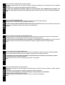
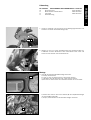
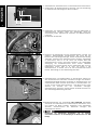
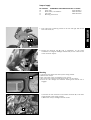
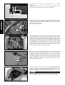
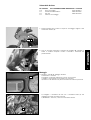
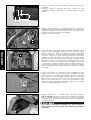
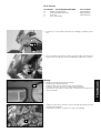
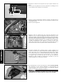
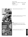
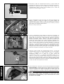
Information
Power Parts
KTM Teilenummer / Partnumber / Cod.art. / Référence / Número de la pieza KTM
601.12.035.044
10.2006
www.ktm.com
Art. 3.211.216
DEUTSCH
Danke, dass Sie sich für KTM Power Parts entschlossen haben.
Alle unsere Produkte wurden nach den höchsten Standards entwickelt und gefertigt, unter Verwendung der besten verfügbaren
Materialien.
KTM Power Parts sind rennerprobt und gewährleisten ultimative Performance.
KTM KANN NICHT VERANTWORTLICH GEMACHT WERDEN FÜR FALSCHE MONTAGE ODER VERWENDUNG DIESES PRODUKTS. Bitte
befolgen Sie die Montageanleitung. Wenn bei der Montage Unklarheiten auftreten, wenden Sie sich bitte an eine KTM Fachwerkstätte.
Danke
ENGLISH
2
Thank you for choosing KTM Power Parts!
All of our products are designed and built to the highest standards using the finest materials available.
KTM Power Parts are race proven to offer the ultimate in performance.
KTM WILL NOT BE HELD LIABLE FOR IMPROPER INSTALLATION OR USE OF THIS PRODUCT. Please follow all instructions provided. If you
are unsure of any installation procedure, please contact a certified KTM dealer.
Thank you.
ITALIANO
2
Grazie per aver deciso di acquistare un prodotto KTM Power Parts.
Tutti i nostri prodotti sono stati sviluppati e realizzati secondo i massimi standard e con l'impiego dei migliori materiali disponibili.
Le KTM Power Parts sono collaudate nelle competizioni ed assicurano altissime prestazioni.
KTM NON PUÒ ESSERE RESA RESPONSABILE PER UN MONTAGGIO O USO IMPROPRIO DI QUESTO PRODOTTO. Per favore osservate le
istruzioni nel manuale d'uso.Se dovessero sorgere dei dubbi al montaggio, rivolgetevi ad un'officina specializzata KTM.
Grazie.
FRANCAIS
2
Nous vous remercions d'avoir choisi KTM Power Parts.
Tous nos produits ont été développés et réalisés selon les plus hauts standards et en utilisant les meilleurs matériaux disponibles.
Les Power Parts de KTM ont fait leurs preuves en compétition et garantissent les meilleures performances.
LA RESPONSABILITÉ DE KTM NE SAURAIT ÊTRE ENGAGÉE EN CAS D'ERREUR DANS LE MONTAGE OU L'UTILISATION DE CE PRODUIT.
Il convient de respecter les instructions de montage.
Si quelque chose n'est pas clair lors du montage, il faut s'adresser à un agent KTM.
Merci
ESPANOL
2
2
Gracias por haberse decidido por el Power Parts KTM.
Todos nuestros productos han sido desarrollados y producidos según los estándares más altos utilizando los mejores materiales
disponibles.
Las KTM Power Parts están probadas en competencia y garantizan un óptimo rendimiento.
NO SE PUEDE HACER RESPONSABLE A LA KTM POR UN MONTAJE O UN USO INCORRECTO DE ESTE PRODUCTO.
Le rogamos seguir las instrucciones para el montaje.
Si durante el montaje resultan confusiones le rogamos contactar a un taller especializado KTM.
Gracias.
60112035044
BEFESTIGUNGSKIT FÜR ALARMANLAGE 601.12.035.000
2x
Druckverschluss
60112035010
1x
REED Schalter selbstklebend
60012035185
1x
LED Kabel
60012035190
1x
Anbauanleitung
DEUTSCH
Lieferumfang
3
1. Lösen Sie zunächst links und rechts die 5 Befestigungsschrauben und
entfernen Sie beide Seitenverkleidungen (1).
1
2. Hängen sie nun mit einem Schraubenzieher die Haltelasche (2) aus,
schwenken Sie dann Windschild samt Scheinwerfer nach vorne und
ziehen Sie den Stecker vom Steckerboard ab.
2
Montage
3
3. LED (3) des Alarmanlagenkabelstrangs montieren.
a) Cockpit demontieren.
b) Loch mit 6,5 mm Durchmesser in das Cockpit bohren.
c) Haltehülse der LED abziehen und in das Cockpit stecken.
d) Die LED von hinten durch die Haltehülse stecken bis sie einrastet.
e) Stecker der LED mit dem freien Stecker (4) des Hauptkabelstranges
im Cockpitträger verbinden.
f) Cockpit, Scheinwerfer und Seitenverkleidungen montieren.
4
DEUTSCH
4
4. Staufachdeckel, Staufachmittelteil und Staufachunterteil demontieren.
5. Kantenschutz des Staufachunterteils entfernen und eine Ausnehmung
für das Kabel der Alarmanlage laut Skizze schaffen.
10 mm
17 mm
12 mm
6. Kabelbinder vom Alarmanlagenkabelstrang lösen und Kabelstrang im
Staufachunterteil verlegen. Kabel der Alarmanlage durch die
Ausnehmung führen, Kantenschutz aufstecken und Staufachunterteil
montieren.
7. Blindstecker (1) abziehen.
1
8. Rückseite der Alarmanlage und das Staufachunterteil reinigen und
entfetten. Selbstklebenden Druckverschluss (2) mittig auf der
Rückseite der Alarmanlage anbringen. Zweiten Druckverschluss bündig
andrücken. Schutzfolie des Druckverschlusses abziehen, Alarmanlage
so positionieren, dass sie an der linken und vorderen Wand des
Staufachunterteils anliegt und kräftig anpressen. Bei sachgemäßer
Anbringung des Druckverschlusses reicht dessen Haltekraft
vollkommen aus. Optional können Sie die Alarmanlage aber auch mit
Kabelbindern sichern. Dazu ist es nötig, vier Löcher in das
Staufachunterteil zu bohren, durch die Sie die Kabelbinder führen
können. Alarmanlage mit dem Kabelstrang verbinden.
2
9. Staufachmittelteil und Staufachdeckel in demontiertem Zustand mit
dem Schnellverschluss verbinden. Innenseiten reinigen und entfetten.
Selbstklebenden REED Schalter (mit Kabel) im Staufachmittelteil und
selbstklebenden REED Schalter (ohne Kabel) im Staufachdeckel (ca.
20 mm von der hinteren Kante gemessen - siehe Bild) und mit einem
Abstand
von
maximal
4-5
mm
zueinander
anbringen.
Staufachmittelteil montieren und den Stecker des REED Schalters mit
dem Alarmanlagenkabelstrang verbinden.
20 mm
10.Bedienungsanleitung der Alarmanlage 601.12.035.000 aufmerksam
durchlesen und anschließend eine Funktionsprobe durchführen. Auch
die Funktion des REED Schalters üperprüfen. Dazu Alarmanlage
aktivieren, Schnellverschluss des Staufaches entriegeln und
Staufachdeckel anheben.
Handsender der Alarmanlage bereithalten, um sie jederzeit
ausschalten zu können, da der Schallpegel der Alarmsirene 114 dBA
beträgt.
Scope of supply
1. First loosen the 5 retaining screws on the left and right and remove
both side covers (1).
1
ENGLISH
60112035044
MOUNTING KIT FOR ALARM SYSTEM 601.12.035.000
2x
Velcro tape
60112035010
1x
REED switch, self-adhesive
60012035185
1x
LED cable
60012035190
1x
Mounting instructions
5
2. Detach the retaining tab (2) with a screwdriver, tilt the entire
windshield including the headlight forward and pull the connector out
of the connector support.
2
Mounting
3
3. Mount the LED (3) for the alarm system wiring harness.
a) Remove the cockpit.
b) Drill a hole with a 6.5 mm diameter in the cockpit.
c) Pull off the LED connector bushing and insert it in the cockpit.
d) Insert the LED through the connector bushing from behind until it
engages.
e) Connect the LED connector to the vacant connector (4) in the main
wiring harness of the cockpit support.
f) Mount the cockpit, headlight and side covers.
4
4.
Remove the lid, center section and lower section of the storage
compartment.
5. Remove the edge protection on the lower storage compartment and
provide a recess for the alarm system cable as illustrated.
10 mm
17 mm
12 mm
ENGLISH
6. Loosen the cable ties on the alarm system wiring harness and install
the cables in the lower storage compartment. Run the alarm system
cables through the recess, attach the edge protection and mount the
lower storage compartment.
7. Remove the dummy plug (1).
1
6
8. Clean and degrease the back of the alarm system and the lower storage
compartment. Center the self-adhesive Velcro tape (2) on the back of
the alarm system. Press the second Velcro tape against it. Remove the
protective film on the Velcro tape, position the alarm system so it rests
against the left and front wall of the lower storage compartment and
press together firmly. If the Velcro tape is correctly mounted, it should
be strong enough to hold the alarm system in place. You can also hold
the alarm system in place with cable ties. First drill four holes in the
lower storage compartment and insert the cable ties through the holes.
Connect the alarm system to the wiring harness.
2
9. Connect the center storage compartment and lid with the quick release
while still dismounted. Clean and degrease on the inside. Mount the
self-adhesive REED switch (with cable) in the center storage
compartment and the self-adhesive REED switch (without the cable) in
the storage compartment lid (measured approx. 20 mm from the rear
edge - see photo) no more than 4-5 mm apart. Mount the center
storage compartment and connect the REED switch connector to the
alarm system wiring harness.
20 mm
10.Carefully read the alarm system owner's manual 601.12.035.000 and
perform a functional check. Also make sure the REED switch works
correctly (activate the alarm system, unlock the quick release on the
storage compartment and lift the storage compartment lid).
Keep the handheld transmitter for the alarm system handy to be able
to turn it off quickly since the siren has a sound level of 114 dBA.
Volume della fornitura
60112035044
KIT DI FISSAGGIO ALLARME ANTIFURTO 601.12.035.000
N. 2
velcro di fissaggio
60112035010
N. 1
contatto reed autoadesivo
60012035185
N. 1
cavo led
60012035190
N. 1
istruzioni di montaggio
1. Svitare a destra ed a sinistra le cinque viti di fissaggio e togliere i due
rivestimenti laterali (1).
2. Con un cacciavite sganciare la linguetta di fissaggio (2), ribaltare in
avanti lo schermo completo di faro e staccare il connettore dal
portaconnettori.
2
ITALIANO
1
7
Montaggio
3
3. Montare il led (3) del cablaggio antifurto.
a) Smontare il cruscotto.
b) Eseguire un foro dal diametro di 6,5 mm nel cruscotto.
c) Sfilare il porta led dal led ed inserirlo nel cruscotto.
d) Inserire il led da dietro nel porta led finché non scatta in posizione.
e) Collegare il connettore del led con il connettore libero (4) del
cablaggio principale nel porta cruscotto.
f) Rimontare il cruscotto, il faro ed i rivestimenti laterali.
4
4. Smontare il coperchio, la parte centrale e la parte inferiore del vano
portaoggetti.
5. Togliere il profilo di protezione della parte inferiore del vano
portaoggetti e praticare un'apertura per il cavo dell'antifurto come da
schizzo.
10 mm
17 mm
12 mm
6. Aprire la fascetta serracavi del cablaggio dell'antifurto e sistemare il
cablaggio nella parte inferiore del vano portaoggetti. Far passare il cavo
dell'antifurto attraverso l'apertura, applicare il profilo di protezione e
rimontare la parte inferiore del vano portaoggetti.
7. Togliere il connettore cieco (1).
1
ITALIANO
8. Pulire e sgrassare il lato posteriore della centralina d'allarme e la parte
inferiore del vano portaoggetti. Applicare il velcro autoadesivo (2) in
posizione centrale sul retro della centralina d'allarme. Posizionarvi
sopra il secondo pezzo di velcro e premerlo giù per accoppiarlo bene
col primo. Togliere la striscia protettiva, posizionare la centralina
d'allarme in modo che aderisca alla parete sinistra ed alla parete
anteriore della parte inferiore del vano portaoggetti e premerla giù per
farla attaccare bene. Con un'applicazione corretta del velcro, la sua
adesività è sufficiente per assicurare un buon fissaggio. In alternativa
si può fissare la centralina d'allarme anche con fascette serracavi. A
questo scopo è necessario praticare quattro fori nella parte inferiore
del vano portaoggetti per far passare le fascette. Collegare la centralina
al cablaggio.
2
8
9. Unire la parte centrale e il coperchio del vano portaoggetti allo stato
smontato mediante la chiusura rapida. Pulire e sgrassare le pareti
interne. Attaccare il contatto reed autoadesivo (parte con cavo) nella
parte centrale del vano portaoggetti e l'altra parte del contatto reed
(senza cavo) nel coperchio (a ca. 20 mm dal bordo posteriore - vedi
foto) con una distanza di max. 4-5 mm tra di loro. Montare la parte
centrale del vano portaoggetti e collegare l'interruttore del contatto
reed con il cablaggio dell'allarme antifurto.
20 mm
10.Leggere attentamente il manuale d'uso dell'allarme antifurto
601.12.035.000 ed eseguire una prova di funzionamento. Controllare
anche il funzionamento del contatto reed. A questo scopo attivare
l'allarme antifurto, sbloccare la chiusura rapida del vano portaoggetti e
sollevare il coperchio.
Tener pronto il telecomando dell'antifurto per poter spegnerlo in
qualsiasi momento, perché la potenza acustica della sirena d'allarme è
di 114 dBA.
Kit de livraison
60112035044
KIT DE FIXATION POUR ALARME
2x
bandes auto-agrippantes
1x
contacteur REED autocollant
1x
fil de LED
1x
notice de montage
601.12.035.000
60112035010
60012035185
60012035190
1. Enlever les 5 vis de fixation des flancs de carénage et déposer ceux-ci
(1).
1
2. Avec un tournevis décrocher la patte de fixation (2), faire basculer le
saute-vent et le phare vers l'avant et débrancher la prise de la console.
Montage
3
3. Monter la LED (3) du faisceau de l'alarme
a) Démonter la planche de bord.
b) Percer dans celle-ci un trou de 6,5 mm de diamètre.
c) Retirer la douille de la LED et l'enfiler dans la planche.
d) Enfiler la LED dans la douille par en dessous de manière à ce
qu'elle s'enclipse.
FRANCAIS
2
9
e) Relier la prise de la LED avec la prise libre (4) du faisceau principal
au niveau de la planche.
f) Remonter la planche, le phare et les flancs de carénage.
4
4. Démonter le couvercle du vide-poche ainsi que la partie centrale et le
fond.
5. Retirer le joint de protection du fond et découper un passage pour le
fil de l'alarme comme indiqué sur l'illustration.
10 mm
17 mm
12 mm
6. Retirer le collier du faisceau de l'alarme et mettre le faisceau dans le
fond du vide-poche. Faire passer le fil par la découpe, remettre le joint
et remonter le fond.
7. Retirer la prise borgne (1).
1
8. Nettoyer le dos de l'alarme ainsi que le fond du vide-poche et les
dégraisser. Fixer la bande auto-agrippante (2) autocollante au milieu
du dos de l'alarme. Appliquer dessus, bord à bord, l'autre bande autoagrippante. Retirer la feuille de protection de la bande et fixer l'alarme
sur le fond du vide-poche de manière à ce qu'elle soit dans le coin
avant gauche. Appuyer fermement. Si le montage est fait proprement,
la bande auto-agrippante suffit largement. En option on peut aussi
mettre des colliers rilsan, mais il faut alors percer quatre trous dans le
fond du vide-poche afin de les passer. Relier l'alarme au faisceau.
2
FRANCAIS
9. Accrocher ensemble avec l'attache rapide la partie centrale et le
couvercle du vide-poche, toujours démontés. Nettoyer et dégraisser les
parois intérieures. Fixer le contacteur REED autocollant (avec le câble)
sur la partie centrale et le contacteur REED autocollant (sans câble)
sur le couvercle (à environ 20 mm du bord arrière ; voir illustration).
La distance entre les deux doit être de 4-5 mm au maximum.
Remonter la partie centrale du vide-poche et brancher la prise du
contacteur REED sur le faisceau de l'alarme.
20 mm
10
10.Lire attentivement la notice d'utilisation de l'alarme 601.12.035.000
puis effectuer un test. Vérifier également le fonctionnement du
contacteur REED. Pour cela activer l'alarme, puis décrocher l'attache
rapide du vide-poche et soulever le couvercle.
Il faut avoir la commande de l'alarme sous la main pour intervenir
immédiatement car le niveau sonore de la sirène est de 114 dBA.
Volumen de suministro
60112035044
JUEGO DE FIJACIÓN PARA EL DISPOSITIVO DE ALARMA
601.12.035.000
2 Cierres a presión
60112035010
1 Interruptor REED autoadhesivo
60012035185
1 Cable LED
60012035190
1 Instrucciones de montaje
1. Desatornille primeramente los 5 tornillos de fijación a la izquierda y a
la derecha y retire ambos revestimientos laterales (1).
1
2. Ahora descuelgue el cubrejunta de soporte (2) con un destornillador,
gire después el escudo protector del viento junto con el faro hacia
adelante y quite la terminal del tablero de la terminal.
2
Montaje
e) Conectar la terminal del LED con la terminal libre (4) del tramo
principal de cables en el soporte de la carlinga.
f) Montar la carlinga, el faro y los revestimientos laterales.
4
ESPANOL
3
3. Montar el LED (3) del tramo de cables del dispositivo de alarma.
a) Desmontar la carlinga.
b) Taladrar un hueco con un diámetro de 6,5 mm en la carlinga.
c) Quitar el manguito de soporte del LED y colocarlo en la carlinga.
d) Enchufar el LED por detrás a través del manguito de soporte hasta
que éste engatille.
11
4. Desmontar la tapa del compartimiento auxiliar, la parte central del
compartimiento auxiliar y la parte inferior del compartimiento auxiliar.
5. Desmontar la protección de los bordes de la parte inferior del
compartimiento auxiliar y hacer una escotadura para el cable del
dispositivo de alarma según el croquis.
10 mm
17 mm
12 mm
6. Soltar la abrazadera de cable del tramo de cables del dispositivo de
alarma y tender el tramo de cables en la parte inferior del
compartimiento auxiliar. Pasar el cable del dispositivo de alarma a
través de la escotadura, colocar la protección de los bordes y montar la
parte inferior del compartimiento auxiliar.
7. Retirar la clavija inactiva (1).
1
8. Limpiar y desengrasar la parte trasera del dispositivo de alarma y la
parte inferior del compartimiento auxiliar. Fijar el cierre autoadhesivo a
presión (2) en el centro de la parte trasera del dispositivo de alarma.
Apretar el segundo cierre a presión a ras. Sacar la lámina de
protección del cierre a presión, colocar el dispositivo de alarma de tal
manera que tenga contacto con la pared izquierda y delantera de la
parte inferior del compartimiento auxiliar y apretarla fuertemente. Si el
cierre a presión está colocado de manera adecuada, su fuerza de
retención es completamente suficiente. Pero opcionalmente puede
asegurarse el dispositivo de alarma también con abrazaderas de cable.
Para ello es necesario taladrar cuatro huecos en la parte inferior del
compartimiento auxiliar para poder pasar las abrazaderas de cable.
Conectar el dispositivo de alarma con el tramo de cable.
2
20 mm
ESPANOL
12
9. Conectar la parte central del compartimiento auxiliar y la tapa del
compartimiento auxiliar en estado desmontado con el cierre rápido.
Limpiar y desengrasar los lados interiores. Colocar el interruptor
autoadhesivo REED (con el cable) en la parte central del
compartimiento auxiliar y el interruptor autoadhesivo REED (sin el
cable) en la tapa del compartimiento auxiliar (a una distancia de
aprox. 20 mm del borde trasero - véase la fotografía) y colocarlos con
una distancia de máx. 4-5 mm entre el uno y el otro. Montar la parte
central del compartimiento auxiliar y conectar el interruptor REED con
el tramo de cables del dispositivo de alarma.
10.Leer atentamente el manual de instrucciones del dispositivo de alarma
601.12.035.000 y enseguida efectuar una prueba de funcionamiento.
Comprobar también el funcionamiento del interruptor REED. Para ello
activar el dispositivo de alarma, desbloquear el cierre rápido del
compartimiento auxiliar y levantar la tapa del compartimiento auxiliar.
Tener listo el emisor manual del dispositivo de alarma para poder
desconectarlo en todo momento, ya que el nivel acústico de la sirena
de alarma es de 114 dBA.