1
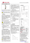
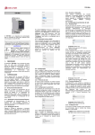
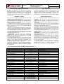
DIR2
Manual de Instrucciones
Instruction Manual
M98231501-20-10C
REGULADOR DE ENERGÍA REACTIVA DIR2
DIR2 PF Regulator
El DIR2 es un regulador de un solo paso de muy reducidas
dimensiones, ideal para compensar el cos ϕ en instalaciones
que requieren una regulación en un solo escalón. Puede
emplearse también como complemento de un regulador de
más pasos, ya sea como relé de alarma o para conectar un
paso adicional.
The DIR2 is a PF regulator to control a single capacitor step. The
DIR2 is the ideal regulator for cos ϕ compensation in small
installations where a single step regulation is required. The
regulator can be also used as alarm relay in case of lack of
compensation or as additional step in an existing capacitor bank.
CONEXIÓN Y AJUSTES
CONNECTION AND SETUP
Para la conexión y puesta en marcha del relé DIR2, deben
tenerse en cuenta los siguientes puntos :
- El relé DIR2 requiere la instalación de un transformador de
corriente eficiente de la serie MC1 (In / 0,25 A), donde In
debe ser mayor que la intensidad total de los receptores
instalados en la línea a compensar.
- El transformador de corriente se instalará en un punto de la
acometida por el que circule la totalidad de la intensidad de la
línea a compensar, pero sin leer la intensidad propia del
condensador (ver fig.1).
- Conectar el secundario del transformador de corriente (entre
borne 1S1 y borne 1S2, 2S1 ó 2S2, según el valor de primario
de corriente adecuado a la máxima corriente de la instalación)
en los bornes señalizados como S1 y S2 en el DIR2.
- La tensión de alimentación del regulador DIR2 debe tomarse
entre fases (habitualmente entre las fases L2 y L3) y debe
conectarse a los bornes A1-A2.
- IMPORTANTE: La fase donde está instalado el
transformador de intensidad, (normalmente L1), no debe
coincidir con las fases de las que se toma la tensión de
alimentación (normalmente L2-L3).
- La intensidad reactiva de disparo del relé se fija en el mando
frontal. El relé conecta cuando la intensidad reactiva medida
supera el valor marcado. Para evitar fluctuaciones en la
operación, el relé desconecta cuando la intensidad reactiva
medida baja por debajo del 70% de dicho valor.
- Si el relé no conecta y hay carga suficiente en la instalación,
revisar las conexiones, y si son correctas, probar a
intercambiar entre sí las conexiones que van a los terminales
S1 y S2 del DIR2.
To connect the DIR2 PF regulator, the following steps must be
considered:
- The DIR2 regulator requires one efficient current transformer
of MC1 type (In / 0.25 A). The primary current In must be
greater than the maximum current expected at the load to be
compensated.
- The current transformer must be placed in the line supplying
the load to be compensated. It must measure the load current,
excluding the capacitor current (see fig. 1)
- Connect the CT secondary terminals (between terminal 1S1
and terminal 1S2, 2S1 or 2S2, with the primary side value fitted
to the maximum value of the current drawn by the loads) to the
DIR2 terminals designated as S1-S2.
- The supply voltage of the DIR2 regulator must be taken phase
to phase (usually from phases L2 and L3) and connected to
terminals A1-A2).
- IMPORTANT: The phase where CT is placed (usually L1)
must not coincide with any of the phases used for the regulator
supply (usually L2 and L3)
- The reactive current at which the regulator trips is set by means
of the frontal knob. The output relay is activated when the
measured reactive current exceeds the set value. To avoid relay
flickering, the relay is deactivated when the current goes below
the 70% of the set value.
- If the DIR2 relay does not connect when it is expected,
(considerable reactive current at the load), review the
connections and check if it connects when reversing the
connections of CT secondary side to S1-S2 terminals.
CARACTERISTICAS TÉCNICAS / TECHNICAL CHARACTERISTICS
Tensión de alimentación : Fase - Fase
Frecuencia
Consumo
400 V ±10%
50-60 Hz
< 3 VA
Circuito de intensidad
Corriente nominal
Sobrecarga permanente
Consumo
Current circuit
0,25 A c.a. / a.c.
1,2 In
< 0,05 VA
Corriente reactiva de disparo
Margen de ajuste del disparo: C/K
Retardo de conexión Tc
Retardo de desconexión Tr
Protección al choque eléctrico
Rated current
Maximum permanent overload
Power consumption
Reactive tripping current
0,15 ... 2
Ver ejemplo / See example
5s
2s
Relé de salida
Corriente térmica Ith
AC11 Ie / Ue
DC11 Ie / Ue
Vida mecánica
Vida eléctrica
Condiciones ambientales
Temperatura de trabajo
Humedad relativa máxima sin condensación
Altitud máxima de funcionamiento
Otras características:
Indicación de conexión:
Verde: Alimentación, Rojo: Relé conectado
Fijación sobre perfil
Categoría de protección de la caja
Peso
Supply voltage : Phase to Phase
Frequency
Power consumption
Tripping adjustment range: C/K
Connection delay Tc
Disconnection delay Tr
Output relay
10 A
10 A / 250 V c.a. / a.c.
0,3 A / 110 V c.c. / d.c
10⋅106 maniobras / operations
10⋅104 maniobras / operations
-10º a +50 ºC
95 %
2000 m (s.n.m.) / 2000 m (AMSL)
LED: Verde / Rojo
Green / Red LED
DIN 46277 (EN 50022)
IP 40
0,25 kg
doble aislamiento clase II /
class II double isolation
Thermal current Ith
AC11 Ie / Ue
DC11 Ie / Ue
Mechanical endurance
Electrical endurance
Environment conditions
Working temperature
Maximum relative humidity without condensation
Maximum operation altitude
Other characteristics
Connection indication:
Green : Supply, Red: Relay ON
Rail fastening
Enclosure protection category
Weight
Electric shock protection
Categoría de instalación
Categoria III / Category III
Installation category
Normas
EN 61010, EN 61000-3-2,
EN 61000-3-3, EN 50081-2,
EN 50082-1, EN 50082-2,
EN 61000-4-2, EN 61000-4-4,
EN 61000-4-8, EN 61000-4-5,
EN 61000-4-11, UL 94
Standards
EJEMPLO AJUSTE VALOR C/K
C/K =
EXAMPLE C/K VALUE SETUP
Ic
K
C/K =
Ic
K
Ic = Corriente nominal del condensador
Ic = Nominal current of the capacitor
K = (Corriente de primario del TC) / 5
K = (Primary current of the CT) / 5
Ejemplo:
Example:
150
TC = 150/0,25 A ; K =
= 30
5
CT = 150/0.25 A ; K =
Condensador: 25 kvar / 440 V
150
= 30
5
Capacitor: 25 kvar / 440 V
25000
Ic 32,8
IC =
= 32,8 A ; C/K = =
= 1.1
1,73 × 440
K
30
IC =
25000
Ic 32,8
= 32,8 A ; C/K = =
= 1.1
1,73 × 440
K
30
DIMENSIONES / DIMENSIONS
TERMINALES Y CONEXIÓN / TERMINALS AND WIRING
TC/CT (…/250 mA)
73
L1
35
L2
CARGAS
L3
LOADS
68
A2
0,
5
A1
67
S2
0,1
5
85
S1
45
N
DIR2
C/K
1
2
16
1,
5
15
18
Fig. 1. Colocación del TC y conexión del DIR2
CT placement and DIR2 connections
¡PELIGRO RIESGO ELÉCTRICO!
ELECTRIC SHOCK HAZARD!
Una conexión incorrecta del equipo puede producir la
muerte, lesiones graves y riesgo de incendio. Cualquier
manipulación de este equipo debe ser realizada por personal
cualificado, y cumpliendo estrictamente todas las
normativas vigentes sobre seguridad.
Si el equipo es utilizado de una manera que no esté
especificado por el fabricante, la protección asegurada por
el equipo, puede verse comprometida.
El equipo debe estar provisto de interruptor magneto-térmico o
equivalente para desconectarlo. De igual forma deberá estar
provisto de fusibles tipo gl (IEC 269) o tipo M de entre 0,5 y 2 A.
El circuito de alimentación del equipo se conectará con cable de
sección mínima 1.5 mm2.
Death, serious injury, or fire hazard could result from
improper connection of this instrument. Installation,
operation, and maintenance of this instrument must be
performed by qualified personnel only.
If the equipment is handled in a way not specified by the
manufacturer, the equipment's protection may be
compromised.
Servicio Técnico
Technical Service
En caso de cualquier duda de funcionamiento o avería del equipo consulte
www.circutor.es o avisar al servicio técnico de Circutor S.A
Vial Sant Jordi, s/n
08232 - Viladecavalls
tel - 93 745 29 00 & fax - 93 745 29 14
E-mail : [email protected]
For any inquiry or in case of malfunction, see www.circutor.es or contact with technical
service of Circutor S.A
Vial Sant Jordi, s/n
08232 - Viladecavalls (SPAIN)
Telephone: + 34 93 7452900 FAX: + 34 93 7452914
E-mail : [email protected]
The device has to be provided with a miniature circuit breaker to
be disconnected. The fuses has to be type gl (IEC 269) or type
M between 0.5 to 2 A. The power supply circuit will be connected
with a wire with a minimum cross-section of 1.5 mm2.