1
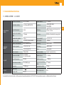
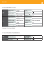
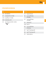
Ref. 563101
ES
EN
DVBS2 - COFDM
DVBS2 - COFDM
Manual de Instrucciones
User manual
w w w. t e l e v e s . c o m
DVBS2 - COFDM
Índice
6.
7.
8.
9.
Características técnicas .....................................................................................................................
Descripción de referencias .................................................................................................................
Montaje ...............................................................................................................................................
3.1. Montaje en libro ...........................................................................................................................
3.2. Montaje en rack 19” ....................................................................................................................
Descripción de elementos ..................................................................................................................
4.1. Introducción .............................................................................................................................
4.2. Fuente de alimentación ............................................................................................................
4.3. Central amplificadora ..............................................................................................................
4.4. Programador universal .............................................................................................................
Instrucciones de uso ..........................................................................................................................
5.1. Menú normal ............................................................................................................................
5.2. Menú extendido ........................................................................................................................
Control del dispositivo .......................................................................................................................
Ejemplo de distribución de 7 canales de DVBS2-COFDM T0X .........................................................
Normas para montaje en rack ............................................................................................................
Normas para montaje en cofre ...........................................................................................................
5
7
8
8
9
10
10
11
12
13
14
14
16
18
20
21
23
A.
Tabla de canales .................................................................................................................................
47
4.
5.
ES
ESPAÑOL
1.
2.
3.
5
1. Características técnicas
1.1. DVBS2-COFDM
Desmodulador
Satélite
Modulador
COFDM
Salida RF
General
ref. 563101
Frecuencia de entrada:
950 - 2150 MHz
Pérdidas de paso:
< 1,5 dB tip.
Velocidad de símbolo:
10-30 Mbaud (QPSK- 8PSK)
Modulación:
DVB-S2 (QPSK, 8PSK)
DVB-S (QPSK)
Pasos de frecuencia:
1 MHz
FEC interno:
LDPC (9/10, 8/9, 5/6, 4/5, 3/4, 2/3, 3/5,
1/2, 1/4, 1/3, 2/5)
Conectores de entrada y
salida:
“F” hembra
FEC externo:
BCH (Bose-Chaudhuri-Hocquenghem)
Impedancia de entrada:
75 ohm.
Factor de roll-off
20%, 25%, 35%
Alimentación LNB:
13/17V/ OFF 22KHz (ON/OFF)
R.O.E. entrada:
10 dB min.
Formato de modulación:
QPSK, 16QAM, 64QAM
Scrambling:
DVB ET300744
Intervalo de guarda:
1/4, 1/8, 1/16, 1/32
Interleaving:
DVB ET300744
FEC:
1/2, 2/3, 3/4, 5/6, 7/8
Cell_id:
Seleccionable
Ancho de banda:
7 MHz, 8 MHz
Espectro de salida:
Normal / Invertido (Selec.)
Frecuencia de salida:
45- 862 MHz
474 - 858 MHz (UHF)
Pérdidas de paso:
< 1,5 dB tip.
Pasos de frecuencia:
166 KHz
Pérdidas de retorno:
> 12 dB tip.
Nivel máximo de salida:
80±5 dBμV (progr.)
Conectores de entrada y
salida:
“F” hembra.
Atenuación:
>15 dB (prog)
Impedancia de salida:
75 ohm.
Alimentación:
24V
Consumo 24V:
300 mA
Indice de protección:
IP20
Las características técnicas descritas se definen para una temperatura ambiente de 40°C (108ºF). Para temperaturas superiores se utilizará ventilación forzada.
ES
DVBS2 - COFDM
6
1.2. Características técnicas Centrales
Central
5575
Central
451202
(1) Canal principal
Rango de frecuencia:
46 ... 862 MHz
Conector:
Ganancia:
44 ± 2,5 dB
Alimentación:
“F”
Margen de regulación:
20 dB
Consumo a 24 V
Tensión de salida (60 dB):
105 dBμV (42 CH CENELEC)
Toma de test:
-30 dB
Rango de frecuencia (1):
47 ... 862 MHz
Conector:
“F”
Ganancia (1):
40 - 53 dB (selec.)
Alimentación:
230 V~
Tensión máx. de salida (1):
129 dBμV (tip.) (DIN 45004B)
Consumo dispositivo:
600 mA @ 9Vdc / 600 mA @ 12Vdc
Rango de frecuencia (2):
5 ... 30 MHz
Toma de test:
-20 dB
Ganancia (2):
20/ -3 dB (tip.)
Tensión máx. de salida (2):
129/ --- dBμV (tip.) (DIN 45004B)
24 V
:
450 mA
(2) Canal retorno (activo/pasivo)
1.3. Características técnicas Fuente Alimentación
Fuente
alimentación
5629
Tensión de entrada:
196 - 264 V~ 50/60 Hz
Corriente máxima total
(salida1 + salida2):
24V
(5 A)
Tensión de salida:
24V
Corriente máx. por salida:
24V
(4 A)
7
2. Descripción de referencias
Gama
563101
Accesorios
DVBS2-COFDM T0X
7234
Programador Universal
5575
Central Amplif. T0X (46 - 862 MHz)
5071
451202
Central DTKom (47 - 862 MHz)
Soporte carril DIN 498mm
(8 T0X + Alim.)
555901
Control de Cabecera T0X
5239
Soporte carril DIN 560mm
(9 T0X + Alim.)
5629
Fuente alimentación (196-264 V~ - 50/60 Hz)
- 5 A)
(24 V
5301
Anillo subrack 19”
507202
Cofre T0X
5069
Soporte carril DIN 648 mm
(10 T0X + Alim.)
4061
Carga “F” 75 ohm bloqueada DC
4058
Carga “F” 75 ohm bloqueada DC
5334
Unidad de ventilación
ES
DVBS2 - COFDM
8
3. Montaje
3.1. Montaje en libro
5629
Entrada F.I
Satélite
563101
5575
BROADBAND AMPLIFIER
DVBS 2-COFDM
DVBS 2-COFDM
DVBS 2-COFDM
DVBS 2-COFDM
DVBS 2-COFDM
DVBS 2-COFDM
CLAC!
TEST
(-30dB)
5071
5239
PRGM
PRGM
PRGM
1
Salida
COFDM
4061
A
B
C
7234
NOTA: Se recomienda utilizar ambas salidas de la fuente, equilibrando el consumo. Por ejemplo, 4+3 o 3+4 módulos.
2
9
3.2. Montaje en Rack 19”
CTRL
CTRL
CTRL
PWR
CTRL
BROADBAND AMPLIFIER
PWR
DVBS2-COFDM
PWR
DVBS2-COFDM
PWR
DVBS2-COFDM
PWR
DVBS2-COFDM
DVBS2-COFDM
DVBS2-COFDM
ES
PWR
CTRL
TEST
(-30dB)
PWR
CTRL
5301
PRGM
PRGM
PRGM
PRGM
PRGM
PRGM
02340039001 003
02340043001
003
02340043001
003
02340043001
003
02340043001
003
02340043001
003
02340043001
003
02340038001
NOTA: La fuente de alimentación puede alimentar un máximo de siete módulos DVBS2-COFDM T0X.
002
DVBS2 - COFDM
10
4. Descripción de elementos
1
2
DVBS2-COFDM
4.1. Introducción
5
PWR
CTRL
3
4
El transmodulador DVBS2 a COFDM recibe un
transpondedor de satélite en alguno de los formatos de modulación DVBS (QPSK) o DVBS2 (QPSK o
8PSK) y lo desmodula obteniendo un paquete de
transporte MPEG-2.
6
8
PRGM
02340043001
7
1. Entrada F.I. Satélite
2. Salida F.I. Satélite
3. Entrada RF
4. Salida RF
5. Entrada alimentación módulo
6. LED de estado
7. Conector BUS de control
8. Conector programador / PC
003
Posteriormente el paquete de transporte MPEG2
es modulado en formato COFDM y convertido al
canal de salida (UHF o VHF y ancho de banda máximo de 8 MHz) utilizando un up-converter ágil.
Mediante el programador universal (ref. 7234) se
realiza la programación de los parámetros de funcionamiento del transmodulador (frecuencia de
entrada, canal de salida, formato de modulación y
adaptación de servicios principalmente).
11
4.2. Fuente de alimentación
DVBS2-COFDM
(1)
Conectores para
alimentar los
módulos (1)
CTRL
LED de estado
24V
24V
0V
24V
0V
24V
PWR
24V: OK
0V: Sobrecarga o cortocircuito
02340039001 003
Entrada RED
230V~
NOTA: La fuente de alimentación puede alimentar un máximo de siete módulos DVBS2-COFDM T0X.
ES
DVBS2 - COFDM
12
4.3. Central amplificadora
OPCIÓN “A” - 5575
BROADBAND AMPLIFIER
1
2
OPCIÓN “B” - 451202
TEST
(-30dB)
PWR
6
+10 dB
5
20 dB
On
20 dB
10 dB
OK - MATV
10 dB
20 dB
MATV
OK - Return
USO EXCLUSIVO EN INTERIOR
FOR INDOOR USE ONLY
C. Ret
C. Ret
¡¡¡ATENCIÓN!!!
NO ABRIR. TENSIONES ELEVADAS DENTRO
¡¡¡WARNING!!!
DO NOT OPEN. LIVE PARTS INSIDE
I. max 150mA
196-264V~ 50/60Hz
Fuse: T1A L 250V
02340019 002
MATV
Ret.
OUT
Test IN
-20 dB
Test OUT
-20 dB
Ret.
IN
MATV
7
3
4
1
1. Salida RF
2. Toma Test
3. Entrada RF
4. Entrada RF
5. Entrada alimentación módulo
6. Atenuador
7. LED de estado
Dispone de dos conectores de entrada de señal, para permitir la mezcla de los
canales suministrados por dos sistemas. Si se utiliza sólo una de las entradas, se
recomienda cargar la entrada no utilizada con una carga de 75 ohm, ref 4061.
Dispone de un conector de salida y una toma de Test (-30dB) situadas en la
parte superior del panel frontal.
La alimentación se realiza a 24V, a través de un latiguillo igual al utilizado para
la alimentación de los otros módulos del sistema.
2
3 4
5
6 7
1. Entrada alimentación red (196-264 V~ 50/60 Hz)
2. Conexión para toma de tierra
3. LED de encendido
4. Entrada MATV
Salida canal de retorno
5. Test entrada MATV
6. Test salida MATV
7. Salida MATV
Entrada canal de retorno
La central amplificadora realiza la amplificación de los canales generados en los transmoduladores, cubriendo el margen de frecuencias de 47 a 862 MHz.
13
4.4. Programador Universal
El programador consta de 4 teclas:
(pulsación corta) - Selección de parámetro
(posicionamiento del cursor).
PCT 4.0
-
UNIVER
Modificación del parámetro (incremento/
decremento) apuntando por el cursor (parpadeante).
SAL
(pulsación corta) - Cambio de menú.
A
B
(pulsación larga) - Cambio entre menús principales y extendidos.
C
(pulsación larga) - Grabado de configuración
en memoria.
+
+
Aumentar el contraste de la pantalla.
+
+
Disminuir el contraste de la pantalla.
ES
DVBS2 - COFDM
14
5. - Instrucciones de uso
5.1. Menú Normal
b. Menú de modulación COFDM1
Insertar el programador en el conector frontal de
programación del módulo (“PRGM”). Aparecerá en
primer lugar la versión de firmware del programador:
a. Menú de Entrada
El siguiente menú principal permite seleccionar
varios parámetros de la modulación COFDM de
salida:
PCT firmware
version
El primer menú principal permite seleccionar la
frecuencia de entrada, la velocidad de símbolo
de la señal de entrada y la alimentación del conversor LNB (0, 13v22KHz, 13v, 17v22KHz o 17v).
-----------V:5.3
A continuación se muestra la versión de firmware
del módulo DVBS2-COFDM:
Version
Firmware
Unidad:
1.00.00016
ENTRADA
Frec.: 1234MHz
27.500 Kbaud
LNB:13V22KHz
Para realizar una modificación se deberá pulsar la
tecla hasta que el parámetro deseado parpadee.
Seguidamente se podrá modificar dicho campo
mediante las teclas y .
El rango de valores permitidos para la frecuencia
de entrada es 950-2150 MHz, mientras que para la
velocidad de símbolo el rango es 10 a 30 Mbaud.
En caso de “corto” en el conector de entrada (alimentación del LNB habilitada) parpadea el led del
frontal del módulo hasta que desaparezca esta
condición.
COFDM
>>
8MHz
64QAM
GI:1/8
FEC:3/4
Los parámetros seleccionables en este menú y sus
posibles valores son los siguientes:
• Ancho de banda de la señal COFDM: 7MHz
u 8MHz.
• Modulación: QPSK, 16QAM o 64QAM.
• Intervalo de guarda: 1/4, 1/8, 1/16 o 1/32.
• FEC: 1/2, 2/3, 3/4, 5/6 o 7/8.
15
c. Menú de modulación COFDM 2
En el siguiente menú principal se puede seleccionar el parámetro cell_id (identificador de celda) de
la modulación COFDM:
COFDM
Cell_id:
0x0000
d. Menú salida
El siguiente menú principal muestra la frecuencia o canal de salida, el offset de salida (sólo en
modo canal), el control del nivel y la selección de
inversión de espectro de salida.
SALIDA
Ch:C21 Of:0
(474.000 MHz)
Niv:99 Norm.
SALIDA
Frec: 474.000
Nivel: 99
IQ: Norm.
Para modificar la frecuencia se deberá pulsar la tecla hasta que el parámetro deseado parpadee.
Seguidamente se podrá modificar dicho campo
mediante las teclas y .
En modo frecuencia se permite seleccionar cualquier valor de frecuencia de salida entre 177,5 226,5 MHz (VHF) y 474 - 858 MHz (UHF). La parte
decimal depende del salto de frecuencia que se
escoja (ver menú extendido a). Si se selecciona un
salto de 125 KHz los valores permitidos para la
parte decimal son 0, 125, 250, 375, 500, 625, 750 y
875 KHz. En caso de tener un salto de 166 KHz los
valores posibles son 0, 166, 333, 500, 666 y 833 KHz.
El control de nivel de salida admite valores entre
00 y 99.
Los posibles valores para la inversión de espectro
de salida son “Norm.” (no invertido) e “Inv.” (inversión de espectro).
En modo canal se permite seleccionar un canal de
salida de la tabla seleccionada así como el offset
respecto a la frecuencia central del canal. Los valores permitidos de offset dependen del salto de frecuencia seleccionado (ver menú de configuración):
• Saltos de 125KHz: ±4 (-500, -375, -250, -125, 0 ,
125, 250, 375, 500 KHz)
• Saltos de 166KHz: ±3 (-500, -333, -166, 0 , 166,
333, 500 KHz).
e. Menú servicio
En este menú se muestra la lista de servicios del
transport stream seleccionado. Cada vez que el
usuario selecciona un nuevo transporte de entrada, la unidad realiza una búsqueda de los servicios.
Durante ese proceso la unidad mostrará el siguiente mensaje, indicando el número de servicios encontrados:
ES
SERVICIO
Scanning: 13
Una vez terminada la búsqueda se muestra la lista
de servicios con la siguiente información:
SERVICIO
2/8
18/25
France 2
OFF
Se indica el número de orden del servicio así como
el número total de servicios en el múltiplex (en la
figura servicio 2 de 8 disponibles), los estadísticos
(en la figura 18/25), el nombre del servicio y si el
usuario lo ha seleccionado para su eliminación en
la salida (OFF) o su paso a la salida sin modificar
(ON).
La indicación de los estadísticos es la siguiente:
el primer número indica el porcentaje de la salida
DVBS2 - COFDM
que ocupa el servicio indicado. El segundo número
indica el porcentaje de la salida que esta libre. En
el ejemplo France 2 ocuparía un 18% de la salida
(está a OFF por lo que se está eliminando) y hay un
25% de espacio libre. Podemos ver así fácilmente
que, en principio, se podría activar (ON) este servicio ya que aún hay capacidad suficiente a la salida.
El porcentaje libre a la salida solo se actualiza una
vez grabada la configuración de los servicios.
Adicionalmente se indica, en la esquina superior
derecha, el estado (embrollado o en claro) del servicio, a la entrada:
Servicio embrollado a la entrada.
16
g. Menú Medidas 2
5.2. Menú Extendido
Este menú indica la tasa de ocupación de la salida del módulo así como el máximo alcanzado. Si
se seleccionan demasiados servicios se producirá
un desbordamiento de la salida y se indicará esta
condición.
Cuando se mantiene pulsada la tecla
durante
más de 3 segundos la unidad muestra una serie de
menús de uso menos frecuente llamados menús
extendidos.
MEDIDAS
Ocupacion:
76%
Max:80%
MEDIDAS
Desbordamien
to!!
No se recomiendan valores de ocupación superiores al 82%. Este menú es de sólo lectura por lo que
no son operativas las teclas ni .
Se puede resetear el máximo de ocupación pulsando la tecla .
f. Menú Medidas 1
El siguiente menú proporciona una indicación de
la calidad de la señal de entrada mediante una estimación de la C/N (dB) y del link margin (dB).
MEDIDAS >>
C/N:14.1dB
L.M.: 7.7dB
a. Menú de Configuración
En este menú se permite la selección la dirección
de la unidad (para ser controlada a través de un
Control de Cabecera CDC).
También permite seleccionar el salto de frecuencia de salida (125 o 166KHz) y la tabla de canales
que se desea utilizar o bien modo de funcionamiento por frecuencia.
CONFIG.
Dir CDC: 001
Salto: 166KHz
CCIR N.Z.Ind
Las posibles tablas de canales seleccionables son:
• CCIR,
• China
• Chile
• Italia
• Francia
• Canales OIR
• Irlanda
• Sudáfrica
• Polonia
• Australia
17
b. Menú Identificadores
c. Menú medida de Temperatura
d. Menú de Versiones
Algunos receptores de DVB-T pueden presentar
problemas el recibir canales transmodulados que
comparten el mismo identificador (transport_
stream_id). Para evitar estos casos se permite que
el usuario cambie los siguientes identificadores del
múltiplex DVBT de salida: transport_stream_id (ts_
id), network_id (n_id) y original_network_id (on_id).
El siguiente menú proporciona una indicación de
la temperatura actual de la unidad así como el
máximo registrado. Es posible resetear el máximo
pulsando la tecla .
En este menú se muestran al usuario las versiones de firmware de la unidad y del modulador de
COFDM (FPGA).
Se puede escoger modo Auto (no se cambian los
identificadores) o modo Manual.
Al pasar de modo Auto a Manual se muestran los
identificadores recibidos de satélite y el usuario
puede cambiarlos.
MEDIDAS
Act:
04
Max:
05
reset
VERSION
Unidad:
1.00.00016
1.00.00017
ES
Los márgenes de funcionamiento recomendados
son los siguientes:
• Funcionamiento óptimo : 0-6
• Temperatura alta: 7-8
NIT IDs
Auto
IDs Manual
ts_id: 0x04fc
n_id: 0x055f
on_id: 0x055f
e. Menú LCN
• Temperatura excesiva: 9-10
En caso de que el máximo registrado esté fuera del
margen óptimo debería modificarse la instalación
para intentar reducir la temperatura.
Si ha instalado los módulos DVBS2-COFDM en un
cofre ref. 5069 y la temperatura de alguno de los
módulos esta fuera del margen óptimo de funcionamiento, se deberá instalar la unidad de ventilación ref. 5334. Para comprobar si este cambio es
efectivo se puede resetear el máximo y comprobar
su valor pasado un cierto tiempo.
Permite asignar un LCN (Logical Channel Number)
(entre 1 y 1023) a los servicios presentes en la salida (los marcados como ON o DCY).
LCN
1/4
Fashion TV
N:0003
LCN
3/4
Soyuz TV
NO LCN
Para modificar el LCN se usarán las teclas y o
. Si se selecciona “0000” como LCN se mostrará
“NO LCN”.
DVBS2 - COFDM
18
f. Menú Idioma
5.3. Grabación de parámetros
El último menú extendido permite seleccionar el
idioma de los menús (español / inglés / alemán /
francés):
IDIOMA
Una vez escogido el valor deseado en cualquiera
de los menús (normal o extendido), para grabar
los datos se pulsará la tecla durante aproximadamente 3 segundos. El display mostrará la siguiente
indicación:
~
Espanol
Pulsando las teclas
leccionado.
y
se cambia el idioma se-
Grabando los
Parametros y
Rearrancando
...
Si se modifican los datos de configuración pero no
se graban, se recupera la configuración anterior
transcurridos unos 30 segundos, es decir, se anulan
los cambios realizados.
6. - Control del dispositivo
Esta versión del DVBS2-COFDM T0X permite la configuración y monitorización desde un PC, tanto de
forma local como remota.
a. Control local
Es necesario disponer del programa “Gestión de
Cabeceras” (v2.13 o superior) y de un cable especial (proporcionado con dicho programa) que conecta un puerto serie de PC al conector “PRGM” del
DVBS2-COFDM T0X.
Desde el programa se pueden configurar y leer todos los parámetros de funcionamiento, así como
monitorizar el correcto funcionamiento del dispositivo..
b. Control remoto
Es necesario disponer de un módulo de Control de
Cabecera (ref. 555901) que incluye el programa
mencionado anteriormente, y del correspondiente
módem conectado a la línea telefónica.
Una vez establecida la comunicación con el control
de cabecera se podrá acceder a todos los dispositivos controlables que se hayan instalado en la
cabecera. En este caso es indispensable que cada
elemento esté programado con una dirección de
dispositivo distinta entre 1 y 254.
19
Esquema de Menús
ENTRADA
Frec.: 1234 MHz
27.500 Kbaud
LNB:13V22KHz
CONFIG.
Dir CDC: 001
Salto: 166KHz
CCIR N.Z.Ind
COFDM
>>
8MHz
64QAM
GI:1/8
FEC:3/4
IDs Manual
ts_id: 0x04fc
n_id: 0x055f
on_id: 0x055f
Pulsacion
´
larga
COFDM
Cell_id:
0x0000
MEDIDAS
Act:
04
Max:
05
SALIDA
Ch:C21 Of:0
(474.000 MHz)
Niv:99 Norm.
VERSION
Unidad:
1.00.00016
1.00.00017
SERVICIO
2/8
18/25
France 2
OFF
LCN
1/4
Fashion TV
N:0003
MEDIDAS >>
C/N:14.1dB
L.M.: 7.7dB
MEDIDAS
Ocupacion:
76%
Max:80%
reset
IDIOMA
Espa¤ol
ES
DVBS2 - COFDM
20
7. Ejemplo de aplicación
Distribución de 7 canales de DVBS2-COFDM T0X
DVBS2-COFDM
DVBS2-COFDM
DVBS2-COFDM
DVBS2-COFDM
DVBS2-COFDM
DVBS2-COFDM
DVBS2-COFDM
75 ohm
4061
4512
5629
7 x 563101
Salida COFDM
En la ilustración se muestra el montaje para la distribución de 7 canales de DVBS2-COFDM T0X.
21
8. Normas para montaje en rack (máx. 35 DVBS2-COFDM T0X - 7 subracks de 5u. de altura - 8,7”)
8.1. Instalación del rack con ventilación
Para favorecer la renovación y circulación del aire
en el interior del rack reduciendo de esta manera
la temperatura de las unidades y mejorando por
ello sus prestaciones, se recomienda colocar 2 unidades de ventilación de 25W de potencia, sobre
todo cuando el rack con el DVBS2-COFDM T0X se
encuentre en ambientes cálidos, superiores a 40°C.
Estos ventiladores irán colocados en una bandeja
atornillada en la parte superior del Rack, fig. 1 y 2,
de esta manera los ventiladores extraerán el aire
del DVBS2-COFDM T0X y lo expulsarán a través de
la rendija (unos 3-5 cm) que hay en la parte superior del Rack, por la parted inferior del dispositivo,
fig 3.
ES
Frontal
Subrack
fig. 1
fig. 2
fig. 3
DVBS2 - COFDM
22
8.2. Instalación del rack sin ventilación
Es muy importante que este ciclo discurra correctamente, debiendo evitarse:
- Abrir las puertas laterales, ya que provocaría que
los ventiladores aspiren el aire del exterior en lugar de aspirar el aire del interior.
Para la instalación de las unidades en racks sin ventilación, cuando el rack se encuentra en lugares
con temperatura ambiente alrededor de los 40°C,
se recomienda colocar el Rack completamente
abierto, es decir, prescindiendo de sus puertas laterales para favorecer la ventilación de las unidades , fig. 5.
- Colocar objetos junto al rack que taponen las entradas y salidas de aire.
- En los casos en que el rack no este completo, se
deben colocar los subracks de arriba a abajo sin
dejar huecos en el medio, fig 4.
fig. 4
fig. 5
23
9. Normas para montaje en cofre
IMPORTANTE
El esquema de ventilación recomendado es el de la figura tanto en
caso de disposición horizontal como
vertical de los cofres.
Si la temperatura ambiente en el
recinto es superior a 40º se instalará
la unidad de ventilación Ref. 5334
en la parte inferior de cada cofre.
La temperatura máxima en las
proximidades del cofre situado a
mayor altura no debe ser superior
a 45ºC, tanto si la disposición de
los cofres es horizontal como
vertical.
EXTRACTOR para
ventilación forzada.
Obligatorio sobre
módulo más alto.
ES
Disposición
Horizontal
Disposición
Vertical
Rejilla inferior en
cualquier pared.
DVBS2 - COFDM
24
IMPORTANTE
1m
Se recomienda situar los cofres en horizontal, colocándolos a la menor altura
posible.
HORIZONTAL
En caso de no poder utilizar la colocación
horizontal, se empleará la colocación
vertical.
0,2 m
0,2 m
Se respetarán las distancias de seguridad
indicadas en los esquemas adjuntos.
0,8 m
Colocar a la menor
altura posible.
Máxima Tª:
45ºC.
0,2 m
VERTICAL
0,2 m
DVBS2 - COFDM
Index
6.
7.
8.
9.
Technical specifications ......................................................................................................................
Reference description .........................................................................................................................
Mounting .............................................................................................................................................
3.1. Wall mounting ..............................................................................................................................
3.2. 19” rack mounting ......................................................................................................................
Element description ............................................................................................................................
4.1. Introduction ..............................................................................................................................
4.2. Power supply unit .....................................................................................................................
4.3. Amplifier ..................................................................................................................................
4.4. Universal programmer .............................................................................................................
How to use the product ......................................................................................................................
5.1. Main menu ...............................................................................................................................
5.2. Extended menu .........................................................................................................................
5.3. Parameters saving ....................................................................................................................
Controlling the device ........................................................................................................................
Distribution of 7 channels of DVBS2-COFDM T0X .............................................................................
Norms for rack mounting ....................................................................................................................
Norms for cabinet mounting ...............................................................................................................
27
29
30
30
31
32
32
33
34
35
36
36
38
40
40
42
43
45
A.
Channels table ....................................................................................................................................
47
4.
5.
EN
ENGLISH
1.
2.
3.
27
1. Technical characteristics
1.1. DVBS2-COFDM
Satellite
Demodulator
COFDM
Modulator
RF output
ref. 563101
Input frequency:
950 - 2150 MHz
Through loss:
< 1,5 dB typ.
Symbol rate:
10-30 Mbaud (QPSK- 8PSK)
Modulation:
DVB-S2 (QPSK, 8PSK)
DVB-S (QPSK)
Frequency steps:
1 MHz
Internal FEC:
LDPC (9/10, 8/9, 5/6, 4/5, 3/4, 2/3, 3/5,
1/2, 1/4, 1/3, 2/5)
Input connectors
and output:
“F” female
External FEC:
BCH (Bose-Chaudhuri-Hocquenghem)
Input impedance:
75 ohm.
Roll-off factor:
20%, 25%, 35%
LNB power supply:
13/17V/ OFF 22KHz (ON/OFF)
Input VSWR:
10 dB min.
Modulation format:
QPSK, 16QAM, 64QAM
Scrambling:
DVB ET300744
Guard interva:
1/4, 1/8, 1/16, 1/32
Interleaving:
DVB ET300744
FEC:
1/2, 2/3, 3/4, 5/6, 7/8
Cell_id:
Selectable
Bandwidth:
7 MHz, 8 MHz
Output spectrum:
Normal / Inverted (Selec.)
Output frequency:
45- 862 MHz
474 - 858 MHz (UHF)
Through loss:
< 1,5 dB typ.
Frequency steps:
166 KHz
Return loss:
> 12 dB typ.
80±5 dBμV (progr.)
Input and output
connectors:
“F” female.
Attenuation:
>15 dB (prog)
Output impedance:
75 ohm.
Power supply:
24V
Consumption 24V:
300 mA
Protection index:
IP20
Maximum output level:
General
The technical characteristics described are defined for a maximum ambient temperature of 40°C (108ºF). Forced ventilation is used for higher temperatures.
EN
DVBS2 - COFDM
28
1.2. Technical specs. Broaband Amplifiers
Amplifier
5575
Amplifier
451202
(1) Main channel
Frequency range:
46 ... 862 MHz
Connector:
“F”
Gain:
44 ± 2,5 dB
Power supply:
24 V
Regulation margin:
20 dB
Consumption at 24 V
Output level (60 dB):
105 dBμV (42 CH CENELEC)
Test socket:
-30 dB
Frequency range (1):
47 ... 862 MHz
Connector:
“F”
Gain (1):
40 - 53 dB (selec.)
Power supply:
230 V~
Maximum output level (1):
129 dBμV (typ.) (DIN 45004B)
Device consumption:
600 mA @ 9Vdc / 600 mA @ 12Vdc
Frequency range (2):
5 ... 30 MHz
Test socket:
-20 dB
Gain (2):
20/ -3 dB (typ.)
Maximum output level (2):
129/ --- dBμV (typ.) (DIN 45004B)
:
450 mA
(2) Return channel (active/passive)
1.3. Technical specs. Power Supply Unit
Power supply
5629
Mains voltage:
196 - 264 V~ 50/60 Hz
Total max. current
(outpur 1 + output 2):
24V
(5 A)
Output voltage:
24V
Max voltage per output:
24V
(4 A)
29
2. Description of references
Range
563101
Accessories
DVBS2-COFDM T0X
7234
Universal Programmer
5575
Amplifier T0X (46 - 862 MHz)
5071
451202
Amplifier DTKom (47 - 862 MHz)
Wall Support 498mm
(8 T0X + P.S.U.)
555901
Headend control T0X
5239
Wall Support 560mm
(9 T0X + P.S.U.)
5629
Power supply unit (196-264 V~ - 50/60 Hz)
(24 V
- 5 A)
5301
Subrack 19”
507202
Cabinet T0X
5069
Wall Support 648 mm
(10 T0X + P.S.U.)
4061
75 ohm adapter load “F” blocked
4058
75 ohm adapter load “F” blocked
5334
Ventilation unit
EN
DVBS2 - COFDM
30
3. Mounting
3.1. Wall mounting
5629
IF satellite
input
563101
5575
BROADBAND AMPLIFIER
DVBS 2-COFDM
DVBS 2-COFDM
DVBS 2-COFDM
DVBS 2-COFDM
DVBS 2-COFDM
DVBS 2-COFDM
CLAC!
TEST
(-30dB)
5071
5239
PRGM
PRGM
PRGM
1
Output
COFDM
4061
A
B
C
7234
NOTE: The use of both source outputs is recommended, balancing the consumption. For example, 4+3 or 3+4 modules
2
31
3.2. 19” rack mounting
CTRL
CTRL
CTRL
PWR
CTRL
BROADBAND AMPLIFIER
PWR
DVBS2-COFDM
PWR
DVBS2-COFDM
PWR
DVBS2-COFDM
PWR
DVBS2-COFDM
DVBS2-COFDM
DVBS2-COFDM
EN
PWR
CTRL
TEST
(-30dB)
PWR
CTRL
5301
PRGM
PRGM
PRGM
PRGM
PRGM
PRGM
02340039001 003
02340043001
003
02340043001
003
02340043001
003
02340043001
003
02340043001
003
NOTE: The power source can supply a maximum of seven DVBS2-COFDM T0X modules
02340043001
003
02340038001
002
DVBS2 - COFDM
32
4. Identification of the system elements
1
2
DVBS2-COFDM
4.1. Introduction
5
PWR
CTRL
3
4
The DVBS2 transmodulator with COFDM receives
a satellite transponder in some DVBS (QPSK) or
DVBS2 (QPSK or 8PSK) modulation formats and
demodulates it by obtaining an MPEG-2 transport
package.
8
PRGM
02340043001
7
6
1. IF satellite input
2. IF satellite output
3. RF input
4. RF output
5. Module power supply input
6. Status LED
7. Control BUS connector
8. Programmer / PC connector
003
The MPEG2 transport package is then modulated
in COFDM format and converted to the output
channel (UHF or VHF and with a maximum
bandwidth of 8 MHz) using an agile up-converter.
The programming of the transmodulator operating
parameters (input frequency, output channel,
modulation format and adaptation of services
mainly) is performed through the universal
programmer (ref. 7234).
33
4.2. Power supply unit
DVBS2-COFDM
(1)
Connectors
to power the
modules (1)
CTRL
On LED
24V
24V
0V
24V
0V
24V
EN
PWR
24V: OK
0V: Overload or short circuit
02340039001 003
Mains input
230V~
NOTE: The power source can supply a maximum of seven DVBS2-COFDM T0X modules.
DVBS2 - COFDM
34
4.3. Broadband amplifier
OPTION “A” - 5575
BROADBAND AMPLIFIER
1
2
OPTION “B” - 451202
TEST
(-30dB)
PWR
6
+10 dB
5
20 dB
On
20 dB
10 dB
OK - MATV
10 dB
20 dB
MATV
OK - Return
USO EXCLUSIVO EN INTERIOR
FOR INDOOR USE ONLY
C. Ret
C. Ret
¡¡¡ATENCIÓN!!!
NO ABRIR. TENSIONES ELEVADAS DENTRO
¡¡¡WARNING!!!
DO NOT OPEN. LIVE PARTS INSIDE
I. max 150mA
196-264V~ 50/60Hz
Fuse: T1A L 250V
02340019 002
MATV
Ret.
OUT
Test IN
-20 dB
Test OUT
-20 dB
Ret.
IN
MATV
7
3
4
1
1. RF output
2. Test socket
3. RF input
4. RF input
5. Module power supply input
6. Status LED
7. Attenuator
It has two signal input connectors, to allow the mixture of the channels
provided by two systems. If only using one of the inputs, it is recommended to
load the unused input with a load of 75 ohm, ref 4061.
It has an output connector and a test socket (-30 dB) located in the upper part
of the front panel.
The power supply is achieved with 24V, through a cable that is the same as that
used to supply power for the system’s other modules.
2
3 4
5
6 7
1. Mains power supply input (196-264 V~ 50/60 Hz)
2. Ground connection
3. Power LED
4. MATV input
Return channel output
5. MATV input test
6. MATV output test
7. MATV output
Return channel input
The broadband amplifier amplifies the channels generated in the transmodulators, covering the frequency margins from 47 to 862 MHz
35
4.4. Universal Programmer
The programmer consists of 4 buttons:
(short press) - Selection of parameter
(positioning of the cursor).
PCT 4.0
-
UNIVER
Modification of the parameter chosen by
the cursor (flashing)
SAL
(short press) - Change menu
(long press) - Change between Principal
and Extended menus
A
B
C
(long press) - Save changes to memory
+
+
Increases the contrast of the screen.
+
+
Decreases the contrast of the screen.
EN
DVBS2 - COFDM
36
5. - Instructions for use
5.1. Normal menu
b. COFDM1 modulation menu
Insert the programmer in the front connector of
the module programming (“PRGM”). First, the
programmer’s firmware version will appear:
a. Input menu
The next main menu allows various COFDM output
modulation parameters to be selected:
PCT firmware
version
------------
The first main menu lets you select the input
frequency, the symbol rate of the input signal
and the power supply of the LNB converter
(0, 13v22KHz, 13v, 17v22KHz or 17v).
V:5.3
The firmware version of the DVBS2 – COFDM
module is shown below:
Unit
Firmware
version:
1.00.00016
INPUT
Freq.: 1234MHz
27.500 Kbaud
LNB:13V22KHz
To make a change press the key until the desired
parameter flashes. This field can be then be
changed by means of the keys and .
The range of values allowed for the input frequency
is 950-2150 MHz, whereas for the symbol rate the
range is 10 to 30 Mbaud.
In case of a ‘short-circuit’ in the input connector
(power supply enabled for the LNB) the LED on
the front of the module flashes until this condition
disappears.
COFDM
>>
8MHz
64QAM
GI:1/8
FEC:3/4
The parameters that can be selected in this menu
and their possible values are as follows:
• Bandwidth of the COFDM signal: 7MHz or
8MHz.
• Modulation: QPSK, 16QAM or 64QAM.
• Guard interval: 1/4, 1/8, 1/16 or 1/32.
• FEC: 1/2, 2/3, 3/4, 5/6 or 7/8.
37
c. COFDM2 modulation menu
In the next main menu you can select the
parameter cell_id (cell identifier) of the COFDM
modulation:
COFDM
Cell_id:
0x0000
d. Output menu
The next main menu shows the frequency or
output channel, the output offset (only in channel
mode), the level control and the selection of
output spectrum inversion.
OUTPUT
Ch:C21 Of:0
(474.000 MHz)
Lev:99 Norm.
OUTPUT
Freq: 474.000
Level: 99
IQ: Norm.
(VHF) and 474 - 858 MHz (UHF). The decimal part
depends on the difference of frequency chosen
(see extended menu b). If you select a difference of
125 KHz the permitted values for the decimal part
are 0, 125, 250, 375, 500, 625, 750 and 875 KHz.
With a difference of 166 KHz the possible values
are 0, 166, 333, 500, 666 and 833 KHz.
The output level control permits values between
00 and 99.
The possible values for the output spectrum
inversion are “Norm.” (not inverted) and ‘Inv.’
(spectrum inversion).
In channel mode it lets you select an output
channel from the table selected as well as the offset
regarding the channel’s receiving point frequency.
The permitted offset values depend on the
frequency difference selected (see configuration
menu):
• Steps of 125KHz: ±4 (-500, -375, -250, -125, 0 ,
125, 250, 375, 500 KHz)
• Steps of 166KHz: ±3 (-500, -333, -166, 0 , 166,
333, 500 KHz).
e. Service menu
This menu shows the list of transport stream
services selected. Each time the user selects a new
input transport, the unit performs a search for the
services.
During that process the unit will display the
following message, indicating the number of
services found:
SERVICE
Scanning: 13
Once the search is complete, it shows the list of
services with the following information:
SERVICE
2/8
18/25
France 2
OFF
To change the frequency press the key until the
desired parameter flashes. This field can be then be
changed by means of the keys and .
The service order number as well as the total
number of services in the multiplex (in service
figure 2 of 8 available) are indicated, the statistics
(in the figure 18/25), the name of the service and
if the user has selected it for removal in the output
(OFF) unscrambling (DCY) or to move it to output
without changing (ON).
In frequency mode you can select any output
frequency value between 177.5 - 226.5 MHz
The meaning of the statistics is as follows: the first
number indicates the percentage of the output
EN
DVBS2 - COFDM
that occupies the service indicated. The second
number indicates the percentage of the output
that is free. In the example, France 2 will occupy
18% of the output (it is OFF so it is removed) and
there is 25% of free space. It is easy to see that,
in principle, this service could be activated (ON
or DCY) because there is still sufficient capacity
to output. The free percentage to output is only
updated once the configuration of the services has
been recorded.
Additionally, the status (scrambled or clear) of the
service, both at the input and output are indicated
in the upper right hand corner:
Scrambled service at input.
38
g. Measurements menu 2
5.2. Extended menu
This menu indicates the occupancy rate of the
module’s output as well as the maximum achieved.
If too many services are selected it will result in an
output overflow and this condition is indicated.
When the
key is held down for more than 3
seconds the unit shows a series of less frequently
used menus called extended menus.
MONITOR
Occupancy:
76%
Max:80%
MONITOR
Overflow!!
Occupancy values higher than 82% are not
recommended. This is a read only menu, which
disables the keys and .
You can reset the maximum occupation by
pressing the key .
a. Configuration menu
This menu enables the address of the unit to be
selected (to be controlled through a CDC Headend
Control).
It also allows selection of the output frequency
difference (125 or 166KHz), the table of channels
to use or frequency mode operation.
CONFIG.
CDC Adr: 001
Step: 166KHz
CCIR N.Z.Ind
f. Measurements menu 1
The following menu provides an indication of the
input signal quality using an estimate of C/N (dB)
and the link margin (dB).
MONITOR >>
C/N:14.1dB
L.M.: 7.7dB
The channel tables that can be selected are:
• CCIR,
• China
• Chile
• Italy
• France
• OIR channels
• Ireland
• South Africa
• Poland
• Australia
39
b. Identifier menu
Some DVB-T receivers can present problems
receiving transmodulator channels which share
the same identifier (transport_stream_id). To avoid
these cases the user can change the following DVBT
output multiplex identifiers: transport_stream_id
(ts_id), network_id (n_id) and original_network_id
(on_id).
You can choose Auto mode (the identifiers do not
change) or Manual mode.
When switching from Auto mode to Manual the
identifiers received by satellite are displayed and
the user can change them.
c. Temperature measurement
menu
d. Versions menu
The following menu provides an indication of
the unit’s current temperature as well as the
maximum recorded. The maximum can be reset by
pressing the key .
In this menu the user is shown the firmware
versions for the unit and the COFDM (FPGA)
modulator.
MONITOR
Now:
04
Max:
05
VERSION
Unit:
1.00.00016
1.00.00017
EN
reset
The recommended operating margins are as
follows:
• Optimum operation : 0-6
NIT IDs
Auto
IDs Manual
ts_id: 0x04fc
n_id: 0x055f
on_id: 0x055f
• High temperature: 7-8
• Excessive temperature: 9-10
If the maximum recorded is outside the optimal
range the installation should be adjusted to try to
lower the temperature.
If the DVBS2-COFDM modules have been installed
in a housing ref. 5069 and the temperature of one
of the modules is outside of the optimal operating
range, the ventilation unit will have to be installed
ref. 5334. To check whether this change is effective
the maximum can be reset and its value checked
after a given time.
e. LCN menu
Assign a LCN (Logical Channel Number) (between
1 and 1023) to the existing services at the output
(marked as ON or DCY).
LCN
1/4
Fashion TV
N:0003
LCN
3/4
Soyuz TV
NO LCN
To change the LCN press keys and or
lect “0000” as LCN will show “NO LCN”.
. If se-
DVBS2 - COFDM
40
f. Language menu
The last extended menu enables the menu
language to be selected (Spanish / English /
German / French):
LANGUAGE
English
Pressing keys
language.
and
changes the selected
5.3. Parameters saving
6. - Controlling the Device
Once a parameter is modified to the desired value
in any menu (normal or extended), to save the
settings press for three seconds. The display will
show the following indication:
This version of the DVBS2-COFDM T0X allows
configuration and monitoring via a PC, both locally
and remotely.
Saving
settings and
restarting
...
If the configuration paremeters are modified but
not saved, the previous configuration is retrieved
after 30 sec. in other words, the changes are
discarded.
a. Local control
The “Headend Management” programme (v2.13
or higher) is required, as well as a special cable
(provided with the programme) that connects a
PC serial port to the DVBS2-COFDM T0X “PRGM”
connector.
The programme can be used to set up and read all
the operating parameters, as well as to monitor the
correct operation of the device.
b. Remote control
It is necessary to have a Headend Control module
(ref. 555901) that includes the programme
mentioned above, and the corresponding modem
connected to a phone line.
Once the communication with the headend
control has been established, all the controllable
devices that have been installed in the headend
can be accessed. In this case it is essential that each
element be programmed with a different device
address between 1 and 254.
41
Menu structure
INPUT
Freq.: 1234 MHz
27.500 Kbaud
LNB:13V22KHz
CONFIG.
CDC Adr: 001
Step: 166KHz
CCIR N.Z.Ind
COFDM
>>
8MHz
64QAM
GI:1/8
FEC:3/4
IDs Manual
ts_id: 0x04fc
n_id: 0x055f
on_id: 0x055f
Long press
´
COFDM
Cell_id:
0x0000
MONITOR
Now:
04
Max:
05
OUTPUT
Ch:C21 Of:0
(474.000 MHz)
Lev:99 Norm.
VERSION
Unit:
1.00.00016
1.00.00017
SERVICE
2/8
18/25
France 2
OFF
LCN
1/4
Fashion TV
N:0003
MONITOR >>
C/N:14.1dB
L.M.: 7.7dB
MONITOR
Occupancy:
76%
Max:80%
reset
LANGUAGE
English
EN
DVBS2 - COFDM
42
7. Application example
Distribution of 7 channels of DVBS2-COFDM T0X
DVBS2-COFDM
DVBS2-COFDM
DVBS2-COFDM
DVBS2-COFDM
DVBS2-COFDM
DVBS2-COFDM
DVBS2-COFDM
75 ohm
4061
4512
5629
7 x 563101
COFDM output
The diagram shows the assembly for the distribution of 7 channels of DVBS2-COFDM T0X
43
8. Norms for rack mounting (max. 35 DVBS2-COFDM T0X - 7 subracks with 5 units in height - 8,7”)
8.1. Installation of the rack with
ventilation facilities
To facilitate the renewal and circulation of the
air inside the rack, and the temperature of the
units and thus improve their characteristics, it
is advisable to place 2 ventilation units of 25W,
particularly when the rack with the DVBS2-COFDM
T0X is located in warm place, with a temperature
higher than 40°C.
These ventilators will be placed on a tray, that is
screwed onto the top part of the Rack, fig. 1 and
2, and in this way the ventilators will be able to
extract the air from the DVBS2-COFDM T0X and
will be able to expel it via the gap (approx. 3-5 cm)
at the top part of the Rack. The air will enter again
through the lower part of the device, fig 3.
EN
Frontal
Subrack
fig. 1
fig. 2
fig. 3
DVBS2 - COFDM
44
8.2. Installation of the rack without
ventilation facilities
It is very important that this process operates
correctly, therefore the following must be
observed:
- Do not open the side doors, as this would cause
the ventilators to extract the air from the outside
rather than the air in the inside of the rack.
To install the units in racks without installation
facilities, and when the rack is located in a place
with a temperature of around 45°C, it is advisable
to place the rack completely open, in other words,
do not use the side doors. This is to facilitate the
ventilation of the units , fig. 5.
- Do not place objects close to the rack that may
block the entry and exit points of the air.
- If the rack is not complete, the subracks must be
placed from the top downwards without leaving
any gaps in between, fig. 4.
fig. 4
fig. 5
45
9. Norms for cabinet mounting
IMPORTANT
The scheme of recommended
ventilation is the one in the figure
in any case of cabinet placement
(horizontal or vertical).
EXTRACTOR for forced
ventilation must be onto
the highest module.
EN
If the ambient temperature in the
room is above 40 º C, will install the
ventilation unit Ref. 5334 in the
bottom of each module.
Horizontal
placement
The maximum temperature
permitted surrounding the highest
cabinet is 45ºC in both ways of
placement, horizontal or vertical
way.
Vertical
placement
Inferior grid in
any wall.
DVBS2 - COFDM
46
IMPORTANT
1m
Horizontal placement of the cabinets is
strongly recommended, hanging them
with as less height as possible.
HORIZONTAL
If the horizontal placement is impossible,
then vertical placement is allowed.
Respect the recommended minimum
distances in the attached schemes.
0,2 m
0,2 m
0,8 m
Maximum T:
45ºC.
Place the cabinets
with as less height as
possible
0,2 m
VERTICAL
0,2 m
47
A. Tabla de canales / Channels table
Tabla1
Tabla2
CCIR
China/Taiwan
C02
C03
C04
L01
L02
L03
S01
S02
S03
S04
S05
S06
S07
S08
S09
S10
C05
C06
C07
C08
C09
C10
C11
C12
S11
S12
S13
S14
S15
S16
S17
S18
S19
S20
S21
50,50
57,50
64,50
71,50
78,50
85,50
107,50
114,50
121,50
128,50
135,50
142,50
149,50
156,50
163,50
170,50
177,50
184,50
191,50
198,50
205,50
212,50
219,50
226,50
233,50
240,50
247,50
254,50
261,50
268,50
275,50
282,50
289,50
296,50
306,00
1
2
3
4
5
6
7
8
9
10
11
12
C21
C22
C23
C24
C25
C26
C27
C28
C29
C30
C31
C32
C33
C34
C35
C36
C37
C38
C39
C40
C41
C42
C43
52,50
60,50
68,50
80,00
88,00
171,00
179,00
187,00
195,00
203,00
211,00
219,00
474,00
482,00
490,00
498,00
506,00
514,00
522,00
530,00
538,00
546,00
554,00
562,00
570,00
578,00
586,00
594,00
602,00
610,00
618,00
626,00
634,00
642,00
650,00
Tabla3
Tabla4
Chile
1
2
3
4
5
6
7
8
9
10
11
12
21
22
23
24
25
26
27
28
29
30
31
32
33
34
35
36
37
38
39
40
41
42
43
57,00
63,00
69,00
79,00
85,00
177,00
183,00
189,00
195,00
201,00
207,00
213,00
473,00
479,00
485,00
491,00
497,00
503,00
509,00
515,00
521,00
527,00
533,00
539,00
545,00
551,00
557,00
563,00
569,00
575,00
581,00
587,00
593,00
599,00
605,00
Italia
A
B
C
S01
S02
S03
S04
S05
S06
S07
S08
S09
S10
D
E
F
G
H
H1
H2
S11
S12
S13
S14
S15
S16
S17
S18
S19
S20
S21
S22
S23
S24
S25
56,00
64,50
84,50
107,50
114,50
121,50
128,50
135,50
142,50
149,50
156,50
163,50
170,50
177,50
186,00
194,50
203,50
212,50
219,50
226,50
233,50
240,50
247,50
254,50
261,50
268,50
275,50
282,50
289,50
296,50
306,00
314,00
322,00
330,00
338,00
Tabla5
Francia
F01
L02
L03
L04
S01
S02
S03
S04
S05
S06
S07
S08
S09
S10
L05
L06
L07
L08
L09
L10
S11
S12
S13
S14
S15
S16
S17
S18
S19
S20
S21
S22
S23
S24
S25
45,00
53,00
57,75
61,00
107,50
114,50
121,50
128,50
135,50
142,50
149,50
156,50
163,50
170,50
178,75
186,75
194,75
202,75
210,75
218,75
233,50
240,50
247,50
254,50
261,50
268,50
275,50
282,50
289,50
296,50
306,00
314,00
322,00
330,00
338,00
Tabla6
Canales OIR
R01
R02
R03
R04
R05
S01
S02
S03
S04
S05
S06
S07
S08
R06
R07
R08
R09
R10
R11
R12
S11
S12
S13
S14
S15
S16
S17
S18
S19
S20
S21
S22
S23
S24
S25
52,50
62,00
80,00
88,00
96,00
114,00
122,00
130,00
138,00
146,00
154,00
162,00
170,00
178,00
186,00
194,00
202,00
210,00
218,00
226,00
234,00
242,00
250,00
258,00
266,00
274,00
282,00
290,00
298,00
306,00
314,00
322,00
330,00
338,00
346,00
Tabla7
Irlanda
1
2
3
5
6
7
8
9
10
11
C21
C22
C23
C24
C25
C26
C27
C28
C29
C30
C31
C32
C33
C34
C35
C36
C37
C38
C39
C40
C41
C42
C43
C44
C45
48,50
56,50
64,50
178,00
186,00
194,00
202,00
210,00
218,00
226,00
474,00
482,00
490,00
498,00
506,00
514,00
522,00
530,00
538,00
546,00
554,00
562,00
570,00
578,00
586,00
594,00
602,00
610,00
618,00
626,00
634,00
642,00
650,00
658,00
666,00
Tabla8
Suráfrica
2
3
4
5
6
7
8
9
10
11
12
13
C21
C22
C23
C24
C25
C26
C27
C28
C29
C30
C31
C32
C33
C34
C35
C36
C37
C38
C39
C40
C41
C42
C43
56,50
64,50
178,00
186,00
194,00
202,00
210,00
218,00
226,00
234,00
242,00
250,00
474,00
482,00
490,00
498,00
506,00
514,00
522,00
530,00
538,00
546,00
554,00
562,00
570,00
578,00
586,00
594,00
602,00
610,00
618,00
626,00
634,00
642,00
650,00
Tabla9
Polonia (OIR)
S01
S02
S03
S04
S05
S06
S07
S08
K06
K07
K08
K09
K10
K11
K12
S09
S10
S11
S12
S13
S14
S15
S16
S17
S18
S19
S20
S21
S22
S23
S24
S25
S26
S27
S28
114,00
122,00
130,00
138,00
146,00
154,00
162,00
170,00
178,00
186,00
194,00
202,00
210,00
218,00
226,00
234,00
242,00
250,00
258,00
266,00
274,00
282,00
290,00
298,00
306,00
314,00
322,00
330,00
338,00
346,00
354,00
362,00
370,00
378,00
386,00
Tabla10
Australia
0
1
2
3
4
5
S02
S03
S04
S05
5A
S06
S07
S08
S09
S10
6
7
8
9
9A
10-o
10
11-o
11
12
S11
S12
S13
S14
S15
S16
S17
S18
S19
50,50
59,50
66,50
88,50
97,50
104,50
114,50
121,50
128,50
135,50
140,50
142,50
149,50
156,50
163,50
170,50
177,50
184,50
191,50
198,50
205,50
211,50
212,50
218,50
219,50
226,50
233,50
240,50
247,50
254,50
261,50
268,50
275,50
282,50
289,50
DVBS2 - COFDM
S22
S23
S24
S25
S26
S27
S28
S29
S30
S31
S32
S33
S34
S35
S36
S37
S38
S39
S40
S41
C21
C22
C23
C24
C25
C26
C27
C28
C29
C30
C31
C32
C33
C34
C35
C36
C37
C38
C39
C40
C41
314,00
322,00
330,00
338,00
346,00
354,00
362,00
370,00
378,00
386,00
394,00
402,00
410,00
418,00
426,00
434,00
442,00
450,00
458,00
466,00
474,00
482,00
490,00
498,00
506,00
514,00
522,00
530,00
538,00
546,00
554,00
562,00
570,00
578,00
586,00
594,00
602,00
610,00
618,00
626,00
634,00
48
C44
C45
C46
C47
C48
C49
C50
C51
C52
C53
C54
C55
C56
C57
C58
C59
C60
C61
C62
C63
C64
C65
C66
C67
C68
C69
658,00
666,00
674,00
682,00
690,00
698,00
706,00
714,00
722,00
730,00
738,00
746,00
754,00
762,00
770,00
778,00
786,00
794,00
802,00
810,00
818,00
826,00
834,00
842,00
850,00
858,00
44
45
46
47
48
49
50
51
52
53
54
55
56
57
58
59
60
61
62
63
64
65
66
67
68
69
70
71
72
73
74
75
76
77
78
79
80
81
82
83
84
611,00
617,00
623,00
629,00
635,00
641,00
647,00
653,00
659,00
665,00
671,00
677,00
683,00
689,00
695,00
701,00
707,00
713,00
719,00
725,00
731,00
737,00
743,00
749,00
755,00
761,00
767,00
773,00
779,00
785,00
791,00
797,00
803,00
809,00
815,00
821,00
827,00
833,00
839,00
845,00
851,00
S26
S27
S28
S29
S30
S31
S32
S33
S34
S35
S36
S37
S38
S39
S40
S41
C21
C22
C23
C24
C25
C26
C27
C28
C29
C30
C31
C32
C33
C34
C35
C36
C37
C38
C39
C40
C41
C42
C43
C44
C45
346,00
354,00
362,00
370,00
378,00
386,00
394,00
402,00
410,00
418,00
426,00
434,00
442,00
450,00
458,00
466,00
474,00
482,00
490,00
498,00
506,00
514,00
522,00
530,00
538,00
546,00
554,00
562,00
570,00
578,00
586,00
594,00
602,00
610,00
618,00
626,00
634,00
642,00
650,00
658,00
666,00
S26
S27
S28
S29
S30
S31
S32
S33
S34
S35
S36
S37
S38
S39
S40
C21
C22
C23
C24
C25
C26
C27
C28
C29
C30
C31
C32
C33
C34
C35
C36
C37
C38
C39
C40
C41
C42
C43
C44
C45
C46
354,00
362,00
370,00
378,00
386,00
394,00
402,00
410,00
418,00
426,00
434,00
442,00
450,00
458,00
466,00
474,00
482,00
490,00
498,00
506,00
514,00
522,00
530,00
538,00
546,00
554,00
562,00
570,00
578,00
586,00
594,00
602,00
610,00
618,00
626,00
634,00
642,00
650,00
658,00
666,00
674,00
C46
C47
C48
C49
C50
C51
C52
C53
C54
C55
C56
C57
C58
C59
C60
C61
C62
C63
C64
C65
C66
C67
C68
C69
674,00
682,00
690,00
698,00
706,00
714,00
722,00
730,00
738,00
746,00
754,00
762,00
770,00
778,00
786,00
794,00
802,00
810,00
818,00
826,00
834,00
842,00
850,00
858,00
C44
C45
C46
C47
C48
C49
C50
C51
C52
C53
C54
C55
C56
C57
C58
C59
C60
C61
C62
C63
C64
C65
C66
C67
C68
C69
658,00
666,00
674,00
682,00
690,00
698,00
706,00
714,00
722,00
730,00
738,00
746,00
754,00
762,00
770,00
778,00
786,00
794,00
802,00
810,00
818,00
826,00
834,00
842,00
850,00
858,00
S29
S30
S31
S32
S33
S34
S35
S36
S37
S38
C21
C22
C23
C24
C25
C26
C27
C28
C29
C30
C31
C32
C33
C34
C35
C36
C37
C38
C39
C40
C41
C42
C43
C44
C45
C46
C47
C48
C49
C50
C51
394,00
402,00
410,00
418,00
426,00
434,00
442,00
450,00
458,00
466,00
474,00
482,00
490,00
498,00
506,00
514,00
522,00
530,00
538,00
546,00
554,00
562,00
570,00
578,00
586,00
594,00
602,00
610,00
618,00
626,00
634,00
642,00
650,00
658,00
666,00
674,00
682,00
690,00
698,00
706,00
714,00
S20
S21
S22
S23
S24
S25
S26
S27
S28
S29
S30
S31
S32
S33
S34
S35
S36
S37
S38
S39
S40
S41
S42
S43
S44
S45
H21
H22
H23
H24
H25
H26
H27
H28
H29
H30
H31
H32
H33
H34
H35
296,50
305,50
312,50
319,50
326,50
333,50
340,50
347,50
354,50
361,50
368,50
375,50
382,50
389,50
396,50
403,50
410,50
417,50
424,50
431,50
438,50
445,50
452,50
459,50
466,50
473,50
480,50
487,50
494,50
501,50
508,50
515,50
522,50
529,50
536,50
543,50
550,50
557,50
564,50
571,50
578,50
49
C42
C43
C44
C45
C46
C47
C48
C49
C50
C51
C52
C53
C54
C55
C56
C57
C58
C59
C60
C61
C62
C63
C64
C65
C66
C67
C68
C69
642,00
650,00
658,00
666,00
674,00
682,00
690,00
698,00
706,00
714,00
722,00
730,00
738,00
746,00
754,00
762,00
770,00
778,00
786,00
794,00
802,00
810,00
818,00
826,00
834,00
842,00
850,00
858,00
85
86
857,00
863,00
C46
C47
C48
C49
C50
C51
C52
C53
C54
C55
C56
C57
C58
C59
C60
C61
C62
C63
C64
C65
C66
C67
C68
C69
674,00
682,00
690,00
698,00
706,00
714,00
722,00
730,00
738,00
746,00
754,00
762,00
770,00
778,00
786,00
794,00
802,00
810,00
818,00
826,00
834,00
842,00
850,00
858,00
C46
C47
C48
C49
C50
C51
C52
C53
C54
C55
C56
C57
C58
C59
C60
C61
C62
C63
C64
C65
C66
C67
C68
C69
674,00
682,00
690,00
698,00
706,00
714,00
722,00
730,00
738,00
746,00
754,00
762,00
770,00
778,00
786,00
794,00
802,00
810,00
818,00
826,00
834,00
842,00
850,00
858,00
C47
C48
C49
C50
C51
C52
C53
C54
C55
C56
C57
C58
C59
C60
C61
C62
C63
C64
C65
C66
C67
C68
C69
682,00
690,00
698,00
706,00
714,00
722,00
730,00
738,00
746,00
754,00
762,00
770,00
778,00
786,00
794,00
802,00
810,00
818,00
826,00
834,00
842,00
850,00
858,00
C52
C53
C54
C55
C56
C57
C58
C59
C60
C61
C62
C63
C64
C65
C66
C67
C68
C69
722,00
730,00
738,00
746,00
754,00
762,00
770,00
778,00
786,00
794,00
802,00
810,00
818,00
826,00
834,00
842,00
850,00
858,00
H36
H37
H38
H39
H40
H41
H42
H43
H44
H45
H46
H47
H48
H49
H50
H51
H52
H53
H54
H55
H56
H57
H58
H59
H60
H61
H62
H63
H64
H65
H66
H67
H68
H69
H70
H71
H72
H73
H74
H75
585,50
592,50
599,50
606,50
613,50
620,50
627,50
634,50
641,50
648,50
655,50
662,50
669,50
676,50
683,50
690,50
697,50
704,50
711,50
718,50
725,50
732,50
739,50
746,50
753,50
760,50
767,50
774,50
781,50
788,50
795,50
802,50
809,50
816,50
823,50
830,50
837,50
844,50
851,50
858,50
DVBS2 - COFDM
50
Garantía
Televés S.A. ofrece una garantía de dos años calculados a partir de la fecha de compra para los países de la UE. En los países no miembros de la UE se
aplica la garantía legal que está en vigor en el momento de la venta. Conserve la factura de compra para determinar esta fecha.
Durante el período de garantía, Televés S.A. se hace cargo de los fallos producidos por defecto del material o de fabricación. Televés S.A. cumple la
garantía reparando o sustituyendo el equipo defectuoso.
No están incluidos en la garantía los daños provocados por uso indebido, desgaste, manipulación por terceros, catástrofes o cualquier causa ajena al
control de Televés S.A.
Guarantee
Televés S.A. offers a two year guarantee, beginning from the date of purchase for countries in the EU. For countries that are not part of the EU, the legal
guarantee that is in force at the time of purchase is applied. Keep the purchase invoice to determine this date.
During the guarantee period, Televés S.A. complies with the guarantee by repairing or substituting the faulty equipment.
The harm produced by improper usage, wear and tear, manipulation by a third party, catastrophes or any other cause beyond the control of Televés S.A.
is not included in the guarantee.
51