1
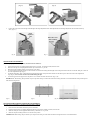
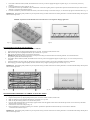
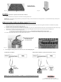
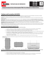
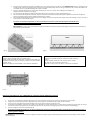
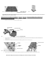
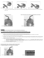
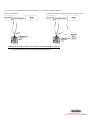
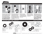
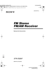
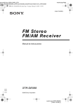
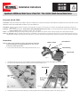
AG-4100 AG-4200 AG-4300 Installation Instructions AquaGuard® 4000 Series Water Sensor & Drain Port - Titan, Goliath, Goliath Furnace/Value Series Work Safe, READ THIS! ATTENTION: FAILURE TO READ AND COMPLY WITH ALL WARNINGS, CAUTIONS AND INSTRUCTIONS PRIOR TO STARTING INSTALLATION MAY CAUSE PERSONAL INJURY AND/OR PROPERTY DAMAGE AND VOID WARRANTY. STOP/READ: This device must be installed in accordance with manufacturer’s instructions. This unit must be in accordance with all applicable local plumbing, drainage and electrical codes. WARNING: Remove electrical shock hazard – DISCONNECT THE POWER BEFORE INSTALLATION to avoid electrical shock and/or equipment damage. Do not use on circuits exceeding 24 volts to avoid damage to switch, shock or fire hazard. NOTE: In any installation where property damage and/or personal injury might result from an inoperative switch, a back-up system(s) and or alarm should be installed. NOTE: The AquaGuard Drain pans and float switches must only be installed by a licensed contractor or under the direct supervision of one. Condensation pan must be properly maintained after installation and be kept free from foreign objects, rust or other obstructions that might interfere with the proper operation of the AquaGuard float switch. Instructions Rubber Gasket NOTE: To ensure proper performance of product, instructions must be followed. Inspect the drain pan for any shipping damage that may have occurred. If cracked or broken, DO NOT USE! 1. Threaded Nut Drain Housing Remove the threaded nut from the drain housing/ float switch carrier. (fig. 1) Float Switch (fig. 1) 2. 3. Install the drain housing from inside the pan MAKING SURE THE RUBBER GASKETS ARE ON THE INSIDE OF THE PAN. (fig. 2) Screw the nut onto the drain housing from outside the pan and securely hand tighten. (fig. 3) Threaded nut Drain housing Threaded nut Rubber gasket (fig. 2) 4. Drain housing (fig. 3) Install the Float Switch onto the Drain Housing by inserting flat plastic slide into the corresponding receptacle on the housing. (figs. 4,5) (fig. 4) 5. (fig. 5) Position the switch at the desired height and hand tighten the height adjustment wheel. Make adjustments with the height adjustment wheel and float sensitivity slide. (figs. 6, 7) Height adjustment wheel (fig. 6) Raises & Lowers float sensitivity (fig. 7) TITAN Drain Pan Installation: (To ensure proper performance of product, instructions must be followed.) 1. 2. 3. 4. Inspect the drain pan for any shipping damage that may have occurred. If cracked or broken, DO NOT USE. Make sure drain pan exceeds equipment dimensions by a minimum of 1.5” per side. Make sure the pan-mounting surface is level and free of any debris. For solid surface applications, place HVAC unit on blocks or 2-4x4 boards running the full length of the Titan pan between the HVAC unit and the Titan pan on either of the water displacement ridge. (fig. 8) For hanging application, place 2-4x4 boards running the full length of the Titan pan between the HVAC unit and the pan on either side of the water displacement ridge. (fig. 9). Note: Pressure treated wood will not damage the pan. Local code approved steel supports are to be placed 6” to 8” from the end of the 4x4 as shown. (figs. 9,10). 5. 6. IMPORTANT! When brazing, take precautions to prevent pan from coming in contact with torch heat or brazing materials. It’s recommended that a damp cloth be placed under the lines being brazed. (fig. 8) (fig. 9) (fig. 10) GOLIATH FURNACE Horizontal Drain Pan Installation: (To ensure proper performance of product, instructions must be followed.) 1. 2. 3. 4. Refer to Furnace/Air Handler instructions prior to installation. Inspect the drain pan for any shipping damage that may have occurred. If cracked or broken, DO NOT USE. Make sure drain pan exceeds equipment dimensions by a minimum of 1.5” per side. Make sure the pan-mounting surface is level and free of any debris. IMPORTANT! When brazing, take precautions to prevent pan from coming in contact with torch heat or brazing materials. It’s recommended that a 5. Insert rubber Vibration Isolators (Goliath, and Goliath Furnace series only) in the most appropriate support receptacles (fig.11). It is not necessary to fill every receptacle. Position air handler in the center of the pan. (fig. 12) For Goliath furnace drain pan installations, refer to manufacturer’s instructions regarding clearance specifications. Optional AG-MJ1 Riser Kit may be used to achieve additional 1” clearance between furnace and pan. For furnace installations, position the furnace with the heavy side of the unit resting on “back side” of the pan, i.e. the side directly opposite of the float switch. (fig. 11) 6. 7. 8. IMPORTANT! When brazing, take precautions to prevent pan from coming in contact with torch heat or brazing materials. It’s recommended that a damp cloth be placed under the lines being brazed. Caution: AquaGuard GOLIATH FURNACE Series Drain Pans are not designed for hanging applications (fig. 11) (fig.12) GOLIATH Horizontal Drain Pan Installation: (To ensure proper performance of product, instructions must be followed.) 1. 2. 3. Inspect the drain pan for any shipping damage that may have occurred. If cracked or broken, DO NOT USE. Make sure drain pan exceeds equipment dimensions by a minimum of 1.5” per side. Make sure the pan-mounting surface is level and free of any debris. IMPORTANT! When brazing, take precautions to prevent pan from coming in contact with torch heat or brazing materials. It’s recommended that a damp cloth be placed under the lines being brazed. Insert rubber vibration isolators (Goliath, and Goliath Furnace series only) in the most appropriate support receptacles (fig.11). It is not necessary to fill every receptacle. Position air handler in the center of the pan. Safely hang or place pan on flat level surface. Check your local building codes before installation. When hanging, pans must be supported equally at least 8” from each end by a support system approved by local code. (figs. 13,14) 4. 5. 6. IMPORTANT! When brazing, take precautions to prevent pan from coming in contact with torch heat or brazing materials. It’s recommended that a damp cloth be placed under the lines being brazed. (fig. 13) (fig. 14) GOLIATH FURNACE DRAIN PAN VERTICAL INSTALLATION: (To ensure proper performance of product, instructions must be followed.) 1. 2. 3. 4. 5. 6. Inspect the drain pan for any shipping damage that may have occurred. If cracked or broken, DO NOT USE. Make sure drain pan exceeds equipment dimensions by a minimum of 1.5” per side. Make sure the pan-mounting surface is level and free of any debris. Insert one rubber Vibration Isolator at each strategic support location where the appliance makes contact with the drain pan. NOTE: It is not necessary to fill all the vibration isolator receptacles. (fig. 15) Position furnace in the center of the pan. (fig. 16) Refer to manufacturer’s instructions regarding “zero clearance” specifications. Optional AG-MJ1 Riser Kit may be used to achieve additional 1” clearance between furnace and pan. IMPORTANT! When brazing, take precautions to prevent pan from coming in contact with torch heat or brazing materials. It’s recommended that a damp cloth be placed under the lines being brazed. NOTE: Must use vibration Isolators (fig. 15) (fig. 16) PLUMBING: (To ensure proper performance of product, instructions must be followed.) 1. Run the condensate lines, if required, in accordance with local applicable codes. IMPORTANT! When brazing, take precautions to prevent pan from coming in contact with torch heat or brazing materials. It’s recommended that a damp cloth be placed under the lines being brazed. WIRING the AG-4100, AG-4200 & AG-4300 in a Conventional HVAC System: (To ensure proper performance of product, instructions must be followed.) 1. 2. 3. 4. 5. Double check that the power is disconnected to the unit at the main panel prior to moving to step 2. Refer to the appliance manufacturer’s installation and operating instructions and also review wire layout in their instructions. Locate the red wire coming from the 24 volt thermostat “R” terminal. Disconnect or cut red wire. Connect the non-ribbed wire of the switch, using a wire nut, to the thermostat side of the circuit. Connect the ribbed wire of the switch, using a wire nut, to the air handler side of the circuit or to terminal in unit. Incorporating both switch wires in the red circuit will shut the unit completely off. Test the switch. (At start-up check initial amperage load.) A. With unit on, test switch by sliding check float tab up. (fig. 17) Unit should stop running if switch is correctly wired. B. To test switch responsiveness fill pan with water to ensure that the switch stops the unit before the pan overflows. Remove water. Place the ATTENTION sticker on unit in a clearly visible location. (fig. 18) Slide tab up to test switch. Unit will shut off if correctly wired. (fig. 18) (fig. 17) 6. For wiring the normally open third wire (short wire) refer to the following diagrams: Standard HVAC Installation Standard HVAC Installation w/ optional external alarm or accessory WIRING the AG-4100, AG-4200 & AG-4300 in a Communicating HVAC System: 1. See equipment manufacturers recommendations for specific wiring instructions. 2601 Spenwick Drive, Houston, TX 77055 (P) 800-231-3345 (F) 800-441-0051 www.rectorseal.com LIMITED WARRANTIES AND LIMITATION OF LIABILITY REGISTER YOUR PRODUCT ONLINE: www.rectorseal.com 1 YEAR SWITCH AND SENSOR LIMITED WARRANTY AND LIMITATION OF LIABILITY The limitations of liability set forth below include body and all component parts as well as the product itself as a whole. Rectorseal warrants to the original consumer purchaser (“Purchaser) of its AquaGuard switch and sensor products, that they are free from defects in material or workmanship for a period of one (1) year from the date of purchase. If this product shall prove to be defective within the one (1) year period from the date of purchase, it shall be repaired or replaced, at Rectorseal ‘s option, subject to the GENERAL TERMS and CONDITIONS set forth below. EXCLUSIONS This warranty does not cover damages resulting from use of components or accessories not approved by Rectorseal. 3, and 10 YEAR SEC-ONDARY DRAIN PAN LIMITED WARRANTY AND LIMITATION OF LIABILITY This warranty applies only to secondary drain pans installed in the United States and Canada. Rectorseal warrants to the original consumer purchaser (“Purchaser”) of its AquaGuard secondary drain pan products, that they are free from defects in material or workmanship for a period of three (3) years for Titan pan models, ten (10) years for Goliath and Goliath Furnace models, from the date of purchase. If this product shall prove to be defective within the three, five or ten (3, or 10) year period from the date of purchase, it shall be repaired or replaced, at Rectorseal’s option, subject to the GENERAL TERMS and CONDITIONS set forth below. This warranty extends only to the original consumer purchaser and is nontransferable. EXCLUSIONS This warranty does not cover damages resulting from the use of corrosive material (including, but not limited to: Acetone, MEK and petroleum-based products); nor damages resulting from use of components or accessories not approved by Rectorseal. GENERAL TERMS AND CONDITIONS To be eligible for the warranty the purchaser must provide Rectorseal with the following: 1. Proof of Purchase (Original Receipt) 2. Installer’s Testimony 3. Original Product 4. Original Work Order 5. Photos of Installation PURCHASER MUST PAY ALL LABOR AND SHIPPING CHARGES NECESSARY TO REPLACE PRODUCT COVERED BY THIS WARRANTY. This warranty shall not apply to acts of God, nor shall it apply to products which, in the sole judgment of Rectorseal have been subject to negligence, abuse, accident, tampering, misapplication, alteration; nor due to improper installation, operation or maintenance or storage; nor moved from its original place of installation; nor to other than normal application, use or service, including but not limited to, operational failures caused by corrosion, rust or other foreign materials in the system. Requests for service under this warranty shall be made by returning the defective product to the Retail outlet or to Rectorseal as soon as possible after the discovery of any alleged defect. Rectorseal will subsequently take corrective action as promptly as reasonably possible. No requests for service under this warranty will be accepted if received more than thirty-one (31) days after the term of the warranty.1hiswarranty sets forth Rectorseal’s sole obligation and purchaser’s exclusive remedy for defective products. For your benefit and protection register your product online at www.rectorseal.com within thirty (30) days of installation. This will initiate the Warranty period and will allow us to contact you, should it become necessary. In the absence of a recorded product registration, the Warranty period will begin upon product shipment from Rectorseal. In the event that Rectorseal attempts to contact consumers regarding a recall or other matter, and any damages occur, which could have been avoided by registration by the consumer, Rectorseal shall have no liability. IN ALL CIRCUMSTANCES, RECTORSEAL’S MAXIMUM LIABILITY SHALL NOT EXCEED THE ACTUAL PURCHASE PRICE PAID FOR THE PRODUCT ALONE. Warranty claims must be registered with Rectorseal within thirty (30) days of damage or malfunction. Rectorseal reserves the right to visit the site of the installation or to require documentation of the claim before assuming any responsibility under the provisions of this Warranty.Consumer agrees to inspect the product at the time of installation for any reasonable discernable defects and, further, agrees to inspect the product annually. Any damages occurring, which could have been avoided by proper inspection will not be the responsibility of Rectorseal. RECTORSEAL SHALL NOT BE LIABLE FOR ANY CONSEQUENTIAL, INCIDENTAL, OR CONTINGENT DAMAGES WHATSOEVER TO THE PURCHASER OR ANY THIRD PARTY.THE FOREGOING WARRANTIES ARE EXCLUSIVE AND IN LIEU OF ALL EXPRESSED WARRANTIES. IMPLIED WARRANTIES, INCLUDING BUT NOT LIMITED TO THE IMPLIED WARRANTIES OF MERCHANTABILITY AND FITNESS FOR A PARTICULAR PURPOSE, SHALL NOT EXTEND BEYOND THE DURATION OF THE APPLICABLE EXPRESSED WARRANTIES PROVIDED HEREIN. Some states do not allow the exclusion of limitation of incidental and consequential damages or limitations on how long an implied warranty lasts, so the above limitations or exclusions may not apply to you. This warranty gives you specific legal rights and you may also have other legal rights that vary from state to state. VENUE: Any purchaser or third party actions brought for any reason hereunder shall be commenced in Houston, TX and no other jurisdiction, and such action shall be governed by and construed in accordance with the laws of the State of Texas. Any notice herein shall be sent by certified or registered mail to 2601 Spenwick Drive, Houston, TX USA 24 VAC, 5 amps RectorSeal® Houston, TX USA www.rectorseal.com US Patent Pending Instrucciones de Instalación AG-4100 AG-4200 AG-4300 Bandejas de Condensación Series de Suiches AquaGuard® 4000 - Titan, Goliath y Series de Calefacción Goliath. Trabaje con Precaución, LEA ESTO! ATENCIÓN: OMITIR LA LECTURA RELACIONADA CON LA INSTALACIÓN, ADVERTENCIAS Y PRECAUCIONES ANTES DE COMENZAR LA INSTALACIÓN, SE PUEDEN CAUSAR DAÑOS Y PREJUICIOS CORPORALES, ADEMÁS DE CAUSAR DAÑOS AL PRODUCTO Y PERDER LA GARANTÍA. PARE/LEA: Este dispositivo debe ser instalado de acuerdo a las instrucciones del fabricante. Esta unidad debe estar de acuerdo con toda la plomería, drenaje y códigos eléctricos aplicables. ADVERTENCIA: Elimine cualquier posible peligro relacionado con un corto circuito – DESCONECTE LA ELECTRICIDAD ANTES DE COMENZAR LA INSTALACIÓN para evitar cualquier corto circuito y/o posibles daños al equipo. No utilice circuitos que excedan 24 voltios para evitar daños al suiche, corto circuitos y peligros de incendio. PRECAUCIÓN: En algunas situaciones el suiche puede hacer que la unidad complete el ciclo rápidamente por intervalos mientras que el nivel del agua se eleva lentamente en la bandeja. Después de un breve período la unidad se apagará completamente. Si esto ocurre, se debe aplicar el servicio al drenaje de condensación. PRECAUCIÓN: En cualquier instalación donde los daños materiales y/o corporales pudieran causar que el suiche no funcione debido a interrupciones eléctricas, un sistema de precaución o alarma debe ser instalado. AVISO: Las bandejas de drenaje y Suiches AquaGuard deben ser instalados solamente por un contratista licenciado o bajo la supervisión directa del mismo. La bandeja de condensación debe estar en buen mantenimiento después de la instalación y mantenerla alejada de objetos extraños, moho u otras obstrucciones que puedan interferir con el apropiado funcionamiento del suiche flotador de AquaGuard. INSTALACIÓN DE LAS BANDEJA DE DRENAJE TITAN: (Se deben seguir las instrucciones para asegurar el correcto funcionamiento del producto) 1. 2. 3. 4. 5. 6. Inspeccione y examine bien la bandeja de drenaje para ver si hay algún daño causado por el envío. Si está agrietada o rota NO LA UTILICE. Asegúrese que la bandeja tenga al menos 3 pulgadas más en ancho y largo que las dimensiones del equipo (1.5” de cada lado). Cerciórese que la superficie de montaje de la bandeja esté a nivel y libre de cualquier posible corroción. Para aplicaciones en superficies sólidas, coloque la unidad de HVAC sobre bloques o láminas de madera de 2-‐4x4 con la medida completa del largo de la bandeja Titan o la medida de la bandeja con cualquier de los cantos de la dislocación del agua. (fig. 1). Para aplicaciones con la bandeja guindada, coloque los bloques o láminas de madera de 2-‐4x4 con la medida completa del largo de la bandeja Titan entre la unidad de aire acondicionado y la bandeja en cualquier lado del canto de la dislocación del agua. (fig. 2). La madera especial tratada para soportar presión no dañará la bandeja. Soportes de acero aprovados se deben colocar entre 6 y 8 pulgadas del final de la bandeja 4x4, como se muestra en la (fig. 3). IMPORTANTE! Para aplicaciones relacionadas con equipos de calefacción, coloque la parte pesada del equipo en la parte trasera d la bandeja, es decir, del lado opuesto del suiche. (fig. 1) (fig.2) (fig. 3) INSTALACIÓN HORIZONTAL DE LAS BANDEJAS GOLIATH Y DE LA BANDEJA DE CALEFACCIÓN DE DRENAJE GOLIATH: (Se deben seguir las instrucciones para asegurar el correcto funcionamiento del producto). 1. 2. 3. Refiérase al manual de instrucciones antes de proceder con la instalación. Inspeccione y examine bien la bandeja de drenaje para ver si hay algún daño causado por el envío. Si está agrietada o rota NO LA UTILICE. Asegúrese que la bandeja tenga al menos 3” más en ancho y largo que las dimensiones del equipo (1.5” de cada lado). 4. 5. 6. 7. 8. Cerciórese que la superficie de montaje de la bandeja esté a nivel y libre de cualquier posible corroción.IMPORTANTE! Cuando se sueldan las líneas de refrigeración, tome las apropiadas precauciones para evitar que la bandeja tenga contacto con alguna fuente de calor o material de soldadura. Se recomienda colocar un paño húmedo debajo de las partes soldadas. Inserte los aislantes de vibración en cada locación estratégica para el correcto soporte de la unidad (para las bandejas de bandejas Goliath de calefacción) vea la (fig. 4) Para la instalación de bandejas normales (no de calefacción) posicione el equipo en el centro de la bandeja (fig. 5). Para la instalación de bandejas de calefacción, refiérase al manual de instrucciones. Usted puede adquirir, opcional, el Kit elevador AG-‐MJ1 para obtener una pulgada adicional entre la bandeja de calefacción y el equipo. Para la instalación de bandejas de calefacción, posicione el equipo con la parte más pesada sobre la parte trasera de la bandeja, es decir, colocarla en el lado opuesto al suiche flotador (fig. 4) Precaución: La bandeja de AquaGuard y las Series de bandejas de drenaje de calefacción GOLIATH no son diseñadas para aplicaciones en que se requiere guindar la bandeja. IMPORTANTE! Para aplicaciones relacionadas con equipos de calefacción, coloque la parte pesada del equipo en la parte trasera d la bandeja, es decir, del lado opuesto del suiche. Vibration Isolators (fig. 4) (fig. 5) Instalación de Bandeja Goliath guindada: Guinde o coloque la bandeja sobre una superficie plana. Cuando guinde la bandeja, ésta debe tener un soporte de un mínimo de 8 pulgadas de los bordes, según los sistemas y códigos locales de instalación y soporte. (fig. 6) Chequear los códigos locales del edificio o casa antes de la instalación. Instalación de Bandeja y Bandeja Goliath de Calefacción: NO CUELGUE O GUINDE la bandeja de calefacción Goliath o la bandeja Spartan! Coloque la bandeja solamentec en una superficie plana o nivelada. Siga al pie de la letra el manual de Instrucciones. Chequear los códigos locales del edificio o casa antes de la instalación. (fig. 6) INSTALACIÓN VERTICAL DE LA BANDEJA DE CALEFACCIÓN DE DRENAJE GOLIATH: (Se deben seguir las instrucciones para asegurar el correcto funcionamiento del producto). 1. 2. 3. 4. 5. Inspeccione y examine bien la bandeja de drenaje para ver si hay algún daño causado por el envío. Si está agrietada o rota no la utilice. Asegúrese que la bandeja tenga al menos pulgadas más en ancho y largo que las dimensiones del equipo (1.5” de cada lado). Cerciórese que la superficie de montaje de la bandeja esté a nivel y libre de cualquier posible corroción. Si la bandeja es suspendida, asegúrese que los soportes sean adecuados en cuanto a firmeza, fuerza y propiamente espaciados para proporcionar un correcto soporte de la misma y del equipo. Inserte los aislantes de vibración en cada locación estratégica para el correcto soporte de la unidad. (fig. 7) Coloque el equipo en el centro de la bandeja. (fig. 8) Precaución: La bandeja de AquaGuard y las Series de bandejas de drenaje de calefacción GOLIATH no son diseñadas para aplicaciones en que se requiere guindar la bandeja. IMPORTANTE! Para aplicaciones relacionadas con equipos de calefacción, coloque la parte pesada del equipo en la parte trasera d la bandeja, es decir, del lado opuesto del suiche. NOTA: Debe usar (fig. 8) los Aislantes de Vibración (fig. 7) NOTA: Refiérase a las instrucciones de instalación del equipo cuando hay “Cero distancia”. Kit opcional de elevación AG-‐MJ1 se puede usar para alcanzar 1 pulgada de distancia entre el equipo y la bandeja. INSTALACIÓN DE LOS SUICHES FLOTADORES AGa 4100, AGa 4200 Y AGa 4300 EN LA BANDEJAS TITAN, GOLIATH Y LAS BANDEJAS DE CALEFACCIÓN GOLIATH: (Se deben seguir las instrucciones para asegurar el correcto funcionamiento del producto). 1. Remueva la rosca de la tuerca del drenaje/suiche flotador. (fig. 9) Junta de Goma Tuerca con rosca Drenaje Suiche Flotador (fig. 9) 2. 3. Instale el drenaje desde la parte de adentro de la bandeja ASEGURÁNDOSE QUE LAS JUNTAS DE GOMA ESTÉN POR LA PARTE DE ADENTRO DE LA BANDEJA. (fig. 10) Enrosque la tuerca al drenaje por la parte de afuera de la bandeja y apriete la tuerca con la mano. (fig. 11) Tuerca con rosca Drenaje Junta de Goma Drenaje Tuerca con rosca (fig. 10) (fig. 11) 4. Instale el suiche al drenaje insertando el plástico dispositivo deslizador en el correspondiente rectángulo en el drenaje. (figs. 12,13,14) Deslice hacia abajo, inserte suiche en el drenaje para conectar el drenaje con el suiche (fig.13) (fig. 12) 5. (fig. 14) Coloque el suiche a la altura deseada y apriete o ajuste la rosca con la mano. Haga los ajustes necesarios con la rosca de ajuste y la palanca de sensibilidad. (figs. 15, 16) Rosca de Ajuste de Altura (fig. 15) Ajuste la palanca para elevar o deselevar la sensibilidad del suiche flotador (fig. 16) PLOMERÍA: (Se deben seguir las instrucciones para asegurar el correcto funcionamiento del producto.) Pruebe las líneas de condensamiento en caso de ser requerido de acuerdo a los códigos aplicables. CABLEADO LA AG-‐4100, AG-‐4200 Y AG-‐4300 en un sistema de climatización convencional: (Se deben seguir las instrucciones para asegurar el correcto funcionamiento del producto). 1. 2. 3. 4. 5. Verifique que la electricidad esté desconectada de la unidad principal antes de seguir con el siguiente paso. Refiérase a las instrucciones de instalación y funcionamiento de la unidad de aire acondicionado o de refrigeración y también revise el cableado. Localice el cable rojo que proviene del termostato de 24 voltios o terminal “R”. Desconecte o corte el alambre rojo. Conecte el cable no crucería del aparato, usando una tuerca de alambre, al lado del termostato del circuito. Conecte el cable del interruptor de crucería, con una tuerca para cable, a un lado el ventilador de aire del circuito o terminal en la unidad. La incorporación de los cables del interruptor en el circuito rojo se apagará completamente la unidad. Probando el interruptor. (Al comenzar chequee la carga inicial de amperaje.) A. Con el equipo encendido, Pruebe el interruptor moviendo hacia arriba la pequeña palanca (fig. 17) La unidad que condensa debe parar o dejar de funcionar si el interruptor esta correctamente instalado y cableado. B. Para probar la sensibilidad del interruptor, llene la bandeja con agua para asegurarse que el interruptor deja de funcionar antes de que el agua se desborde de la bandeja. Remueva el agua. Coloque la calcomanía de ATENCIÓN en un lugar visible sobre el equipo. (fig. 18) Deslice la palanca hacia arriba para probar el interruptor. La unidad se apagará si esta cableada correctamente. (fig. 17) (fig. 18) 6. Para el tercer cable del cableado normalmente abierto (alambre corto) se refieren a los siguientes diagramas: Norma de Instalación HVAC W estándar de instalación de HVAC / alarma externa opcional o accesorio WIRING the AG-4100, AG-4200 & AG-4300 in a Communicating HVAC System: 1. See equipment manufacturers recommendations for specific wiring instructions. 2601 Spenwick Drive, Houston, TX 77055 (P) 800-231-3345 (F) 800-441-0051 www.rectorseal.com GARANTIAS LIMITADAS Y LIMITACION DE RESPONSABILIDAD REGISTRE SU PRODUCTO EN LINEA: www.rectorseal.com GARANTIA LIMITADA DE UN ANO DE INTERRUPTOR Y SENSOR Y LIMITACION DE RESPONSABILIDAD Las limitadones de responsabilidad detalladas a continuacion incluyen el empaque y todos los componentes, asf como el producto completo. Rectorseal le garantiza al comprador original (“Comprador”) de sus Productos AquaGuard que los interruptores de flotador estan libres de defectos de materiales o de fabricacion por un periodo de un (I) aiio a partir de lafecha de compra. Si este producto presenta defectos durante el periodo de un aiio a partir de lafecha de compra, Rectorseal tiene la opcl6n de reparar o reem.plazar el producto seglin los TBRMINOS GENERALES y CONDICIONES a continuación. EXCLUSIONES Esta garantia no cubre daiios debido al uso de componentes o accesorios que no ban side aprobados por Rectorseal. GARANTIA LIMITADA DE 3, 5 y 10 AÑOS DE BANDEJAS AUXILIARES Y LIMITACION DE RESPONSABILI DAD Esta garantia aplica solamente a bandejas de drenaje secundarias instaladas en las Estados Unidos y Canada. Rectorseal le garantiza al comprador original (“Comprador”) de sus bandejas de drenaje secundarias AquaGuard, que estilli libres de defectos en material o de fahricacíon por un período de tres (3) años para mod.elos de bandeja Titan, diez (10) ados para modelos Goliath y Goliath para calderas (Furnace), a partir de la fecha de compra. Si este producto presenta defectos durante el perífodo de tres, cinco o diez (3, o 10) años a partir de la fecha de compra, será reparado o reemplazad.o. a la opción de Rectorseal, según los TERMINOS GENERALES y CONDI-CIONES a continuación. Esta garantia es solamente del comprador original y no es transferible. EXCLUSIONES Esta garantla no cubre daiios debido al uso de material corrosive (incluyendo, peru no limitado a: Acetona. MEK y productos a base de petr6leo); nidafios debido al uso de componentes o accesorios no aprobados por Rectorseal. TERMINOS Y CONDICIONES GENERALES: Para tener derecho a la garantía. el comprador debe presentarle a Rectorseal lo siguiente: 1. Prueba de Compra (Recibo Original) 2. Testimonio del Instalador 3. Producto Original 4. Orden Original de Trabajo 5. Fotos de la Instalación EL COMPRADOR PAGARA TODO CARGO NBCESARIO DE MANO DE OBRA Y ENVIO PARA REEMPLAZAR EL PRODUCTO CUBIERTO POR ESTA GARANTIA. Esta garantía no cubre fuerza mayor, ni productos que, según el juicio de Rectorseal, han sido objeto de negligencia, abuso, accidente, modificación, uso inadecuado, alteración; ni cubre la instalación, operacion o mantenimiento o ahnacenamiento inad.ecuado; ni aplicaciones, usos o reparaciones fuera de lo nor mal, incluyendo sin limitacion. las fallas operacionales causadas por corrosion ótido u otros materiales extraños en el sistema. El pedido de reparacion bajo esta garantla debe realizarse devolviendo el producto defectuoso a la tienda vendedora o a Rectorseal lo antes posible después de descubrir cualquier presunto defecto. Rectorseal tomari las acciones correctivas lo antes posible. Baja esta garantia no se acepta ningún llamado de servicio si se recibe mas de treinta y un (31) días después del término de la garant:la. Esta garantla establece toda la obligación de Rectorseal y la única solución para el comprador con respecto a productos defectuosos. Para su protección registre su producto en línea en www.rectorseal.com a partir de treinta (30) días de instalación. Esto iniciará el período de Garantla ynos permite hacer contacto con usted, si es necesario. Si no tiene comprobante de registro de su producto, el period.a de Garantí empezará en el momenta quese envíe el producto desde Rectorseal. Encaso que Rectorseal intente hacer contacto con el consumidor para retirar algún producto u otro asunto, y ocurren daños, que se pudieron prevenir al estar registrado el consumidor, Rectorseal nose hace responsable. BAJO TODA CIRCUNSTANCIA, LA MAXIMA RESPONSABILIDAD DE RCT NO SERA MAS DEL PRECIO DE COMPRA PAGADO UNICAMENTE POR EL PRODUCTO. Los reclamos de garantía se deben registrar con Rectorseal en los primeros treinta (30) días del daños o mal funcionarniento. Rectorseal se reserva el derecho de visitar el lugar de instalación o pedir documentación del reclamo antes de asumir cualquier responsabilidad bajo las disposidones de esta Garantía. El consumidor se compromete a inspeccionar el producto en el momenta de instalación y buscar cualquier defecto razonable notable y, tambibt, inspeccionar el producto cada año. Cualquier daño que ocurra, que pudo haberse prevenido con una instalación correcta no será responsabilidad de Rectorseal. RECTORSEAL NO SERA RESPONSABLE POR CUALQUIER DAÑO INDIRECTO, INCIDENTAL 0 CONTINGENTE DE NINGUN TIPO ANTE EL COMPRADOR 0 TERCERA PARTE. LAS GARANTIAS ANTERIORES SON EXCLUSIVAS Y REEMPLAZAN TODAS LAS DEMAS GARANTIAS EXPRESAS. LAS GARANTIAS IMPLICITAS, INCLUYENDO PERO SIN LIMITAR SOW LAS GARANTIAS IMPLICITAS DE COMERCIALIZACION Y APTITUD PARA UN FIN EN PARTICULAR. NO SE EXTENDER.AN MAS ALLA DE LA DURACION DE LA GARANTIA EXPRESA AQUI INDICADA. Algunos estados no penniten lirnitaciones con respecto a cuánta dura una garantía implicita o la exclusión o limitación de daños imprevistos o consiguientes, po lo tanto las exclusiones o limitaciones anteriores pueden no aplicar en su caso, Esta garantía le otorga derechos legales especfficos, y también puede tener otros derechos legates que varían de estado a estado. JURISDICCION: Toda acción legal iniciada por un comprador o tercera parte, por cualquiera de los siguientes motives, deberá iniciars exclusivamente en el Houston, FL. y ninguna otra jurisdicción. Dicha acción será gobernada e interpretada de acuerdo a las leyes del estado de Texas. Cualquier reclanm debe enviarse par correo certificado o registrado a 2601 Spenwick Drive, Houston, TX 77055. 24 Voltios AC, 5 amps RectorSeal® Houston, TX USA www.rectorseal.com US Patent Pending