1
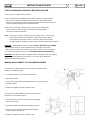
EXPLOSION-PROOF/DUST IGNITION-PROOF AIR VACUUM CLEANER MODEL
MODÈLE DE L'ASPIRATEUR À AIR ADAPTÉ À L'ASPIRATION DES POUDRES EXPLOSIVES SANS RISQUE D'EXPLOSION
MODELO DE ASPIRADORA DE AIRE A PRUEBA DE EXPLOSIÓN/DEFLAGRACIÓN DEL POLVO
A15EXP
(dry use only) (sólo uso en seco) (utilisation sèche seulement)
INSTRUCTIONS FOR USE
INSTRUCCIONES DE USO
INSTRUCTIONS D'UTILISATION
For Use in Class I: Group D - Class II: Group E, F and G Hazardous Locations
ATEX Zone 1, Zone 2, Zone 21 and Zone 22
Para la utilización en lugares peligrosos de clase I: grupo D - Clase II: grupo E, F y G
ATEX zona 1, zona 2, zona 21 y zona 22
Pour utilisation dans les emplacements dangereux de
Classe I: Groupe D -Classe II: Groupes E, F et G
Zone 1, Zone 2, Zone 21 et Zone 22 ATEX
CAUTION: TO INSURE THE SAFE USE OF THIS VACUUM MACHINE,
OPERATORS MUST READ AND UNDERSTAND THE FOLLOWING
INSTRUCTIONS BEFORE ATTEMPTING TO PLACE THE MACHINE IN SERVICE
ATENCIÓN: PARA GARANTIZAR LA UTILIZACIÓN SEGURA DE ESTE ASPIRADOR,
LOS OPERADORES DEBEN LEER Y COMPRENDER LAS SIGUIENTES
INSTRUCCIONES ANTES DE INTENTAR PONER LA MÁQUINA EN MARCHA
MISE EN GARDE: AFIN D'ASSURER UNE UTILISATION SECURITAIRE DE CET
ASPIRATEUR, LES OPERATEURS DOIVENT LIRE ET COMPRENDRE LES
INSTRUCTIONS QUI SUIVENT AVANT LA MISE EN MARCHE DE CETTE MACHINE
C326
01/2011
Nilfisk Industrial Vacuums, 740 Hemlock Lane, Suite 100, Morgantown, PA 19543, (610) 913-5300
INSTRUCTIONS FOR USE
English
PAGE 1
INSTRUCTIONS FOR USE
Contents
Table of contents ………………………………………………………………………………………
Test For Ground Continuity …………………………………………………………………………
Making Adjustments to Container Gaskets ………………………………………………………
Using the Vacuum……………………………………………………………………………………….
Using the Vacuum/ Starting and stopping……………………………………………………………
Using the Vacuum/ Cleaning the Main Filter………………………………………………………….
Using the Vacuum/ Emptying the Container………………………………………………………….
Replacing Parts …………………………………………………………………………………………
Replacing Parts/ Replacing Main filter ………………………………………………………………
Replacing Parts/ Replacing the optional (upstream) Hepa Filter …………………………………
Parts Explosion …………………………………………………………………………………………
Parts Explosion/ Container unit ………………………………………………………………………..
Parts Explosion/ Venturi power-head ………………………………………………………………..
Dimensions ……………………………………………………………………………………………….
Applications ……………………………………………………………………………………………..
Grounding Instructions ……………………………………………………………………………….
Tools and Attachments ……………………………………………………………………………….
Warranty …………………………………………………………………………………………………
PAGE 2
Page
2
3
3
4
5
5
5
6
6
7
8
8
9
10
11
11
11
12
INSTRUCTIONS FOR USE
TEST FOR GROUND CONTINUITY BEFORE EACH USE
Test for ground continuity before each use:
a)The compressed airline supplied with the A15EXP machine is impregnated with
carbon for the purpose of transferring static charge to an earth ground source.
Check to insure that there is electrical conductivity between the body of the vacuum
and the hose fitting attached to the compressed airline.
b) Connect the conductive, collection hose to the inlet of the stainless steel
tank and check to insure that there is electrical conductivity between
end of the hose and the tank inlet.
NOTE: This vacuum must be connected to an earth ground source. If the vacuum
cleaner should malfunction or break down, grounding provides a path of
least resistance for electrical current to reduce the risk of electrical shock.
For added safety, an auxiliary grounding clamp has been included with the machine.
WARNING: If unacceptable results are recorded, DO NOT OPERATE THE CLEANER.
Using the tester, check for continuity between each connection of the vacuum
cleaner (example: tool to wand, wand to hose, hose to machine, etc) If the problem
can not be corrected refer the unit to an AUTHORIZED SERVICE CENTER ONLY.
WARNING: Insure that the conductive, polyester filter assembly (#25, #26, #27, page 9)
is properly mounted inside the recovery tank. If not, refer to the instructions for
“Replacing the Main Filter” (page 6).
MAKING ADJUSTMENTS TO CONTAINER GASKETS
If you suspect the gasket between the Venturi power-head and the filter
chamber is not sealing properly:
1. Loosen latch screws "A" and slide latch downward.
2. Tighten latch screws.
3. Turn on the unit and inspect the seal between the Venturi power-head
and filter chamber.
4. Replace the gasket if the seal continues to leak.
If you suspect the gasket between the filter chamber and the
collection can is not sealing properly:
1. Loosen the screws "A" that lock filter chamber "B" against
the vacuum structure.
2. Lower filter chamber "B" slightly and retighten screws "A".
3. Turn on the unit and inspect the seal between the filter
chamber and the collection can.
4. Replace the gasket if the seal continues to leak.
PAGE 3
INSTRUCTIONS FOR USE
PAGE 4
USING THE VACUUM
CAUTION: OPERATORS SHOULD TEST THE VACUUM MACHINE .
FOR GROUND CONTINUITY BEFORE EACH USE
WARNING: A HEPA FILTER MUST BE INSTALLED IN THE VACUUM MACHINE
WHILE WORKING WITH HAZARDOUS MATERIAL.
FAILURE TO DO SO WILL EXPOSE PEOPLE IN THE WORK
AREA AND OTHERS TO HAZARDOUS MATERIALS WHICH
IS A SERIOUS HEALTH RISK.
EMPTYING: IF THIS VACUUM CLEANER IS USED TO COLLECT HAZARDOUS
MATERIALS, DO NOT ATTEMPT TO OPEN OR EMPTY ITS CONTENTS
WITHOUT PERSONAL PROTECTIVE CLOTHING AND RESPIRATORY
PROTECTION. ALL DISPOSED FILTERS, BAGS, DEBRIS SHOULD
BE TREATED AS A HAZARDOUS SUBSTANCE AND MUST BE
DISPOSED OF IN ACCORDANCE WITH ALL FEDERAL, STATE
AND LOCAL REGULATIONS.
WARNING: THIS EQUIPMENT IS INTENDED FOR EXPLOSION-PROOF/DUST-IGNITION PROOF
OPERATION,ONLY IF USED WITH SUPPLIED OR RECOMMENDED
HOSE AND TOOLS. ANY ALTERATION TO THIS EQUIPMENT BY
A THIRD PARTY WILL NULLIFY ITS WARRANTY.
INSTRUCTIONS FOR USE
PAGE 5
USING THE VACUUM:STARTING AND STOPPING
C
B
1.Fit the accessories on suction inlet "A".
2.Connect the machine to the air main.
3.Start and stop the Vacuum Cleaner by turning the lock valves "B".
4.The pressure governor "C" is used to regulate the suction capacity
CLEANING THE MAIN FILTER
If the performance of the vacuum cleaner decreases during
use, it may be necessary to clean the primary filter:
1. Turn off the vacuum and disconnect the vacuum from
its power source.
2
2. Actuate the filter shaker "A" (Figure 2) by raising
and lowering the lever.
3. Repeat this several times to shake the dirt from the
primary filter.
4. Wait a few minutes for the dust to settle at the bottom
of the container.
5. Empty the container
EMPTYING THE CONTAINER
3
1. Turn off the vacuum and disconnect the
vacuum from its power source.
2. Detach container "A" (Figure 3) by lifting
the handle.
3. Slide the container out from the machine
and carry the container by the handle (figure 4).
4
INSTRUCTIONS FOR USE
PAGE 6
REPLACING THE MAIN FILTER
3
1. Release the latches "A" and remove the Venturi power-head "B" (Figure 3).
2. Raise one side of the filter and reach down under the filter
with one hand to remove split pin "D". This will release
the filter shaker lever "E" from the filter ring "F" (Figure 5).
3
3. Lift up of the filter and cut the ties (G) that attach the filter
to the ring "F"(Figure 5).
4. Unscrew clamp "H" and remove the upper ring "I" (Figure 4).
5. Mount the upper ring "I" onto the new filter and secure
the ring in place with clamp "H" (Figure 4).
4
6. Secure the Filter "C" to the ring "F" using the ties "G"
supplied in the new filter kit (Figure 5).
7. Place the new filter assembly inside the filter chamber and
reconnect the assembly using the split pin "D" (Figure 5).
8. Mount the suction unit "B" onto the machine and secure
in place with the latches "A" (Figure 3).
9. Dispose of the old filter in accordance with all federal,
state and local regulations.
5
INSTRUCTION FOR USE
PAGE 7
REPLACING PARTS
REPLACING THE OPTIONAL (UPSTREAM) HEPA FILTER
1. Release the latches and remove the Venturi power-head
1
2. Separate disc "A" from gasket "B" and remove
disc/filter assembly from the vacuum machine.
2
3. Loosen nut "C" and remove the HEPA filter "D".
3
4. Fit a new HEPA Filter onto Disc"A" and tighten
in place.
4
5. Slide the disc with new filter into gasket "B".
6. Replace the suction unit onto the vacuum machine.
7. Dispose of the old filter in accordance with all
federal, state and local regulations.
POS.
N^CODE
Q
1
8 33323G
1
DISC
DESCRIPTION
POS.
3
2
8 17262
1
HEPA FILTER
4
N^CODE
BR010X
BN10X
Q
DESCRIPTION
1
WASHER
1
NUT
INSTRUCTION FOR USE
PAGE 8
PARTS EXPLOSION
CONTAINER UNIT
POS.
N^CODE
Q
POS.
N^CODE
Q
1
8 36359
1
CAR
DESCRIPTION
29
BR00824X
4
WASHER
DESCRIPTION
1
4083600658
1
CAR, 50 L
30
BRODO8X
4
WASHER
2
8 40261
2
WHEEL
4
WASHER
3
8 40910
2
WHEEL
31
32
BROO8X
BDNO8X
4
NUT
4
BSEE15G
2
CLIP
33
8 32332
1
FILLER
5
6
BRO15ZB
1
WASHER
34
8 32171
1
PUSH-BOTTON
8 38059
4
RIVET
35
8 13010
1
SPRING
7
BVTBCE0840ZB
2
SCREW
36
8 38021
2
PIN
8
BRO08ZB
2
WASHER
37
8 17005
1
SEAL
9
BDABO8ZB
2
NUT
38
8 32314
1
DEFLECTOR
10
BVTEO62OZB
4
SCREW
39
BDNO5X
4
NUT
11
BROO618ZB
4
WASHER
40
BVTBCEO525X
4
SCREW
12
BVTBCEO816X
4
SCREW
41
8 18970
2
BRACHET
13
8 17226
1
SILICON SEAL
42
8 40402
3
WHEEL
14
8 11110
1
CHAMBER
43
BVTBCEO82OX
3
SCREW
15
BVTEZO6O8X
4
SCREW
44
BR00832X
3
WASHER
16
8 18010
2
PLAQUE
45
BROO8ZB
3
WASHER
17
8 36030
2
LOCK
46
BDAO8ZB
3
NUT
18
8 40393
1
BELLOWS
47
8 30337
1
CONTAINER, 25 L
19
8 33221
1
ROD
47
4083000575
1
CONTAINER, 50 L
20
8 40373
1
HANDGRIP
48
8 14579
2
PIN
21
8 38018
1
COTTER PIN
49
BDAO8X
2
NUT
22
BVTBCO616X
1
SCREW
50
8 18971
1
HANDLE
23
BVSTCECO4O6X
1
DOWEL
51
BR00832X
2
WASHER
24
BDAO6X
1
NUT
52
BROO8X
2
WASHER
25
8 33174
1
RING
53
BDNO8X
2
NUT
26
8 15130
1
SUPPORT
54
4083901363
1
GROUND CABLE
27
8 38047
1
ARTICULATION
28
8 15131
1
BELOWS HOLDER
INSTRUCTION FOR USE
PAGE 9
PARTS EXPLOSION
VENTURI POWER-HEAD
POS.
N^CODE
Q
POS.
N^CODE
Q
1
8 16345
1
CAP
22
8 40267
1
CONNECTION
6
SCREW
23
8 40834
1
FITTING
2
BVTBCB0610X
DESCRIPTION
DESCRIPTION
3
BRO06X
6
WASHER
24
8 24164
1
TUBE
4,5,6
8 17692
1
SOUNDPROOFING KIT
25
8 15009
1
RING
7
8
8 16340
1
SEPARATOR
26
8 18078
1
STOP
8 17124
1
SEAL
27
8 17140
1
FILTER
9
8 14270
6
SPACER
28
8 40053
1
TIE
10
BVSTCEC0625X
1
SCREW
29
8 17125
1
SEAL
11
8 16346
1
BODY
30
8 40097
1
PRESSURE GOVERNOR
12
8 14623
3
STUD
31
8 40834
1
CONNECTION
13
8 12384
1
CAP
32
8 40269
2
REDUCTION 1/2 "
14
8 47113
3
RING NUT
33
8 18986
1
BRACKET
15
8 47114
2
SEAL
34
58 18487
1
TIE ROD
16
8 47126
1
CONNECTION
35
8 40933
1
CLAMP
17
8 40838
1
TIE
36
8 40933
1
QUICK CONNECTION
18
8 47099
1
VENTURI
37
8 0556300
1
HEPA FILTER
19
8 47117
2
CONNECTION
38
8 17818
1
SEAL
20
8 24163
6,3"
TUBE
39
8 33340
1
SUPPORT
21
58 47115
3
SEAL
40
8 17056
1
SEAL
INSTRUCTION FOR USE
DIMENSIONS
51'
25L container vacuum cleaner
50L container vacuum cleaner
PAGE 10
INSTRUCTION FOR USE
PAGE 11
APPLICATIONS
The Nilfisk Explosion-Proof/Dust-Ignition Proof vacuum cleaner model A15EXP is ATEX approved for use in Zone 1, Zone 2,
Zone 21 and Zone 22 locations and meets the requirments for use in:
Class l/Group D
Atmospheres containing: gasoline, petroleum, naphtha, benzine, butalie, propane, alcohol,
acetone, benzol, lacquer solvent vapors or natural gas.
Warning: Do not use this or any other Nilfisk CFM vacuum for the purposes of cleaning or extracting fuel residues from
airplanes or ships.
Class II/Group E
Class ll/Group F
Atmospheres containing: metal dust
Atmospheres containing: carbon, black coal or coke dust.
Class ll/Group G
Atmospheres containing: flour, starch or grain dust.
GROUNDING INSTRUCTIONS
This vacuum must be connected to an earth ground source. If the vacuum cleaner should malfunction or break down,
grounding provides a path of least resistance for electrical current to reduce the risk of electrical shock. For added safety,
an auxiliary grounding clamp has been included with the machine.
TOOLS AND ATTACHMENTS
WARNING: This equipment is only intended for explosion-proof/dust-ignition proof operation if it is equipped with the proper
conductive hose and tools. Any alteration to this equipment by a third party will nullify its warranty.
INSTRUCTION FOR USE
PAGE 12
WARRANTY
Nilfisk warrants that its equipment will be free of defects in workmanship or material for a period of two years from the
date of delivery. If the vacuum fails to meet these warranty standards , Nilfisk shall, upon notification within such time
period, correct such non-conformity, at its option, either by repairing any defective part or parts, or by replacing a part
or parts provided that the equipment is returned to an authorized Nilfisk service facility. In all cases freight both ways
will be at expense of the customer. Equipment shall not be returned without advance notice to, and consent of Nilfisk.
EXCEPT AS SPECIFICALLY SET FORTH HEREIN, NILFISK MAKES NO WARRANTIES, EITHER
EXPRESSED OR IMPLIED, AS TO ANY MATTER WHATSOEVER, INCLUDING W1THOUT LIMITATION ANY
AND ALL WARRANTIES OF MERCHANTABILITY, FITNESS OF PURPOSE, OR OTHER WARRANTIES,
ALL OF WHICH ARE EXPRESSLY DISCLAIMED AND EXCLUDED. NEITHER PARTY SHALL BE LIABLE TO THE
OTHER FOR SPECIAL, INDIRECT, INCIDENTAL OR CONSEQUENTIAL DAMAGES, INCLUDING BUT NOT
LIMITED TO LOSS OF PRODUCTION, LOSS OF PROFITS OR ANY OTHER SIMILAR INDIRECT LOSSES
WHICH MIGHT OCCUR AS A RESULT OF DEFECTS, PARTIAL OR TOTAL FAILURE OF THE PRODUCT TO
PERFORM AS SPECIFIED.
Correction of non-conformities or defects in the manner and for the period of time provided above, shall constitute
fulfilment of all Inabilities of Nilfisk to the customer, whether based on contract, negligence or otherwise with
respect to, or arising out of such equipment. The remedies set forth herein are exclusive, and the inability of Niifisk
with respect to this sale or anything done in connection therewith, whether in contract, in tort, under any warranty,
or otherwise, shall not, except as expressly provided herein, exceed the price of the equipment or part on which such
liability is based.
This warranty does not cover repairs due to normal wear and tear, accident, neglect, misuse or abuse, incorrect
installation or use other than as described in the instruction booklet. Breaks in hoses and cables are not covered.
This warranty Is rendered void if the motor number plate is removed or defaced or if repairs are made or attempted
by persons not authorized by Nilflsk.
Some states do not allow exclusion of implied warranties or limitations on how Long an implied warranty lasts so the
above exclusions or limitation of implied warranties may not apply. Some states do not allow exclusion or limitation
of incidental or consequential damages so the above exclusion or limitation of incidental or consequential damages
may not apply. Limited warranties set forth above give specific legal rights. Customer may have other rights which
vary from state to state.
DISCLAIMER
The purchaser and intended user of this Nilfisk EXP vacuum acknowledge that their Authority Having Jurisdiction (AHJ) as
defined in Article 100 of the National Electric Code (NEC – NFPA 70) has determined this specific type of vacuum equipment is
suitable for use in the intended applications and hazloc rated environments. Nilfisk-Advance, the product manufacturer, is not
an AHJ and cannot approve any particular EXP vacuum product for any specific application or use. It is the purchaser‟s and the
intended user‟s responsibility to ensure that the vacuum is used properly as described in the instruction manual and in
accordance with the AHJ‟s approval. By issuing a purchase order, the purchaser and intended user acknowledge
understanding the role of their AHJ along with the capabilities and limitations of the vacuum equipment. If you require
assistance in identifying your AHJ, please contact your local Nilfisk District Manager for assistance.
Nilfisk Industrial Vacuums, 740 Hemlock Lane, Suite 100, Morgantown, PA 19543, (610) 913-5300
INSTRUCCIONES DE USO
Español
PÁGINA 1
INSTRUCCIONES DE USO
Contenido
PÁGINA 2
Página
Índice ………………………………………………………………………………………................2
Prueba de continuidad de tierra ………………………………………………………………….3
Realización de ajustes en las juntas del contenedor ………………………………………….
3
Utilización de la aspiradora………………………………………………………………………….
4
Utilización de la aspiradora/ Arranque y parada……………………………………………………
5
Utilización de la aspiradora/ Limpieza del filtro principal………………………………………….
5
Utilización de la aspiradora/ Vaciado del contenedor……………………………………………5
Sustitución de piezas …………………………………………………………………………….. 6
Sustitución de piezas/ Sustitución del filtro principal ……………………………………………
6
Sustitución de piezas/ Sustitución del filtro (de succión) Hepa opcional ……………………7
Explosión de piezas …………………………………………………………………………………8
Explosión de piezas/ Unidad del contenedor ………………………………………………………
8
Explosión de piezas/ Cabeza de potencia Venturi ………………………………………………9
Dimensiones ……………………………………………………………………………………………
10
Aplicaciones ……………………………………………………………………………………………
11
Instrucciones de puesta a tierra ……………………………………………………………………
11
Herramientas y accesorios ……………………………………………………………………………
11
Garantía …………………………………………………………………………………………………
12
INSTRUCCIONES DE USO
PRUEBA DE CONTINUIDAD DE TIERRA ANTES DE CADA USO
Prueba de continuidad de tierra antes de cada uso:
a)La línea de aire comprimido de la máquina A15EXP está impregnada con carbón para
transmitir la carga estática a tierra . Compruebe que hay conexión eléctrica entre el
aspirador y la manguera ajustada a la línea de aire comprimido.
b)Conecte el conducto de la manguera al enchufe del depósito de acero inoxidable para
asegurar que hay conexión eléctrica entre el final de la manguera y el enchufe del
NOTA: el aspirador debe estar conectado a tierra Si el aspirador no funciona
correctamente o se estropea, la conexión a tierra proporciona una corriente
de menos resistencia para reducir el riesgo de shock eléctrico.
ATENCIÓN: Si se registran resultados inaceptables, NO PONGA EN FUNCIONAMIENTO LA ASPIRADORA.
Utilizando el comprobador, compruebe la continuidad entre cada conexión de la aspiradora
(ejemplo: herramienta a lector, lector a tubo, tubo a máquina, etc.) Si el problema
no puede corregirse envíe la unidad a un CENTRO DE SERVICIO AUTORIZADO EXCLUSIVAMENTE.
ATENCIÓN: Asegúrese de que el conjunto del filtro de poliéster, conductivo (#25, #26, #27, page 9), está correctamente
montado en el tanque de recuperación. De no ser así, consulte las instrucciones para
Sustitución del filtro principal (página 6).
REALIZACIÓN DE AJUSTES EN LAS JUNTAS DEL CONTENEDOR
Si sospecha que la junta entre la cabeza de potencia Venturi y la cámara
de filtrado no sella correctamente:
1. Afloje los tornillos de retención "A" y deslice el pasador hacia abajo.
2. Apriete los tornillos de retención.
3. Gire la unidad y compruebe el sello entre la cabeza de potencia
Venturi y la cámara de filtrado.
4. Sustituya la junta si continúa la fuga en el sello.
Si sospecha que la junta entre la cámara de filtrado y el
depósito de recogida no sella correctamente:
1. Afloje los tornillos "A" que bloquean la cámara de filtrado "B"
contra la estructura de la aspiradora.
2. Baje la cámara de filtrado ligeramente y reapriete los
tornillos "A".
3. Gire la unidad y compruebe el sello entre la cámara de
filtrado y el depósito de recogida.
4. Sustituya la junta si continúa la fuga en el sello.
PÁGINA 3
INSTRUCCIONES DE USO
PÁGINA 4
UTILIZACIÓN DE LA ASPIRADORA
PRECAUCIÓN: LOS OPERADORES DEBERÍAN PROBAR LA CONTINUIDAD DE TIERRA
DE LA ASPIRADORA ANTES DE CADA USO
ATENCIÓN: DEBE EXISTIR UN FILTRO HEPA INSTALADO EN LA ASPIRADORA
MIENTRAS SE TRABAJA CON MATERIAL PELIGROSO.
DE NO HACERLO SE EXPONDRÁ A LAS PERSONAS EN EL ÁREA DE
TRABAJO Y OTRAS ÁREAS A MATERIALES PELIGROSOS QUE
REPRESENTAN UN RIESGO SERIO PARA LA SALUD.
VACIADO: SI ESTA ASPIRADORA SE UTILIZA PARA RECOGER MATERIALES
PELIGROSOS, NO INTENTE ABRIR O VACIAR SU CONTENIDO
SIN ROPA DE PROTECCIÓN PERSONAL Y PROTECCIÓN
RESPIRATORIA. TODOS LOS FILTROS, BOLSAS, DESHECHOS
ELIMINADOS DEBERÍAN TRATARSE COMO SUSTANCIAS PELIGROSAS
Y DEBEN ELIMINARSE DE ACUERDO CON LAS NORMAS FEDERALES,
ESTATALES Y LOCALES.
ATENCIÓN: ESTE EQUIPO ESTÁ CONCEBIDO PARA UN FUNCIONAMIENTO
A PRUEBA DE EXPLOSIÓN/DEFLAGRACIÓN DEL POLVO SÓLO SI SE
UTILIZA CON EL TUBO Y LAS HERRAMIENTAS SUMINISTRADAS O
RECOMENDADAS. LAS ALTERACIONES DE ESTE EQUIPO POR PARTE
DE UN TERCERO ANULARÁN SU GARANTÍA.
INSTRUCCIONES DE USO
PÁGINA 5
UTILIZACIÓN DE LA ASPIRADORA: ARRANQUE Y PARADA
C
B
1.Coloque los accesorios en la toma de admisión de succión "A".
2.Conecte la máquina a la canalización de aire comprimido.
3.Arranque y detenga la aspiradora girando las válvulas de bloqueo "B".
4.El regulador de presión "C" se utiliza para regular la capacidad de succión.
LIMPIEZA DEL FILTRO PRINCIPAL
Si el rendimiento de la aspiradora disminuye durante
su uso, puede que se necesite limpiar el filtro principal:
1. Apague la aspiradora y desconecte la aspiradora de
su fuente de alimentación de corriente.
2. Active el agitador del filtro "A" (ilustración 2) subiendo
y bajando la palanca.
3. Repita este paso varias veces para agitar la suciedad del
filtro principal.
4. Espere unos pocos minutos para que el polvo se deposite en
el fondo del contenedor.
5. Vacíe el contenedor
VACIADO DEL CONTENEDOR
1. Apague la aspiradora y desconecte la aspiradora
de su fuente de alimentación de corriente.
2. Suelte el contenedor "A" (ilustración 3)
subiendo la palanca.
3. Desplace el contenedor fuera de la máquina
y traslade el contenedor por el mango
(ilustración 4).
3
2
4
INSTRUCCIONES DE USO
PÁGINA 6
SUSTITUCIÓN DEL FILTRO PRINCIPAL
1. Libere los pasadores "A" y extraiga la cabeza de potencia Venturi "B" (ilustración 3).
2. Eleve un lado del filtro e introduzca la mano por debajo del filtro
para extraer el pasador de aletas "D". Esto liberará
3
la palanca del agitador del filtro "E" del anillo del filtro "F" (ilustración 5).
3. Eleve el filtro y corte las conexiones (G) que unen el filtro
con el anillo "F" (ilustración 5).
4. Destornille la abrazadera "H" y extraiga el anillo superior "I" (ilustración 4).
5. Monte el anillo superior "I" en el nuevo filtro y fije
4
el anillo en su posición con la abrazadera "H" (ilustración 4).
6. Fije el filtro "C" en el canillo "F" utilizando las conexiones "G"
suministradas en el nuevo kit de filtros (ilustración 5).
7. Coloque el nuevo conjunto de filtros en la cámara de filtrado y
reconecte el conjunto utilizando el pasador de aletas "D" (ilustración 5).
8. Monte la unidad de succión "B" en la máquina y fíjela en su
posición con los pasadores "A" (ilustración 3).
9. Elimine el filtro antiguo de acuerdo con todas las normas federales,
estatales y locales.
5
INSTRUCCIONES DE USO
PÁGINA 7
SUSTITUCIÓN DE PIEZAS
SUSTITUCIÓN DEL FILTRO (DE SUCCIÓN) HEPA OPCIONAL
1. Suelte los pasadores y extraiga la cabeza de potencia Venturi
2. Separe el disco "A" de la junta "B" y extraiga
el conjunto de discos/filtros de la aspiradora.
1
3. Afloje la tuerca "C" y extraiga el filtro HEPA "D".
2
4. Coloque un nuevo filtro HEPA en el disco "A" y fíjelo
en su posición.
3
4
5. Deslice el disco con un nuevo filtro en la junta "B".
6. Sustituya la unidad de succión en la aspiradora.
7. Elimine el filtro antiguo de acuerdo con todas las normas federales,
estatales y locales.
POS.
N^CODE
Q
1
8 33323
1
DISCO
DESCRIPCIÓN
POS.
3
2
8 17262
1
FILTRO HEPA
4
N^CODE
BR010X
BN10X
Q
DESCRIPCIÓN
1
ARANDELA
1
TUERCA
INSTRUCCIONES DE USO
PÁGINA 8
EXPLOSIÓN DE PIEZAS
UNIDAD DEL CONTENEDOR
POS.
N^CODE
Q
POS.
N^CODE
Q
1
8 36359
1
CARRO
DESCRIPCIÓN
29
BR00824X
4
ARANDELA
DESCRIPCIÓN
1
4083600658
1
CARRO, 50 L
30
BRODO8X
4
ARANDELA
2
8 40261
2
RUEDA
BROO8X
4
ARANDELA
3
8 40910
2
RUEDA
31
32
BDNO8X
4
TUERCA
4
BSEE15G
2
ANILLO DE RETENCIÓN
33
8 32332
1
RELLENO
5
6
BRO15ZB
1
ARANDELA
34
8 32171
1
PULSADOR
8 38059
4
REMACHE
35
8 13010
1
RESORTE
7
BVTBCE0840ZB
2
TORNILLO
36
8 38021
2
CLAVIJA
8
BRO08ZB
2
ARANDELA
37
8 17005
1
SELLO
9
BDABO8ZB
2
TUERCA
38
8 32314
1
DEFLECTOR
10
BVTEO62OZB
4
TORNILLO
39
BDNO5X
4
TUERCA
11
BROO618ZB
4
ARANDELA
40
BVTBCEO525X
4
TORNILLO
12
BVTBCEO816X
4
TORNILLO
41
8 18970
2
REMACHE
13
8 17226
1
SELLO DE SILICONA
42
8 40402
3
RUEDA
14
8 11110
1
CÁMARA
43
BVTBCEO82OX
3
TORNILLO
15
BVTEZO6O8X
4
TORNILLO
44
BR00832X
3
ARANDELA
16
8 18010
2
PLACA
45
BROO8ZB
3
ARANDELA
17
8 36030
2
BLOQUEO
46
BDAO8ZB
3
TUERCA
18
8 40393
1
FUELLE
47
8 30337
1
CONTENEDOR
19
8 33221
1
VARILLA
47
4083000575
1
CONTENEDOR, 50 L
20
8 40373
1
MANGO
48
8 14579
2
CLAVIJA
21
8 38018
1
CHAVETA DE RETÉN
49
BDAO8X
2
TUERCA
22
BVTBCO616X
1
TORNILLO
50
8 18971
1
MANIVELA
23
BVSTCECO4O6X
1
ESPIGA
51
BR00832X
2
ARANDELA
24
BDAO6X
1
TUERCA
52
BROO8X
2
ARANDELA
25
8 33174
1
ANILLO
53
BDNO8X
2
TUERCA
26
8 15130
1
SOPORTE
54
4083901363
1
CABLE A TIERRA
27
8 38047
1
ARTICULACIÓN
28
8 15131
1
SOPORTE DE FUELLE
INSTRUCCIONES DE USO
PÁGINA 9
EXPLOSIÓN DE PIEZAS
CABEZA DE POTENCIA VENTURI
POS.
N^CODE
Q
POS.
N^CODE
Q
1
8 16345
1
TAPA
22
8 40267
1
CONEXIÓN
2
BVTBCB0610X
DESCRIPCIÓN
DESCRIPCIÓN
6
TORNILLO
23
8 40834
1
ADAPTADOR
3
BRO06X
6
ARANDELA
24
8 24164
1
TUBO
4,5,6
8 17692
1
KIT DE INSONORIZACIÓN
25
8 15009
1
ANILLO
7
8
8 16340
1
SEPARADOR
26
8 18078
1
PARADA
8 17124
1
SELLO
27
8 17140
1
FILTRO
9
8 14270
6
ESPACIADOR
28
8 40053
1
CONEXIÓN
10
BVSTCEC0625X
1
TORNILLO
29
8 17125
1
SELLO
11
8 16346
1
CUERPO
30
8 40097
1
REGULADOR DE PRESIÓN
12
8 14623
3
PRISIONERO DE FIJACIÓN
31
8 40834
1
CONEXIÓN
13
8 12384
1
TAPA
32
8 40269
2
REDUCCIÓN 1/2 "
14
8 47113
3
TUERCA CON ANILLO
33
8 18986
1
ABRAZADERA
15
8 47114
2
SELLO
34
58 18487
1
VARILLA DE CONEXIÓN
16
8 47126
1
CONEXIÓN
35
58 18472
1
GRAPA
17
8 40838
1
CONEXIÓN
36
8 40933
1
CONEXIÓN RÁPIDA
18
8 47099
1
VENTURI
37
8 0556300
1
HEPA FILTRO
19
8 47117
2
CONEXIÓN
38
8 17818
1
SELLO
20
8 24163
6,3"
TUBO
39
8 33340
1
APOYO
21
58 47115
3
SELLO
40
8 17056
1
SELLO
INSTRUCCIONES DE USO
DIMENSIONES
51'
Máquina con 25 L de contenedor
Máquina con 50 L de contenedor
PÁGINA 10
INSTRUCCIONES DE USO
PÁGINA 11
APLICACIONES
La aspiradora a prueba de explosión/deflagración del polvo Nilfisk modelo A15EXP tiene aprobación ATEX para el uso
en la zona 1, zona 2, zona 21 y zona 22 y satisface las especificaciones para el uso en:
Clase I/grupo D
Atmósferas con contenido de: gasolina, petróleo, nafta, bencina, butano, propano, alcohol,
acetona, benzol, vapores disolventes de barniz o gas natural.
Atención: no utilizar este o otros aspiradores Nilfisk-CFM para limpiar o sacar residuos de combustible de avión o naves
Clase II/grupo E
Atmósferas que contienen: polvo de metal
Clase II/grupo F
Atmósferas con contenido de: carbono, carbón negro o coque pulverizado.
Clase II/grupo G
Atmósferas con contenido de: harina, almidón o grano en polvo.
INSTRUCCIONES DE PUESTA A TIERRA
El aspirador debe estar conectado a tierra Si el aspirador no funciona correctamente o se estropea, la conexión a tierra
proporciona una corriente de menos resistencia para reducir el riesgo de shock eléctrico. Para más seguridad, una pinza
auxiliar se ha incluido a la máquina.
HERRAMIENTAS Y ACCESORIOS
ATENCIÓN: Este equipo está concebido únicamente para un funcionamiento a prueba de explosión/deflagración
del polvo si está equipado con el tubo conductivo y las herramientas adecuadas.
Las alteraciones de este equipo por parte de un tercero anularán su garantía.
INSTRUCCIONES DE USO
PÁGINA 12
GARANTÍA
Nilfisk garantiza que este equipo estará libre de defectos de mano de obra o materiales durante un periodo de dos años
fecha de entrega. Si la aspiradora no cumple estas normas de garantía, Nilfisk, con notificación dentro de dicho plazo,
desde la corregirá dicha disconformidad, a discreción propia, bien reparando cualquier pieza o piezas defectuosas
o sustituyendo una pieza o piezas siempre que el equipo se devuelva a una centro de servicio autorizado de Nilfisk.
En todos los casos, el transporte en ambos sentidos correrá por cuenta del cliente. El equipo no se devolverá sin
notificación previa a Nilfisk, ni sin su consentimiento.
SALVO LO AQUÍ INDICADO DE FORMA EXPRESA, NILFISK NO PRESTA NINGUNA GARANTÍA EXPLÍCITA
CON RELACIÓN A CUALQUIER PROBLEMA, INCLUIDA, PERO NO DE FORMA EXCLUSIVA, CUALQUIER
NI IMPLÍCITAMENTE GARANTÍA DE COMERCIABILIDAD, IDONEIDAD PARA UNA FINALIDAD U OTRAS GARANTÍAS,
RECHAZÁNDOSE Y EXCLUYÉNDOSE EXPRESAMENTE TODAS ELLAS. NINGUNA PARTE SERÁ RESPONSABLE
RESPECTO A LA OTRA POR DAÑOS ESPECIALES, INDIRECTOS, INCIDENTALES O CONSECUENCIALES,
INCLUIDOS, PERO NO EXCLUSIVAMENTE LA PÉRDIDA DE PRODUCCIÓN, LA PÉRDIDA DE BENEFICIOS O
CUALQUIER OTRO DAÑO INDIRECTO SIMILAR QUE SUCEDA COMO RESULTADO DE DEFECTOS, UN FALLO
PARCIAL O TOTAL DEL PRODUCTO PARA RENDIR SEGÚN LO ESPECIFICADO.
La corrección de las disconformidades del modo y durante el periodo indicados anteriormente constituirá
el cumplimiento de todas las responsabilidades de Nilfisk respecto al cliente, bien sean contractuales, por negligencia
o de otro modo con relación al equipo o que se produzcan por causas ajenas al equipo. Los remedios expuestos aquí
son exclusivos, y la responsabilidad de Nilfisk con relación a esta venta o cualquier acto realizado respecto a los mismos,
ya sea contractual, extracontractual o bajo cualquier garantía, o de otro modo no excederán, salvo lo expresamente
indicado aquí, el precio del equipo o la parte del mismo en la que se base la responsabilidad.
Esta garantía no cubre reparaciones debidas al desgaste normal, accidentes, negligencia, uso inapropiado o abuso,
instalación incorrecta o uso distinto al descrito en el manual de instrucciones. Las roturas en tubos y cables no
están cubiertas. Esta garantía será nula si la placa identificadora del motor se quita o se desfigura o si se realizan
o se intentan realizar reparaciones por personas no autorizadas por Nilflsk.
Algunos estados no permiten la exclusión de garantías implícitas o limitaciones sobre cuánto dura la garantía implícita,
de modo que las anteriores exclusiones o la limitación de garantías implícitas puede no ser de aplicación. Algunos
estados no permiten la exclusión o la limitación de daños incidentales o consecuenciales, de modo que la exclusión
o la limitación de daños incidentales o consecuenciales puede no ser de aplicación. Las garantías limitadas indicadas
anteriormente conceden derechos legales específicos. Los clientes pueden tener otros derechos que varían
de estado a estado.
RENUNCIA
Tanto el comprador como el usuario final de la aspiradora Nilfisk EXP reconocen que su autoridad competente (AHJ por sus siglas en inglés), tal
como lo establece el artículo 100 del Código Eléctrico Nacional ( National Electric Code - NEC – NFPA 70), ha determinado que este tipo específico
de aspiradora es adecuada para su uso en aquellas aplicaciones previstas y en ambientes considerados como peligrosos. El fabricante del producto
Nilfisk-Advance no es una autoridad competente y no está facultado para aprobar ningún modelo de aspiradora EXP para cualquiera de sus
aplicaciones y usos. Es responsabilidad del comprador y del usuario final garantizar su uso adecuado de acuerdo al manual de instrucciones y de
conformidad con el permiso de la autoridad competente. Al emitir una orden de compra, tanto el comprador como el usuario final reconocen y
comprenden la función de su autoridad competente así como las posibilidades y limitaciones de la aspiradora. Si necesita asistencia para ubicar a
su autoridad competente, por favor póngase en contacto con su gerente local de Nilfisk.
Nilfisk Industrial Vacuums, 740 Hemlock Lane, Suite 100, Morgantown, PA 19543, (610) 913-5300
INSTRUCTIONS D'UTILISATION
Français
PAGE 1
INSTRUCTIONS D'UTILISATION
PAGE 2
Contenu
Page
Table des matières …………………………………………………………………………………...
Test de continuité pour mise à la terre ………………………………………………………….
Réglages des joints statiques du réservoir ……………………………………………………….
Utilisation de l'aspirateur……………………………………………………………………………..
Utilisation de l'aspirateur/Démarrage et arrêt………………………………………………………
Utilisation de l'aspirateur/Nettoyage du filtre principal………………………………………….…
Utilisation de l'aspirateur/Évacuation du réservoir………………………………………………….
Remplacement de pièces ……………………………………………………………………………
Remplacement de pièces/Remplacement du filtre principal ………………………………………
Remplacement de pièces/ Replacement du filtre Hepa optionnel (aspiration vers le haut) ….
Vue éclatée des pièces …………………………………………………………………………….…
Vue éclatée des pièces/Unité du réservoir…………………………………………………………..
Vue éclatée des pièces/Tête de pompe Venturi ……………………………………………………
Dimensions ……………………………………………………………………………………………….
Applications ……………………………………………………………………………………………..
Instructions pour mise à la terre …………………………………………………………………....
Outils et accessoires …………………………………………………………………………………..
Garantie ………………………………………………………………………………………………..…
2
3
3
4
5
5
5
6
6
7
8
8
9
10
11
11
11
12
INSTRUCTIONS D'UTILISATION
TESTEZ LA CONTINUITÉ DE MISE À LA TERRE AVANT CHAQUE
UTILISATION
Testez la continuité de mise à la terre avant chaque utilisation :
a) Le tuyau de l'air comprimé fourni avec le mod. A15EXP contient du charbon afin
de décharger l'électricité statique à la masse. Il faudra donc contrôler que la
conductivité électrique soit présente entre le corps de l'aspirateur et le
raccord du tuyau attaché à l'air comprimé.
b) Relier le tuyau flexible conductif à l'embout de la cuve en acier
inox et contrôler qu'il y soit la conductivité électrique entre la
fin du flexible et l'embout de la cuve.
NOTES: Cet aspirateur doit être relié à la masse. Si l'aspirateur devait
ne pas fonctionner ou tomber en panne, la mise à terre garantie une
résistance mineure du courant électrique afin de réduire le risque
d'électrocution. Pour une majeure sureté, une fermeture auxiliaire de
mise à terre est fournie avec l'appareil.
MISE EN GARDE : Si des résultats inacceptables sont enregistrés, N'UTILISEZ PAS LE NETTOYEUR.
Utilisez le dispositif de test pour vérifier la présence de continuité entre chaque connexion de l'aspirateur
(exemples : outil vers la lance, lance vers le boyau, boyau vers la machine, etc.). Si le problème ne peut être
résolu, adressez-vous à un CENTRE DE SERVICE AUTORISÉ UNIQUEMENT pour la vérification de l'unité.
MISE EN GARDE : Assurez-vous que le groupe du filtre conductrice de polyester (#25, #26, #27, page 9)
est correctement monté sur le réservoir de récupération. Si ce n'est pas le cas,
consultez les instructions de "Remplacement du Filtre principal" (page 6).
RÉGLAGES DES JOINTS STATIQUES DU RÉSERVOIR
Si vous croyez que le joint statique entre la tête de pompe Venturi et la
chambre du filtre n'est pas correctement scellé :
1. Désserrez les vis de l'attache « A » et laissez l'attache glisser
vers le bas.
2. Serrez les vis de l'attache.
3. Mettez l'unité en marche et vérifiez le joint d'étanchéité entre la tête
de pompe Venturi et la chambre du filtre.
4. Remplacez le joint statique si le joint d'étanchéité continue à fuir.
Si vous croyez que le joint statique entre la chambre du filtre et le
contenant de collection n'est pas correctement scellé:
1. Désserrez les vis « A » qui verrouillent la chambre de filtre
« B » contre la structure de l'aspirateur.
2. Abaissez légèrement la chambre du filtre « B » et resserrez
les vis « A ».
3. Mettez l'unité en marche et vérifiez le joint d'étanchéité entre
la tête la chambre du filtre et le contenant de collection.
4. Remplacez le joint statique si le joint d'étanchéité continue à fuir.
PAGE 3
INSTRUCTIONS D'UTILISATION
PAGE 4
UTILISATION DE L'ASPIRATEUR
AVERTISSEMENT : LES OPÉRATEURS DOIVENT TESTER L'ASPIRATEUR
AVANT CHAQUE UTILISATION POUR ASSURER
LA CONTINUITÉ DE MISE À LA TERRE
MISE EN GARDE : UN FILTRE HEPA DOIT ÊTRE INSTALLÉ DANS L'ASPIRATEUR
LORS DE TRAVAUX AVEC DES MATIÈRES DANGEREUSES.
À DÉFAUT DE SUIVRE CETTE INSTRUCTION LES INDIVIDUS
AINSI QUE D'AUTRES GENS SITUÉS À L'INTÉRIEUR DE LA
ZONE DE TRAVAIL SERONT EXPOSÉS À DES MATIÈRES
DANGEREUSES CE QUI CONSTITUE UN RISQUE GRAVE
POUR LA SANTÉ.
ÉVACUATION :
SI CET ASPIRATEUR EST UTILISÉ POUR COLLECTER DES
MATIÈRES DANGEREUSE, NE TENTEZ PAS D'OUVRIR NI VIDER
SON CONTENU SANS L'UTILISATION DE VÊTEMENT DE
PROTECTION INDIVIDUELLE ET DE PROTECTION RESPIRATOIRE.
TOUS LES FILTRES, SAC ET DÉBRIS USAGÉS DOIVENT ÊTRE
ÉLIMINÉ ET TRAITÉ COMME DES MATIÈRES DANGEREUSES
EN CONFORMITÉ AVEC TOUS LES RÈGLEMENTS FÉDÉRAUX,
PROVINCIAUX ET LOCAUX.
MISE EN GARDE : CET APPAREIL EST ADAPTÉ À L'ASPIRATION DES POUDRES
EXPLOSIVES SANS RISQUE D'EXPLOSION SEULEMENT S'IL
EST UTILISÉ AVEC LE TUYAU ET LES ACCESSOIRES EN
DOTATION OU CONSÉILLÉS. TOUTE MODIFICATION
DU PRODUIT PAR DES TIERS EN ANNULERA LA GARANTIE.
INSTRUCTIONS D'UTILISATION
PAGE 5
UTILISATION DE L'ASPIRATEUR : DÉMARRAGE ET ARRÊT
C
B
1. Placez les accessoires sur l'orifice d'aspiration « A ».
2. Branchez la machine à la conduite d'aération principale.
3. Démarrez et arrêtez l'Aspirateur en tournant les soupapes de verrouillage « B ».
4. Le régulateur de pression « C » est utilisé pour régler la capacité d'aspiration.
NETTOYAGE DU FILTRE PRINCIPAL
Si le rendement de l'aspiration décroît pendant son utilisation
le filtre principal doit probablement être nettoyé :
1. Arrêtez l'aspirateur et débranchez-le de
sa source d'alimentation.
2
2. Actionnez l'agitateur de filtre « A » (Figure 2) en soulevant
et abaissant le lévrier.
3. Répétez à plusieurs reprises pour retirer la saleté du
filtre principal.
4. Attendez quelques minutes pour que la poussière se pose au bas
du réservoir.
5. Videz le réservoir.
ÉVACUATION DU RÉSERVOIR
1. Arrêtez l'aspirateur et débranchez-le de
sa source d'alimentation.
3
2. Détachez le couvercle « A » (Figure 3) en soulevant
la poignée.
3. Glissez le réservoir hors de la machine
et transportez le réservoir en utilisant la poignée
(Figure 4).
4
INSTRUCTIONS D'UTILISATION
PAGE 6
REMPLACEMENT DU FILTRE PRINCIPAL
1. Débloquez les attaches « A » et retirez la tête de pompe Venturi
« B » (Figure 3).
2. Soulevez un côté du filtre et étirez votre bras afin d'atteindre la partie sous le filtre
3
et avec une main, retirez la goupille fendue « D ». Cela débloquera
le levier de l'agitateur du filtre « E. » de l'anneau du filtre « F » (Figure 5).
3. Soulevez du filtre et coupez les traverses (G) qui fixent le filtre
à l'anneau « F » (Figure 5).
4. Dévissez la bride « H » et retirez l'anneau supérieur « I » (Figure 4).
5. Montez l'anneau supérieur « I » sur le nouveau filtre et sécurisez
4
l'anneau en position avec la bride « H » (Figure 4).
6. Sécurisez le filtre « C » à l'anneau « F » en utilisant les traverses « G »
qui sont fournis avec le nouveau kit de filtre (Figure 5).
7. Placez l'assemblage de nouveau filtre à l'intérieur de la chambre du filtre et
rebranchez l'assemblage en utilisant la goupille fendue « D » (Figure 5).
8. Montez l'unité d'aspiration « B » sur la machine et fixez
en position sécuritaire avec les attaches « A » (Figure 3).
9. Éliminez le filtre usagé en conformité avec tous les règlements
fédéraux, provinciaux et locaux.
5
INSTRUCTIONS D'UTILISATION
PAGE 7
REMPLACEMENT DE PIÈCES
REMPLACEMENT DU FILTRE HEPA OPTIONNEL (ASPIRATION VERS LE HAUT)
1. Débloquez les attaches « A » et retirez la tête de pompe Venturi « B ».
1
2. Séparez le disque « A » du joint statique « B » et retirez
l'assemblage du disque/filtre de l'aspirateur.
2
3. Désserrez l'écrou « C » et retirez le filtre HEPA « D ».
3
4. Placez un nouveau filtre HEPA sur le disque « A » et serrez
en position
4
5. Glissez le disque accompagné du nouveau filtre sur le joint statique « B ».
6. Replacez l'unité d'aspiration sur l'aspirateur.
7. Élimenez le filtre usagé en conformité avec tous les règlements
fédéraux, provinciaux et locaux.
POS.
N^CODE
Q
DESCRIPTION
POS.
1
8 33323
1
DISQUE
3
2
8 17262
1
FILTRE HEPA
4
N^CODE
BR010X
BN10X
Q
DESCRIPTION
1
RONDELLE
1
ÉCROU
INSTRUCTIONS D'UTILISATION
PAGE 8
VUE ÉCLATÉE DES PIÈCES
UNITÉ DU RÉSERVOIR
POS.
N^CODE
Q
DESCRIPTION
POS.
N^CODE
Q
1
1
2
3
4
5
6
7
8
9
10
11
12
13
14
15
16
17
18
19
20
21
22
23
24
25
26
27
8 36359
4083600658
8 40261
8 40910
BSEE15G
BRO15ZB
8 38059
BVTBCE0840ZB
BRO08ZB
BDABO8ZB
BVTEO62OZB
BROO618ZB
BVTBCEO816X
8 17226
8 11110
BVTEZO6O8X
8 18010
8 36030
8 40393
8 33221
8 40373
8 38018
BVTBCO616X
BVSTCECO4O6X
BDAO6X
8 33174
8 15130
8 38047
1
1
2
2
2
1
4
2
2
2
4
4
4
0
1
4
2
2
1
1
1
1
1
1
1
1
1
1
CADRE
CAR, 50 L
ROUE
ROUE
ANNEAU ÉLASTIQUE
RONDELLE
RIVET
VIS
RONDELLE
ÉCROU
VIS
RONDELLE
VIS
JOINT EN SILICONE
CHAMBRE
VIS
PLAQUE
VERROU
SOUFFLETS
TIGE
POIGNÉE À MAIN
CLAVETTE
VIS
GOUPILLE
ÉCROU
ANNEAU
SUPPORT
ARTICULATION
29
30
31
32
33
34
35
36
37
38
39
40
41
42
43
44
45
46
47
47
48
49
50
51
52
53
54
BR00824X
BRODO8X
BROO8X
BDNO8X
8 32332
8 32171
8 13010
8 38021
8 17005
8 32314
BDNO5X
BVTBCEO525X
8 18970
8 40402
BVTBCEO82OX
BR00832X
BROO8ZB
BDAO8ZB
8 30337
4083000575
8 14579
BDAO8X
8 18971
BR00832X
BROO8X
BDNO8X
4083901363
4
4
4
4
1
1
1
2
1
1
4
4
2
3
3
3
3
3
1
1
2
2
1
2
2
2
1
28
8 15131
1
SUPPORT DE SOUFFLET
DESCRIPTION
RONDELLE
RONDELLE
RONDELLE
ÉCROU
REMPLISSEUSE
BOUTON PRESSION
RESSORT
GOUPILLE
JOINT D'ÉTANCHIÉTÉ
DÉFLECTEUR
ÉCROU
VIS
SUPPORT
ROUE
VIS
RONDELLE
RONDELLE
ÉCROU
RESERVOIR, 25 L
RESERVOIR, 50 L
GOUPILLE
ÉCROU
POIGNÉE
RONDELLE
RONDELLE
ÉCROU
CABLE DE MISE A TERRE
PAGE 9
INSTRUCTIONS D'UTILISATION
VUE ÉCLATÉE DES PIÈCES
TÊTE DE POMPE VENTURI
POS.
N^CODE
Q
DESCRIPTION
1
8 16345
1 COUVERCLE
2 BVTBCB0610X
6 VIS
3
BRO06X
6 RONDELLE
4,5,6
8 17692
1 KIT D'INSONORISATION
7
8 16340
1 SÉPARATEUR
8
8 17124
1 JOINT D'ÉTANCHÉITÉ
9
8 14270
6 CALE
10 BVSTCEC0625X 1 VIS
11
8 16346
1 CORPS
12
8 14623
3 GOUJON
13
8 12384
1 COUVERCLE
14
8 47113
3 ÉCROU À ŒIL
15
8 47114
2 JOINT D'ÉTANCHÉITÉ
16
8 47126
1 RACCORD
17
8 40838
1 TRAVERSE
18
8 47099
1 VENTURI
19
8 47117
2 RACCORD
20
8 24163
6,3" TUBE
21
58 47115
3 JOINT D'ÉTANCHÉITÉ
POS. N^CODE
22
23
24
25
26
27
28
29
30
31
32
33
34
35
36
37
38
39
40
8 40267
8 40834
8 24164
8 15009
8 18078
8 17140
8 40053
8 17125
8 40097
8 40834
8 40269
8 18986
58 18487
58 18472
8 40933
8 0556300
8 17818
8 33340
8 17056
Q
DESCRIPTION
1 RACCORD
1 PIÈCE DE FIXATION
1 TUBE
1 ANNEAU
1 STOP
1 FILTRE
1 TRAVERSE
1 JOINT D'ÉTANCHÉITÉ
1 RÉGULATEUR DE PRESSION
1 RACCORD
2 RÉDUCTEUR 1/2"
1 SUPPORT
1 TIRANT
1 BRIDE
1 RACCORD RAPIDE
1 HEPA FILTRE
1 JOINT D'ÉTANCHÉITÉ
1 SOUTIEN
1 JOINT D'ÉTANCHÉITÉ
INSTRUCTIONS D'UTILISATION
DIMENSIONS
51'
Machine avec reservoir de 25 L
Machine avec reservoir de 50 L
PAGE 10
INSTRUCTIONS D'UTILISATION
PAGE 11
APPLICATIONS
Le modèle aspirateur A15EXP Nilfisk est approuvé par ATEX pour l'aspiration des poudres explosives sans
risque d'explosion dans la Zone 1, Zone 2, Zone 21 et Zone 22 et est conforme aux requis concernant
l'utilisation dans :
Classe l/Groupe D Environnement contentant : de l'essence, du pétrole, du naphta, du benzène, de la gazoline,
du butalie, du propane, de l'alcool, de l'acétone, du benzol, des vapeurs de solvant de laque
ou du gaz naturel.
Attention : Ne pas utiliser cet aspirateur et toute autre aspirateur CFM Nilfisk pour nettoyer ou extraire de résidus de
carburant des avions out des bateaux.
Classe ll/Groupe E Atmosphères contenant : poussière de métal
Classe ll/Groupe F Environnement contenant : du charbon, de la houille ou de la poussière de charbon.
Classe ll/Groupe G Environnement contenant : de la poussière de farine, d'amidon ou grains.
INSTRUCTIONS POUR MISE À LA TERRE
Cet aspirateur doit être relié à la masse. Si l'aspirateur devait ne pas fonctionner ou tomber en panne, la mise à terre
garantie une résistance mineure du courant électrique afin de réduire le risque d'électrocution. Pour une majeure
sureté, une fermeture auxiliaire de mise à terre est fournie avec l'appareil.
OUTILS ET ACCESSOIRES
ATTENTION : Risque d'explosion - utiliser seulement le tuyau mis à la terre CFM NILFISK, numéro de
pièce 7 24190. Cet appareil est certifié pour l'aspiration des poudres explosives sans risque d'explosion
seulement s'il est utilisé avec le tuyau et les accessoires en dotation ou conséillés. Toute modification
du produit par des tiers en annulera la certification.
INSTRUCTIONS D'UTILISATION
PAGE 12
GARANTIE
Nilfisk garantit que cet équipement est dépourvu de tous défauts en fabrication ou matériel pour une période de deux ans à partir
de la date de livraison. Si l'aspirateur ne rencontre pas les standards de la garantie, sur avis et en conformité avec les délais
Nilfisk corrigera lesdites non-conformités, à sa discrétion, soit en réparant toute pièce défectueuse, ou en remplaçant une pièce
ou pièces à condition que l'équipement soit retourné à un établissement de service Nilfisk autorisé. Dans toutes les éventualités
les frais d'expédition aller-retour seront la responsabilité du client. L'équipement ne peut être retourné sans un avis préalable
à Nilfisk ainsi que son consentement.
EXCEPTION FAITE DES CONDITIONS STIPULÉES DANS LA PRÉSENTE, NILFISK NE FAIT AUCUNE GARANTIE, SOIT
EXPLICITE OU TACITE ET TOUTES GARANTIES DE QUALITÉ MARCHANDE, APTITUDE POUR EMPLOI, OU AUTRES
GARANTIES, SONT TOUS EXPLICITEMENT DÉCLINÉES ET EXLUSES. AUCUN PARTI NE SERA RESPONSABLE
POUR L'AUTRE POUR DES DOMMAGES SPÉCIAUX, INDIRECTS, ACCESSOIRES, IMMATÉRIELS, INCLUANT,
MAIS NE SE LIMITANT PAS À LA PERTE DE PRODUCTION, PERTE DE PROFITS OU AUTRES PERTES INDIRECTES
SIMILAIRES QUI PEUVENT SURVENIR EN RAISON DE DÉFAUTS, DÉFAILLANCE PARTIELLE OU TOTAL DU RENDEMENT
SPÉCIFIÉ DU PRODUIT.
Les correctifs pour la non-conformité ou les défauts de procédure pour la période stipulée ci-dessus, composent
l'exécution de toutes les responsabilités de Nilfisk envers le client, que ce soit par contrat, négligence ou autrement à l'égard
de ou survenant dudit équipement. Les actions en justice stipulée dans la présente sont exclusives, et la responsabilité de Nilfisk
à l'égard de cette vente ou pour toute procédure associée, que ce soit par contrat, délit civil, sous toute garantie,
ou autrement, sauf ce qui est expressément stipulé dans la présente, n'excédera pas le prix de l'équipement ou pièce sur lequel
la responsabilité se base.
Cette garantie ne couvre pas les réparations advenant d'une usure normale, accident, négligence, mauvais emploi ou abus,
installation inappropriée ou l'utilisation à des fins autres que ceux décrits dans le pamphlet d'instruction. Les cassures
de boyaux ou câbles ne sont pas couvertes. Cette garantie devient nulle si la plaque de numéro de l'unité Venturi est retirée,
endommagée ou si des réparations sont faîtes ou entreprises par des individus que ne sont pas autorisés par Nllflsk.
Quelques États ne permettent pas l'exclusion de garanties tacites ou limitations en ce qui concerne la durée d'une garantie
tacite alors les exclusions ou limitation de garanties tacites peuvent ne pas s'appliquer. Quelques États ne permettent
pas l'exclusion ou limitation de dommages accessoires ou immatériels alors les exclusions ou limitation des dommages
accessoires ou immatériels stipulés ci-dessus peuvent ne pas s'appliquer. Les garanties limitées stipulées ci-dessus
accordent des droits juridiques précis. Le client peut avoir d'autres droits qui varient d'État en État.
DESISTEMENT
L‟acheteur et l‟utilisateur de l‟aspirateur Nilfisk EXP reconnaissent que leur autorité compétente, au sens de l'article 100 du Code
national de l'électricité de la National Fire Protection Association (NEC – NFPA 70) (États-Unis) prescrit l'emploi de ce type
d'aspirateur et de son équipement selon l‟usage prévu dans les lieux dangereux. Le fabricant du produit, Nilfisk-Advance, ne peut
agir à titre d‟autorité compétente. Aussi Nilfisk-Advance ne peut-elle approuver aucun aspirateur EXP en particulier pour un usage
ou une situation déterminés. Il est de la responsabilité de l‟acheteur et de l‟utilisateur de veiller à l‟emploi approprié de l‟aspirateur
selon la méthode indiquée dans son manuel d‟entretien et conformément aux exigences de l‟autorité compétente. En émettant un
bon de commande, l‟acheteur et l‟utilisateur signalent qu'ils comprennent le rôle de leur autorité compétente ainsi que les capacités
et les limites de l‟aspirateur et de son équipement. Si vous avez besoin d„assistance pour déterminer l'autorité compétente de
laquelle vous relevez, veuillez communiquer avec votre chef de district Nilfisk
Nilfisk Industrial Vacuums, 740 Hemlock Lane, Suite 100, Morgantown, PA 19543, (610) 913-5300